PG4SD300Cable Modem
Arris International, Inc.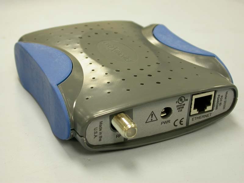
Click to zoom
Application Details
- Equipment Class
- JBP - Part 15 Class B Computing Device Peripheral
- Date of Grant
- May 14, 2003
- Application Purpose
- Original Equipment
- Date of Application
- May 14, 2003
- Equipment Note
- Cable Modem
- Company
- Arris International, Inc.
- Country
- United States
Documents & Files
Document Text
Text extracted from the exhibit documents filed with the FCC. Open a document above to read the original.
Users Manual
Series 7000 SD300 Access Appliance User’s Guide Revision 2 July 2003 60100x-00x Preliminary Warning: This product may not be exported outside the United States and Canada without authorization from the U.S. Department of Commerce, Bureau of Export Administration. Any export or re-export by the purchaser, directly or indirectly, in contravention of U.S. Export Administration Regulation is prohibited. This document may not be reproduced, in whole or part, without the written permission of coaXmedia, Inc. The contents of this document are subject to change without notice. coaXmedia, Inc. assumes no liability for damages resulting from the use of this product or for the information contained in this manual. coaXmedia and the coaXmedia logo are trademarks of coaXmedia, Inc. All trademarked products mentioned in this document are trademarks of their respective companies. © Copyright 2001 coaXmedia, Inc. All rights reserved. Printed in U.S.A. Limited Warranty coaXmedia guarantees that every SD3-Series Access Appliance will be free from physical defects in material and workmanship under normal use for one (1) year from the date of purchase. If the product is determined to be defective during the warranty period, please call coaXmedia’s or your equipment provider’s Customer Support to obtain a Returned Material Authorization (RMA) number. The RMA number should be clearly marked on the outside of the package, when it is shipped. If returned product is determined to be functioning properly, a nominal processing fee may be charged to cover shipping and handling. This product contains no end-user serviceable parts; authorized technicians should perform all service. IN NO EVENT WILL COAXMEDIA BE LIABLE FOR ANY DIRECT, INDIRECT, CONSEQUENTIAL, INCIDENTAL, SPECIAL OR EXEMPLARY DAMAGES ARISING OUT OF THE USE, INABILITY TO USE, OR PERFORMANCE OF THE COAXMEDIA PRODUCT (S), ITS ACCOMPANYING SOFTWARE, OR DOCUMENTATION, INCLUDING WITHOUT LIMITATION DAMAGES FOR LOSS OF BUSINESS PROFITS OR BUSINESS INTERRUPTION, BASED UPON PRINCIPLES OF CONTRACT, WARRANTY, NEGLIGENCE, STRICT LIABILITY OR OTHER TORT, BREACH OF ANY STATUTORY DUTY, PRINCIPLES OF INDEMNITY OR CONTRIBUTION, EVEN IF COAXMEDIA HAS BEEN ADVISED OF THE POSSIBILITY OF SUCH DAMAGES. Furthermore, coaXmedia makes no warranty or representation (expressed, implied, or statutory) with respect to its products, accompanying software, or documentation, or to their use, as well as disclaims against their quality, performance, merchantability, or fitness for any particular purpose. Therein, coaXmedia does not warranty that the products will be error free or will operate without interruption. coaXmedia reserves the right to revise or update its products, software, or documentation without obligation to notify any individual or entity. FCC Compliance The coaXmedia access appliance has been tested and found to comply with the limits for a Class B personal computer and peripherals, pursuant to Part 15 of the FCC Rules. These limits are designed to provide reasonable protection against harmful interference in a residential installation. This equipment generates, uses, and can radiate radio frequency energy, and, if not installed and used in accordance with the instructions, may cause harmful interference to radio communications. However, there is no guarantee that interference will not occur in a particular installation. If this unit does cause harmful interference to radio or television reception, which can be determined by turning the unit off and on, the user is encouraged to try to correct the interference by one of more of the following measures: • Reorient or relocate the receiving antenna • Increase the separation between the equipment and the receiver. • Connect the equipment into an outlet on a circuit different from that to which the receiver is connected • Consult the dealer or experienced radio/TV technician for help. Warning: FCC Regulations state that any unauthorized changes or modifications to this equipment not expressly approved by the manufacturer could void the user's authorization to operate this equipment. Canadian Compliance This Class B digital apparatus complies with Canadian ICES-003. Cet appareil numérique de classe B est conforme à la norme Canadienne NMB- 003. NEC Compliance The SD300 Access Appliance is intended to be connected to a cable system, which has been properly grounded in accordance with the National Electric Code. UL Compliance To insure proper operation and UL compliance of the SD300 Access Appliance in the USA, only use a GlobTek model 48-5-1000R power supply. coaXmedia Series 7000 Table of Contents i Table of Contents Table of Contents ......................................................................... i Contact Information .................................................................... 1 1 Important Rules for Safe Operation...................................... 2 1.1 Service ................................................................................. 3 2 Introduction .......................................................................... 4 2.1 Features ............................................................................... 4 2.2 What You Have ..................................................................... 5 2.3 What You Need ..................................................................... 5 2.3.1 Building Requirements .................................................... 5 2.3.2 Personal Computer Requirements .................................... 5 Using this Guide .............................................................................. 6 3 About the Access Appliance .................................................. 7 3.1 Front Panel ........................................................................... 7 3.2 Rear Panel ............................................................................ 8 4 Installing the Access Appliance ............................................ 9 4…
Text truncated - open the document above for the full version.
Cover Letter(s)
Response to TCB Findings Q: Please describe the measurement detector settings used for conducted emissions test. Has all the testing been performed between 0.15-30MHz for all power supplies? Response: The measurements were taken with quasi-peak detector and compared to average limits. For FCC we only need the 120V supply and it was tested between 0.15-30MHz. Q: The conducted emissions limits are for Class A device in the test report, please supply data compared to Class B limits. Response: Supplied, please see amended pages to the test report. Readings remain the same, but the limits are corrected. Q: The RBW setting for 30MHz to 5GHz is shown as 120kHz on page 11 of the report. Please explain. Response: The RBW setting was 1MHz for frequencies between 1-5GHz and 120kHz for frequencies between 30MHz to 1GHz. This has been clarified in the amended pages to the test report. Please refer to that document.
ID Label/Location Info
.97 6 3.90 3 1.95 1 1 . 1 50 .6 2 5 .74 9 .302 .04 9 .5 4 3 DIA. 0.49 0 DIA . 0.3 4 0 N O TE S: 1. MATERIAL: 0 . 0 1 5 " MATTE P O LY C ARB O NATE FIL M 2. LABEL TO BE ADHESIVE BACKED WITH ACRYLIC PSA3. LABEL BACKGROUND COLOR: PANTONE 429C4. LABEL TEXT COLOR: PROCESS BLACK 408025-001 LABEL, FCC, SD300, MADE IN USA Model SD300 FCC ID: PG4SD300 Made in the U.S.A. RF PWR ETHERNET 408026-001 LABEL, FCC, SD301, MADE IN USA Model SD300 FCC ID: PG4SD301 Made in the U.S.A. RF PWR ETHERNET 408027-001 LABEL, FCC, SD300, MADE IN MEXICO Model SD300 FCC ID: PG4SD300 Made in Mexico RF PWR ETHERNET 408028-001 LABEL, FCC, SD301, MADE IN MEXICO Model SD300 FCC ID: PG4SD301 Made in Mexico RF PWR ETHERNET 4 3 2 1 4 A BC D A BC D 3 2 1 REVI S I O N S Z O N E REV DE SC RIPTI ON D AT E APPR O VE D - A NEW 04 / 13 / 200 3 - S HEE T 1 O F 1 1 :1 SC ALE : A 4080 -001 DWG N O. B D C MFG . ENG : ANGLE S = ± 0.5 ∞ . X = ± 0.03 . XX = ± 0.01 . XXX = ± 0.005 REV DWG S IZ E SC ELE C. ENG : LABEL , FCC , SD300/SD301 , MADE IN U.S.A./MEXIC O BW S ME C H . ENG : T O LERAN C E S BW S D S GN BY : BW S DWG BY : THIRD ANGLE PR OJ E C TI ON D AT E S IGNAT U RE S THE INF O RMATI O N CO NTAINED HEREIN I S CO NFIDENTIAL AND PR O PRIETARY D OCU MENTATI O N BEL O NGING EX C L US IVELY T O CO AXMEDIA AND S HALL N O T BE US ED O R REPRODUCED IN ANY MANNER , OR DISCLOSED T O O THER S WITH OU T PRI O R WRITTEN PERMI SS I O N O F CO AXMEDIA . 1220 OAK INDUSTRIAL LANE , SUITE B . CUMMING , GA 3004 1 ( 678 ) 513-6109 / FAX ( 678 ) 513-611 2 WWW .CO AXMEDIA .COM CO NFIDENTIAL AND PR O PRIETARY INF O RMATI ON 262628 28
Operational Description
Brief product description: The SD-Series Access Appliance is a modem allowing high-speed Internet connectivity over existing in building coaxial distribution networks. It consists of a full duplex QPSK cable transceiver, some control logic circuitry and a digital interface to the user’s computer. Theory of operation: The user’s computer is connected to the Access Appliance through its Ethernet port. After processing by the digital section, the data from the user’s computer is BPSK or QPSK modulated on a 915MHz carrier. The resulting upstream signal is amplified, filtered and then transmitted over the coaxial cable. The upstream symbol rate is 12MS/s. Simultaneously the access appliance receives and demodulates the downstream signal from coaXmedia’s broadband gateway. The 22.5MS/s QPSK downstream signal is centered at 976MHz. The demodulated data is decoded by the Access appliance digital section and sent to the user’s computer via the Ethernet interface.
Test Report
RF Emissions Test Report To Determine Compliance With: EN55022 and FCC, Part 15 Rules and Regulations Model number: SD300 April 22, 2003 Manufacturer: CoaXmedia 1220 Oak Industrial Lane Suite B Cumming, GA 30041 EMC Testing Laboratories, Inc. authorizes the above company to reproduce this report provided it is reproduced in its entirety EMC Testing Lab. (770) 781-9228 Test report no. 03-140A Page 2 2 of 2 2 0 0 Contents Section General Information..................................................... 1 Test Summary............................................................................... 2 Standard Reference ...................................................................... 3 Test Method ....................................................................... 4 Radiated Emissions Measurements ............................................. 5 Conducted Emissions Measurements................................. 6 Configuration and Photographs .................................................. 7 EMC Testing Lab. (770) 781-9228 Test report no. 03-140A Page 3 3 of 2 2 0 0 Section 1 General Information Manufacturer: CoaXmedia 1220 Oak Industrial Lane Suite B Cumming, GA 30041 Manufacturer representative: Mr. Stephane Chapeau Equipment covered by this report: Model number: SD300 Options covered by this report: None Equipment serial no. Prototype Test specifications: To determine compliance with: CISPR 22/EN55022 and FCC, Part 15, Subpart B Rules and Regulations. Class B Test report number: 03-140A Test commenced: April 21, 2003 Test completed: April 21, 2003 Test engineer: Ed Barnes Test Facility: The test facility used to perform these tests is on file with the FCC under registration number 637500 and located at: EMC Testing Laboratories, Inc. 2210 Justin Trail Alpharetta, GA 30004 EMC Testing Lab. (770) 781-9228 Test report no. 03-140A Page 4 4 of 2 2 0 0 Section 2 Test report summary sheet 1 of 3 Summary: Tests Results FCC, Part 15, Class B, Radiated emissions: Pass FCC, Part 15, Class B, Conducted emissions: Pass EN55022, Class B, Radiated emissions Pass EN55022, Class B, Conducted emissions Pass 1- The product(s) covered by this report was found to comply with the Class B limits of the FCC, Part 15, Subpart B Rules and Regulations and CISPR 22/EN55022. 2- The minimum margin of compliance was –11.0 dBμv/m at 49.6 Mhz followed by –21.1 dBμv/m at .45 Mhz. 3- The test results apply only to the products identified on the test report. Product description: The equipment under test (EUT) consisted of a model SD300, broadband gateway for use in enabling high-speed Internet connectivity over a building’s coaxial distribution system. Provided with an external power supply, manufactured by Ventronics, part no. R48W051000-14/1, rated 120V or manufactured by GlobTek, part no. GT-3T48-5- 10000R-3 or WR23A10000LCP-N, rated 220V. During the 120V conducted emissions testing the EUT was powered from an external I.T.E. power supply, manufactured by Ventronics, part no. R48W051000-14/1 During the 220V conducted emissions testing the EUT was powered from an external I.T.E. power supply, manufactured by GlobTek, part no. GT-3T48-5-10000R-3 and WR23A10000LCP-N. The enclosure is constructed of thermoplastic material with overall dimensions measuring 11.5cm wide by 13.5cm deep by 3.0cm maximum height and encloses the following components judged as critical: 1. A printed wiring board manufactured by coaXmedia, part no. 311010-001, Rev. A. EMC Testing Lab. (770) 781-9228 Test report no. 03-140A Page 5 5 of 2 2 0 0 Test report summary sheet 2 of 3 Test configuration: The equipment under test was set-up and configured as specified by the manufacturer as follows: Note: The broadband gateway was positioned away from the EUT during testing. 1- The EUT was connected to the following support peripherals: A) A laptop computer, manufactured by Dell, part no. PPX, serial no. 62HMN, FCC marked. B) A mouse, FCC ID: C3KKMP1. C) A broadband gateway. D) Printer, manufactured by HP, model no. 712C, FCC ID: B94C4557X. 2- The EUT utilized the following cables and were connected as indicated below: A) An unshielded Ethernet cable, part no. 506009-001 was connected from the EUT’s Ethernet port to the laptop computer’s Ethernet port. B) An unshielded, coax cable was connected to the broadband gateway. C) An unshielded power cord, integral to the external power supply, was connected to the EUT’s INPUT power port. D) A standard printer cable connected the printer to the laptop computer. Test operation: For all measurements, the equipment under test was caused to function in a continuous mode of operation for maximum electrical activity as specified by the manufacturer. Specifically, the EUT was made to continuously send and receive a ping signal between the laptop and the broadband gateway. EMC Testing Lab. (770) 781-9228 Test report no. 03-140A Page 6 6 of 2 2 0 0 Test report summary sheet 3 of 3 Marking: (For the European market and Class A products only) Class A products are marked as follows: Warning: This is a Class A product. In a domestic environment, this product may cause radio interference in which case the user may be required to take adequate measures. Modifications: The following modifications were required to comply with the radiated emission limits: 1. When provided with the power supply manufactured by GlobTek, part no. WR23A10000LCP-N, a capacitor, C309, rated 680 μF is required. Engineering Statement: All measurement data of this test report was taken in accordance with the European Normative EN55022 (1994), FCC, Part 15, Subpart B Rules and Regulations and ANSI C63.4-1992 by EMC Testing Laboratories, Inc. located in Alpharetta, Georgia. Although this data is taken under stringent laboratory conditions and, to the best of our knowledge, represents accurate data, it must be recognized that emissions from or immunity to this type equipment may be greatly affected by the final installation of the equipment. Therefore, EMC …
Text truncated - open the document above for the full version.
Test Report
INSTRUMENTATION: Radiated and conducted signal strength measurements were taken with a spectrum analyzer. Radiated emissions were measured with broadband and tuned dipole antennas. Conducted emissions were measured with a 50ohm/50μH line impedance stabilization network (LISN). The test equipment consists of the following: Test Equipment Model No. Serial No. Cal. Due Spectrum Analyzer HP 8591A 3144A02506 01-06-04 Spectrum Analyzer 8592L 3649A00744 01-10-04 LISN 94641-1 0145/0146 06-05-03 LISN 3825/2 9305-2088 08-21-03 LISN LI-210 25145 07-10-03 Biconical Antenna 3110B 1708 10-01-03 Biconical Antenna BIA-25 2451 09-18-03 Log Periodic LPA25 1112 10-01-03 Dipole Antenna DM-105A-T1 31402-110 06-05-03 Dipole Antenna DM-105A-T2 31402-105 06-05-03 Dipole Antenna DM-105A-T3 31402-109 06-05-03 Horn Antenna 3115 9405-4264 10-01-03 R.F. Amplifier QB-820 11602 01-11-04 Preamplifier 8449B 3008A00914 01-07-04 DETECTOR FUNCTION: All measurements were taken using a peak hold signal detector function. In this mode, the spectrum analyzer makes continuous scans across the frequency band and stores the highest emission value detected at each frequency for all scans. The peak hold integration will detect transient or low duty cycle emissions peak which might be missed on single scan measurement. The emission value at each frequency was a true value. SPECTRUM ANALYZER SETTING: For all measurements, the spectrum analyzer was set for a 10 dB input attenuation, 10 dB/Division vertical scale and 90 or 100 dBμV reference level. The resolution bandwidth was set at 9 Khz for the 0.15 - 30 Mhz span, at 120 Khz for 30 Mhz to 1.0 Ghz and 1 Mhz from 1 Ghz to 5.0 Ghz span. The video bandwidth and sweep rate were automatically coupled by the analyzer. EMC Testing Lab. (770) 781-9228 Test report no. 03-140A Page 2 2 of 4 4 RADIATED EMISSIONS MEASUREMENTS Model number: SD300 Test Date: 04/21/03 Frequency Mhz Measurement Reading dBμV/m Corrected Reading dBμV/m EN55022 Limit dBμV/m FCC Limit dBμV/m Minimum Margin dBμV/m Vertical 30.6 22.1 14.2 30.0 29.5 - 15.3 125 28.0 19.4 30.0 33.0 - 10.6 Horizontal 49.6 39.2 28.0 30.0 29.5 - 1.5 200 30.5 22.1 30.0 33.0 - 7.9 400 28.4 24.7 37.0 35.5 - 10.8 700 25.3 28.5 37.0 35.5 - 7.0 EMC Testing Lab. (770) 781-9228 Test report no. 03-140A Page 3 3 of 4 4 CONDUCTED EMISSIONS MEASUREMENTS Model number: SD300 Test voltage: 120V 60Hz Test Date: 04/21/03 Power supply, Ventronics, Part no. R48W051000-14/1 Frequency Mhz Reading dBuV, L1 Frequency Mhz Reading dBuV, L2 FCC Limit, dBuV Margin dBuV .498 29.6 .450 44.9 47.0 -2.1 18.6 21.2 17.7 35.8 50.0 -14.2 - - 18.3 35.3 50.0 -14.7 - - 20.2 31.1 50.0 -18.9 EMC Testing Lab. (770) 781-9228 Test report no. 03-140A Page 4 4 of 4 4 Conducted Emissions Measurements cont... Model number: SD300 Test voltage: 220V 60Hz Test Date: 04/21/03 Power supply, Globtek, part no. GT-3T48-5-1000R-3 Frequency Mhz Reading dBuV, L1 Frequency Mhz Reading dBuV, L2 CISPR Limit, dBuV Margin dBuV .474 38.7 .450 26.3 46.6 -20.3 16.3 36.0 16.3 34.0 50.0 -14.0 21.6 37.6 17.7 33.1 50.0 -12.4 Power supply, Globtek Inc. – Part No. WR23A1000 LCP-N Frequency Mhz Reading dBuV, L1 Frequency Mhz Reading dBuV, L2 CISPR Limit, dBuV Margin dBuV .15 38.8 .15 34.8 56.1 -17.3 .79 24.0 .79 24.4 46.0 -21.6 2.3 20.7 2.3 21.8 46.0 -24.2 14.6 19.1 14.6 21.6 50.0 -28.4
Contact Information
Applicant
Ed Champion
Test Firm
EMC Testing Laboratories, Inc.Gene Bailey
Technical Specifications
| # | Rule Parts | Frequency Range | Power Output |
|---|---|---|---|
| 1 | 15B | - | - |
Other Applications from Arris International, Inc.
PG4SD230
Oct 16, 2003SD230 WLAN Access Modem
Equipment Class
DTS - Digital Transmission System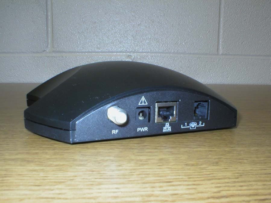
PG4SD220
Aug 14, 2003Cable Modem
Equipment Class
JBP - Part 15 Class B Computing Device Peripheral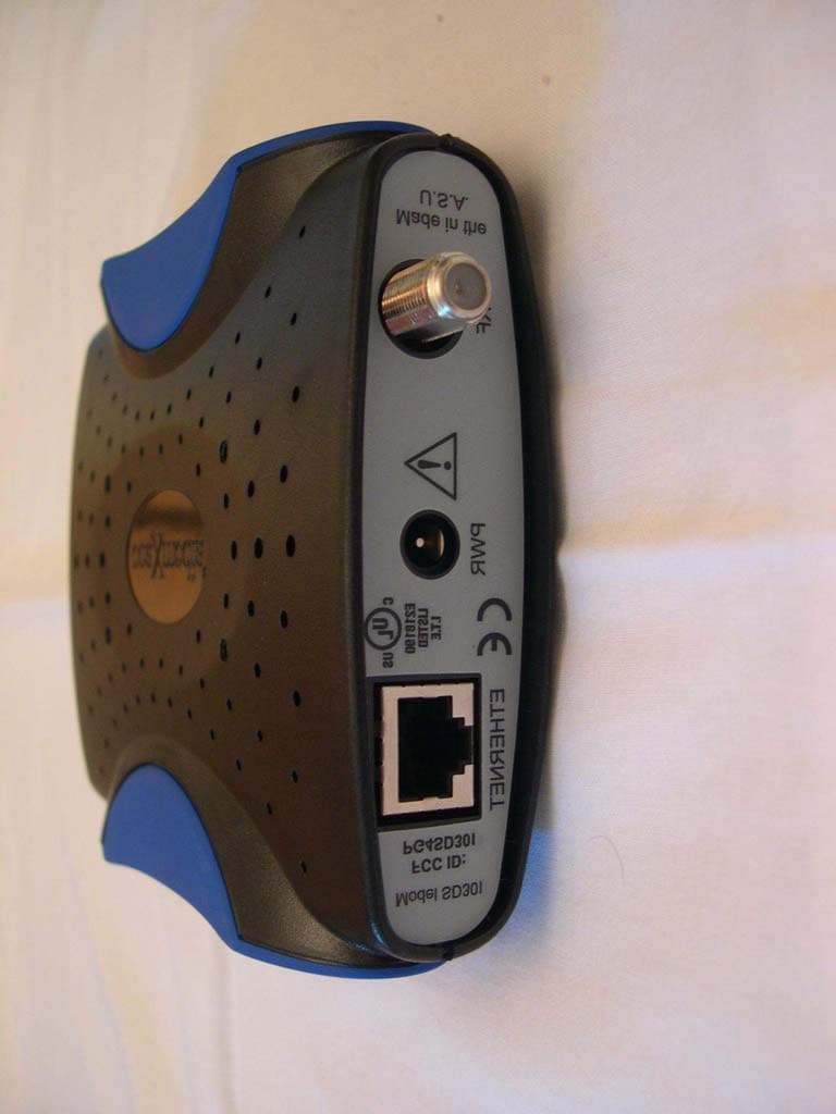
PG4SD301
Jul 10, 2003Cable Modem
Equipment Class
JBP - Part 15 Class B Computing Device Peripheral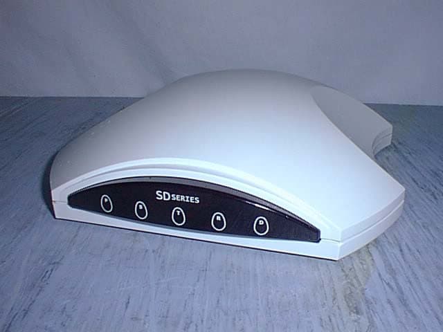
PG4SD201
Apr 18, 2002SD201 Acess Applicance
Equipment Class
JBP - Part 15 Class B Computing Device Peripheral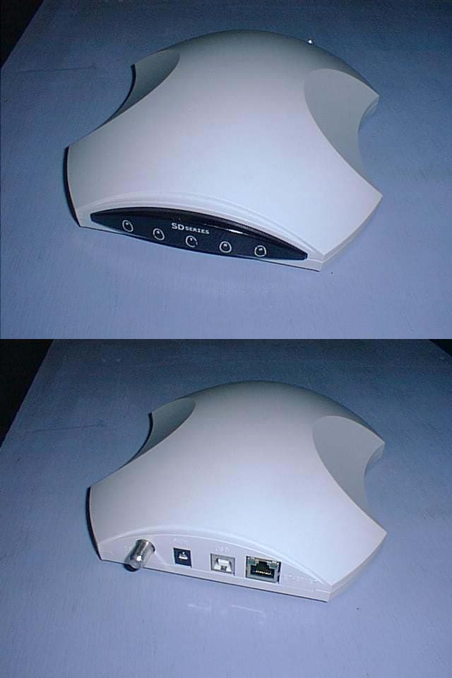
PG4SD20X
Dec 19, 2001SD200 Access Appliance
Equipment Class
JBP - Part 15 Class B Computing Device Peripheral