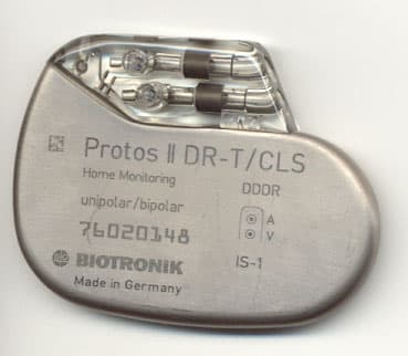
PG6BA0TPhilos DR-T (aka Actros C-T)
Biotronik, Inc.
Click to zoom
Application Details
- Equipment Class
- TNT - Licensed Non-Broadcast Transmitter Worn on Body
- Date of Grant
- Mar 24, 2003
- Application Purpose
- Original Equipment
- Date of Application
- Feb 12, 2001
- Equipment Note
- Philos DR-T (aka Actros C-T)
- Frequency Range
- 403.60000000 - 403.60000000
- Company
- Biotronik, Inc.
- Country
- United States
Documents & Files
Document Text
Text extracted from the exhibit documents filed with the FCC. Open a document above to read the original.
Users Manual
EXHIBIT O – User Manual FCC ID# PG6BA0T Using the BA03 DDDR Pacemaker 1 Using the BA03 DDDR Pacemaker CAUTION: FEDERAL (USA) LAW RESTRICTS THIS DEVICE TO SALE BY OR ON THE ORDER OF, A PHY- SICIAN (OR PROPERLY LICENSED PRACTITIONER). Software SWM 1000/B-KT0.0 This software must only be used for follow-ups involv- ing BA03 DDDR pacemakers. The BA03 DDDR and Actros DR pacemakers are han- dled almost the same way. ä Please consult the Actros DR + or the SWM 1000/B- K00.0 manual for a description of Actros DR features In addition to the description in the SWM 1000/B-K00.0 manual, the following special features are included in the B-KT0.0 software: •The list of pacemakers contains only the BA03 DDDR Home Monitoring device. •The Home Monitoring functions and parameters are only available with the B-KT0.0 software. •All statistical functions can be used simultaneously. No preselection is necessary. •Both the rate trend and the sensor trend can be dis- played. •The trend for the gain monitor is not available. This software can be ordered by using the following Catalog No.: SWM 1000/B-KT0.0.A332 076 Note:This software can only be used with the BIOTRONIK programmers EPR 1000 Plus and TMS 1000 Plus . Home Monitoring - Introduction 2 Home Monitoring - Introduction The pacemaker BA03 DDDR is the newest member of the Actros + family, that consists of pacemakers for treatment of bradycardia arrhythmia. The pacemaker is identical to the Actros DR + in that it is a rate adaptive, dual chamber system with separate atrial and ventric- ular leads and is suited for patients who need AV syn- chronous pacing. BA03 DDDR has the functionality of a current DDDR pacemaker and is additionally equipped with the Home Monitoring function Home Monitoring This function is part of a complete Home Monitoring system, in which information about the cardiac condi- tion of the patient can be transmitted using wireless technology between implant, patient and physician. The Home Monitoring function is used to obtain mes- sages from the implant and to compile these mes- sages into tables and graphs. Thus, the course of the therapy can be optimzied by setting up an additional follow-up between regularly scheduled visits, if neces- sary. The implants’ Home Monitoring function can be used during the entire service time of the implant or in shorter periods, e.g., a few weeks or months. Transmission of message For the transmission of the message, the implant is equipped with a small transmitter that has a range of approx. 2 m. The patients’ implant data is transmitted to the respective patient device in certain, adjustable periods. The minimum distance between implant and patient device is 15 cm. The patient can activate the transmission himself by application and immediate removal of a magnet over the implant . Patient device with components The patient device (Fig.1) is developed for home use and consists of a mobile unit and the respective charg- ing station. The patient can also carry the mobile unit with them in their normal daily activities. The patient device rechargeable batteries that make an operating time of about 24 h possible. The patient device receives messages from the implant and for- 3 Home Monitoring - Introduction wards them to a BIOTRONIK Ser- vice Center via mobile communi- cations. Fig.1 Patient Device with Charging Station RUC 200 Cardio Report The service center compiles the messages into a com- prehensive report (Cardio Report). This Cardio Report is tailored to the individual needs of the patient and is sent to the attending physician via fax. •For further information about the patient device, please refer to the respective Users Manual. •The standard functions are described in the Actros + family techncial manua . •The additional Home Monitoring functions of the BA03 DDDR are found in this manual Indications and Contraindications 4 Indications and Contraindications For the general indications and contraindications please refer to the Actros + Family technical manual. Basically, the indications and contraindications of the BA03 DDDR are identical to that for the rate adaptive dual chamber pacemaker Actros DR + . The special cri- teria for the Home Monitoring Function are described as follows: Criteria for using Home Monitoring There are no contraindications for use of the Home Monitoring function. This function has no influence on the diagnostic or therapeutic functionality of the pace- maker. The patient must be capable and willing to manage certain tasks associated with Home Monitor- ing. Usage of the Home Monitoring system is inappro- priate in the following cases: •The patient can not handle the system as intended, because of their physical or psychological condition. •There is no GSM cellular service available in the local area of the patient’s home. •The patient often stays (i.e. works) in areas where it is not permitted to use mobile phones. Note:Home Monitoring does not replace the regular fol- low-up examination. When using the Home Monitoring function, the time interval between the follow-ups must not be pro- longed. Caution: The data transmitted by Home Monitoring are not suitable for diagnosis, because not all information available in the implant is being transmitted. 5 Transmission of Message Transmission of Message The Home Monitoring function can be switched ON or OFF with the programming device. If the Home Moni- toring function is active, the transmission of the implant data can be triggered as follows: •Periodic message at predefined time intervals •Message activated by the patient The attending physician himself decides if the patient should trigger a transmission by programming this paramater ON or OFF. The patient activated message does not effect the programmed periodic message. Note:Please note that with the BA03 DDDR, the Home Mon- itoring function is only possible in following pacing modes: DDD, DDDR, DDI, DDIR. Periodic Message The time and interval (Monitoring Interval) of the peri…
Text truncated - open the document above for the full version.
Cover Letter(s)
EXHIBIT A – Agent Authorization Letter FCC ID# PG6BA0T
Cover Letter(s)
EXHIBIT C – Cover Letter from Agent FCC ID# PG6BA0T NORTHWEST EMC, INC. 22975 NW Evergreen Parkway, Suite 400 Hillsboro, OR 97124 Dear Application Examiner: On behalf of Biotronik, Inc., Northwest EMC, Inc is submitting this application for the certification of Biotronik’s Medical Implant Transmitter, Model Philos DR-T (a.k.a. Actros C-T). The transmitter is seeking authorization under the Medical Implant Communications Service (MICS, Part 95.603) as an ultra-low power transmitter. The transmitter is integral to a medical pacemaker and facilitates non-voice data communications with physicians. The pacemaker with the transmitter is a stand-alone device. It has an internal power source (lithium iodine battery) The transmitter operates at 403.6 MHz, using FSK modulation with an occupied bandwidth of 46 kHz The technical report and exhibits demonstrate compliance with FCC rules 47 CFR 95.603. To facilitate the review process, an index of exhibits has been provided (see file “Index of exhibits.pdf”). Your efforts in reviewing this application are greatly appreciated. Best regards, Greg Kiemel, Director of Engineering Northwest EMC, Inc.
Cover Letter(s)
EXHIBIT J – Request for Confidentiality FCC ID# PG6BA0T
Cover Letter(s)
Exhibits for the FCC application of Biotronik, Inc. Philos DR-T (aka Actros C-T) FCC ID: PG6BA0T Exhibit Description File Name Confidential Exhibit A Agent Authorization Letter Agent Authorization Letter.pdf Exhibit B Antenna Description Antenna Description.pdf Yes Exhibit C Cover Letter from Agent Cover Letter from Agent.pdf Exhibit D FCC ID Label FCC ID Label.pdf Exhibit E Frequency Block Diagram Frequency Block Diagram.pdf Yes Exhibit F Modulation Description Modulation Description.pdf Yes Exhibit G Operational Description Operational Description.pdf Yes Exhibit H Internal Photos Internal Photos.pdf Yes Exhibit I External Photos External Photos.pdf Exhibit J Request for Confidentiality Request for Confidentiality.pdf Exhibit K Schematics Schematics.pdf Yes Exhibit L Test Setup Photos Test Setup Photos.pdf Exhibit M Acceptance Test Procedure Acceptance Test Procedure.pdf Yes Exhibit N Acceptance Test Specification Acceptance Test Specification.pdf Yes Exhibit O User Manual User Manual.pdf Exhibit P Frequency Stability Data Frequency Stability.pdf Exhibit Q Radiated Emissions Data Radiated Emissions.pdf Exhibit R Occupied Bandwidth Data Occupied Bandwidth.pdf Exhibit S SAR Analysis SAR Analysis.doc Exhibit T Technical Report Technical Report.pdf
External Photos
EXHIBIT I – External Photos FCC ID# PG6BA0T
ID Label/Location Info
EXHIBIT D – FCC ID Label FCC ID# PG6BA0T FCC ID Labeling Scheme Per 47 CFR 2.926 (e), “Where it is shown that a permanently affixed nameplate is not desirable or is not feasible, an alternative method of positively identifying the equipment may be used if approved by the Commission. The proposed alternative method of identification and the justification for its use must be included with the application for equipment authorization. Note: As an example, a device intended to be implanted within the body of a test animal or person would probably require an alternate method of identification.” Since the EUT is implanted in the human body, the FCC ID will not be applied to outside of the device. Instead, the applicant is proposing the following alternate method of applying the FCC ID number to two locations: 1. The FCC ID, along with the disclosure statement required by 95.1215(a), is in the User Manual (page 19 – see excerpt below). 2. The FCC ID also appears on the package label (see below), which is affixed to outside of the shipping box for the EUT. Packaging Label BA03 DDDR DUAL CHAMBER, Order No.: 122 126 RATE ADAPTIVE PACEMAKER Serial No.: * IS-1, UNI/BIPOLAR Use Before: * ISO 5841-3:1992(E) Rate: 60 ppm DDDR Uncoated Pulse: (A) 3.6 V; 0.4 ms (V) 3.6 V; 0.4 ms NOTE: This unit is designed for use with two (2) Unipolar or Bipolar IS-1 leads meeting the International Standard ISO 5841-3:1992(E). Mode DDD* Lower Rate 60 ppm Home Monitoring OFF Hysteresis OFF Upper Tracking Rate 160 ppm UTR Response 2:1 Dynamic AV Delay MEDIUM ARP Extension 0 ms Safety AV Delay 100 ms Ventricular Blanking Period 24 ms Automatic Mode Conversion OFF Magnet Rate Async Pulse Amplitude (A) 3.6 V; (V) 3.6 V Pulse Width (A) 0.4 ms; (V) 0.4 ms Sensitivity (A) 1.5 mV; (V) 2.5 mV Refractory Period (A) 425 ms; (V) 250 ms Polarity Sense Unipolar Polarity Pace Unipolar *See enclosed Technical Manual for programmable values. CAUTION: Because of the numerous available 3.2 mm configurations, e.g., the IS-1 and the VS-1 standards, lead/pulse generator compatibility should be confirmed with the pulse generator and/or lead manufacturer prior to the implantation of a pacing system. STERILE: Pacemaker as identified and accessories NON-STERILE: Package Inserts STERILIZATION: This unit has been gas sterilized with ethylene oxide. Sterility cannot be guaranteed if the package has been damaged during transportation. Please examine the package carefully before opening. If it shows any evidence of damage or mishandling, it should be returned immediately to BIOTRONIK. Once the box seal has been broken, title passes to the hospital and a purchase order is required. CAUTION: Recommended Storage Temperature: 5° C - 55° C (41° F - 131° F). Federal (U.S.A.) law restricts this device to sale by, or on the order of, a physician. FCC Statement: (FCC ID PG6BA0T) This pacemaker is equipped with an RF transmitter for wireless communications. This device must not interfere with stations operating in the 400.150 - 406.000 MHz band in the Meteorological Satellite or Earth Exploration Satellite Services and must accept any interference received, including interference that may cause undesired operation. Made in Germany B1112-A 02/01 Device / No.: BA03 DDDR / 122 126 Serial No.: * Manufacturer Name/No.:BIOTRONIK / 004 Device / No.: BA03 DDDR / 122 126 Serial No.: * Manufacturer Name/No.:BIOTRONIK / 004 Device / No.: BA03 DDDR / 122 126 Serial No.: * Manufacturer Name/No.:BIOTRONIK / 004 Device / No.: BA03 DDDR / 122 126 Serial No.: * Manufacturer Name/No.:BIOTRONIK / 004 Device / No.: BA03 DDDR / 122 126 Serial No.: * Manufacturer Name/No.:BIOTRONIK / 004 Device / No.: BA03 DDDR / 122 126 Serial No.: * Manufacturer Name/No.:BIOTRONIK / 004 Device / No.: BA03 DDDR / 122 126 Serial No.: * Manufacturer Name/No.:BIOTRONIK / 004 Device / No.: BA03 DDDR / 122 126 Serial No.: * Manufacturer Name/No.:BIOTRONIK / 004 Device / No.: BA03 DDDR / 122 126 Serial No.: * Manufacturer Name/No.:BIOTRONIK / 004 Device / No.: BA03 DDDR / 122 126 Serial No.: * Manufacturer Name/No.:BIOTRONIK / 004 Technical Data 19 Order Information Model Lead ConnectionOrder Number BA03 DDDR uncoated IS-1122 126 Federal Communications Commission Disclosure The BA03 DDDR pacemaker is equipped with an RF transmitter for wireless communications. This transmitter is authorized by rule under the Medical Implant Communications Service (47 CFR Part 95) and must not cause harmful interference to stations operating in the 400.150 - 406.000 MHz band in the Meteorological Aids (i.e., trans- mitters and receivers used to communicate weather data), the Meteoro- logical Satellite, or the Earth Exploration Satellite Services and must accept interference that may be caused by such aids, including interfer- ence that may cause undesired operation. This transmitter shall be used only in accordance with the FCC Rules governing the Medical Implant Communications Service. Analog and digital voice communi- cations are prohibited. Although this transmitter has been approved by the Federal Communications Commission, there is no guarantee that it will not receive interference or that any particular transmission from this transmitter will be free from interference. The FCC ID number for this device is: PG6BA0T.
Internal Photos
EXHIBIT H – Internal Photos FCC ID# PG6BA0T Philos DR-T Pacemaker RF Circuit Outlined in Red (component reference designators match schematic) Philos DR-T Pacemaker electronics with RF circuitry SAW component sets Colpitts oscillator frequency at 403.55MHz Folded Pacemaker Circuit with flex arms for attachment to battery and feedthrough Orange coil is part of magnetically coupled communications system (not part of RF circuit). Backside of Electronics Circuit Board
RF Exposure Info
EXHIBIT S – SAR Analysis FCC ID# PG6BA0T Micro System Engineering, Inc. Confidential SAR Analysis February 3, 2001 2 Specific Absorption Rate (SAR) Analysis Using Finite Difference Time Domain Computation for RF Transmitter Circuit Employed in Biotronik Pacemakers Actros TO+ and Philos DR-T Ed Wardzala Mark Johnson February 3, 2001 Micro System Engineering, Inc. Confidential SAR Analysis February 3, 2001 3 Introduction Biotronik has developed an RF communications system for use in implantable pacemakers allowing for patient data regarding cardiac condition to be transmitted wirelessly to the physician for evaluation. The amount of irradiated power transmitted through the human body using this technology can be defined by a measure termed the Specific Absorption Rate (SAR). Values of SAR that can be safely used in these applications have been defined by ANSI/IEEE and are part of the FCC guidelines for medical implant communications. Certification of medical-implant transmitters under the FCC Part 95 Medical Implant Communication Service (MICS) requires a measurement or Finite Difference Time Domain (FDTD) analysis of the SAR associated with the presence of a non-ionizing, radio frequency (RF) transmitter. This report details the SAR analysis of the unidirectional RF transmitter found in Biotronik’s Philos DR-T and Actros TO+ pacemakers. Summary Using a commercially available FDTD program (XFDTD, Remcom Inc.), the computed SAR values determined by this analysis are: Maximum SAR 4.54 mW/kg Maximum 1g average SAR1.11 mW/kg Average SAR427 nW/kg The ANSI C95-1-1992 limit is 1.6 W/kg. The computed value in this study of the maximum SAR is 4.54 mW/kg. The margin between the maximum attained SAR and the ANSI/IEEE specification limit is 25.5 dB (only 0.28% of the specification limit). These FDTD results prove that the Biotronik RF transmitter circuitry can safely be used in its intended application with respect to the energy emitted during communication. Method of Analysis Equipment and tools used for the analysis: Hardware Dell dual processor Windows 2000 Workstation, 1 Gb RAM 3 drive SCSI RAID Hewlett-Packard 8591 Spectrum Analyzer Hewlett Packard 8753E Vector Network Analyzer Software XFDTD 5.1.0.5 Bio-Pro, Calc FDTD 5.1, Remesher 5.1, HIFI Body model Eagleware SuperStar Pro. 6.5b MicroSim PSPICE ver 8.0 Micro System Engineering, Inc. Confidential SAR Analysis February 3, 2001 4 The computational tool used for this FDTD analysis was XFDTD with the hi-fidelity Visible Man model (also from Remcom). The first proposed method for analysis was to use the subgrid tool where the implant at 1 mm 3 resolution would be placed in the biomodel, which is meshed at 5mm 3 . It was found that the subgrid technique, when used with high-dielectric constant materials, does not yield a stable solution. This was verified with Remcom 1 . Because it was desirable to show the fine structure of the implant, and yet restrict the computational effort of the equipment, a mesh size of 2 mm 3 was chosen for the analysis. Note: This 2mm mesh provides for resolution 15 times greater than the 5mm grid pattern that has been used by Biotronik competitors in similar applications for their analysis to prove compliance with the SAR limit safety standards. The biomesh was resampled to a 2mm 3 grid, and the body was truncated to include only the torso (Figure 1). Limiting analysis to the torso was deemed rational as the RF power emanates from the pacemaker located in the chest and remains concentrated within this region as proven in this analysis. While feasible, utilizing the entire human body model complicates the analysis, without providing additional insight into the irradiation properties of the pacemaker signal propagating through the tissue of concern. Figure 1. Truncated Biomesh Resampled at 2mm 3 Micro System Engineering, Inc. Confidential SAR Analysis February 3, 2001 5 Pacemaker Model Remcom, to date, does not have a 3-D import tool and the model of the implant was restricted to the primit ive geometry tools that are currently available. Figure 2 below shows the pacemaker model utilized for this analysis, which is a rectangle-box tool. The loop antenna and pacing lead wires were realized with a combination of PEC wire and thin- wire models. Thin wire models allow any FDTD algorithm to include the effects of wire diameter. The epoxy-header material, shown in light blue, used to enclose the loop antenna, was characterized for values of dielectric constant and conductivity. Using a HP8753E network analyzer and a TEM transmission line test cell, it was found the epoxy has a dielectric constant 0 ~3 and a conductivity ~.001 S/m. The green area is the titanium case. The actual thickness of the titanium case is not 4 mm as shown below; it is on the order of 1/3 mm, but FDTD modeling requires at least 1 full cell width on the wall of a hollow object to correctly model the object. The skin depth of titanium at this frequency is such that the attenuation of an EM wave is not changed with this modeled wall thickness compared to the actual case. The violet and white lines show the loop antenna and the pacing wires, respectively. The upper right corner (violet) shows an area of muscle tissue. This addition of biological tissue was included with the pacemaker to ensure that the pacemaker could be correctly merged with the biological model of Figure 1. As the mesh is 2 mm 3 , Figure 2 shows that the pacemaker is 4.6 cm x 5.0 cm x 1.6 cm. Shown inside the case is a pair of violet, “L” shaped antenna wires for the source. The source cell is thus shielded by the case, as it is in the actual pacemaker, and does not effect the field distribution in the SAR calculation. A photo of the actual pacemaker is shown on the cover of this report. In this photo, the loop antenna is easily identifiable embedded in the header of the device (around the perimeter). Figure 2. Implant Mesh 2 mm 3 Micro System Engineering, Inc. Confidential SAR Analysis Febru…
Text truncated - open the document above for the full version.
Test Report
EXHIBIT P – Frequency Stability Data FCC ID# PG6BA0T Rev 3.2 10/06/99 Comments: Frequency Stability with Variation of Ambient Temperature 403.610094 403.612673 403.613002 Measured Frequency (MHz) 403.611731 403.607063 Assigned Frequency (MHz) 403.6178 403.6178 403.6178 403.6178 403.6178 100 100 100 Specification (ppm) 100 100 26.60 11.89 Tolerance (ppm) Temp ( o C) 25 3012.70 15.04 19.09 35 40 45 Northwest EMC, Inc., Frequency Stability Data Sheets EUT:Serial Number:Job Number:Date: Philos DR-TPROTO1MICROOO112/21/99 Manufacturer:Test Engineer:Job Site: Micro Systems EngineeringGreg KiemelEV Temperature Chamber Customer Reference Number:Software:Power: Battery Transmitting mid band. Temperature (°C):Relative Humidity: See table belowHeld constant at 40%
Test Report
EXHIBIT Q – Radiated Emissions Data FCC ID# PG6BA0T Rev 3.4 10/11/00 Comments: Frequency Meter ReadingDetector Antenna Factor Antenna Polarity Preamp GainCable Loss Table Azimuth Antenna Height Adjusted Level Spec. LimitMarginComment (MHz)(dBuV)(dB/m)(dB)(dB)(degrees)(meters)(dBuV/m)(dBuV/m)(dB) 403.57256.2PK16.1HBLG31.31.149.01.342.185.2-43.1transmit frequency 403.57448.4PK16.1VBLG31.31.157.01.134.385.2-50.9transmit frequency 807.15734.4PK22.1HBLG32.71.689.01.025.446.0-20.7 807.16131.3PK22.1VBLG32.71.64.01.322.346.0-23.7 1210.73739.7PK23.8HHRN35.22.20.01.530.554.0-23.6No detectable signal 1210.73727.2AV23.8VHRN35.22.248.01.318.054.0-36.1No detectable signal 1210.73740.3PK23.8VHRN35.22.248.01.331.154.0-23.0No detectable signal 1210.73727.2AV23.8HHRN35.22.20.01.518.054.0-36.0No detectable signal 1614.31639.7PK25.2HHRN34.62.253.01.532.554.0-21.6No detectable signal 1614.31628.6PK25.2VHRN34.62.20.01.421.454.0-32.7No detectable signal 1614.31626.9AV25.2HHRN34.62.253.01.519.754.0-34.4No detectable signal 1614.31626.9AV25.2VHRN34.62.20.01.219.754.0-34.4No detectable signal 2017.89539.2PK26.9HHRN31.12.50.01.037.554.0-16.5No detectable signal 2017.89539.1PK26.9VHRN31.12.50.01.537.454.0-16.6No detectable signal 2017.89526.8AV26.9HHRN31.12.50.01.025.154.0-29.0No detectable signal 2017.89526.8AV26.9VHRN31.12.50.01.525.154.0-28.9No detectable signal 10/19/00 Rod Peloquin 2241 EUT in test fixture at 1.5m above ground plane, EUT in horizontal polarity 75103203-210 Micro Systems Engineering, Inc MICR0001 Temperature (°C):% Humidity: Customer Reference Number:Software:Power: FCC 95.635 Radiated Specification Limit (3 meter) Northwest EMC, Inc., Radiated and Conducted Emissions Data Sheets EUT:Serial Number:Job Number:Date: Manufacturer:Test Engineer:Job Site: EV01 0.0 10.0 20.0 30.0 40.0 50.0 60.0 70.0 80.0 10100100010000 Frequency (MHz) dBuV/meter THIS DATA WAS ACQUIRED AT AN FCC LISTED FACILITY THE FACILITY MEETS ANSI C63.4 SITE ATTENUATION REQUIREMENTS. THIS FINAL DATA REPRESENTS MAXIMIZED (CABLES, ANTENNA & TURNTABLE) MEASUREMENTS. Rev 3.4 10/11/00 Comments: Frequency Meter ReadingDetector Antenna Factor Antenna Polarity Preamp GainCable Loss Table Azimuth Antenna Height Adjusted Level Spec. LimitMarginComment (MHz)(dBuV)(dB/m)(dB)(dB)(degrees)(meters)(dBuV/m)(dBuV/m)(dB) 403.57250.1PK16.1VBLG31.31.1287.01.936.085.2-49.2transmit frequency 403.57756.2PK16.1HBLG31.31.18.01.342.185.2-43.1transmit frequency 807.14938.5PK22.1VBLG32.71.62.01.429.546.0-16.5 807.16240.9PK22.1HBLG32.71.6352.01.531.946.0-14.2 1210.73742.3PK23.8VHRN35.22.218.01.333.154.0-20.9 1210.73729.0AV23.8VHRN35.22.218.01.319.854.0-34.2 1210.73740.4PK23.8HHRN35.22.215.01.431.254.0-22.9 1210.73727.8AV23.8HHRN35.22.215.01.418.654.0-35.5 1614.31639.8PK25.2VHRN34.62.230.01.232.654.0-21.4 1614.31627.5AV25.2VHRN34.62.230.01.220.354.0-33.7 1614.31639.9PK25.2HHRN34.62.21.01.032.754.0-21.3No detectable signal 1614.31626.8AV25.2HHRN34.62.21.01.019.654.0-34.5No detectable signal 2017.89540.3PK26.9VHRN31.12.50.01.538.654.0-15.5No detectable signal 2017.89526.8AV26.9VHRN31.12.50.01.525.154.0-29.0No detectable signal 2017.89539.4PK26.9HHRN31.12.50.01.537.754.0-16.3No detectable signal 2017.89526.8AV26.9HHRN31.12.50.01.525.154.0-29.0No detectable signal 10/19/00 Rod Peloquin 2241 EUT in test fixture at 1.5m above ground plane, EUT in vertical polarity 75103203-210 Micro Systems Engineering, Inc MICR0001 Temperature (°C):% Humidity: Customer Reference Number:Software:Power: FCC 95.635 Radiated Specification Limit (3 meter) Northwest EMC, Inc., Radiated and Conducted Emissions Data Sheets EUT:Serial Number:Job Number:Date: Manufacturer:Test Engineer:Job Site: EV01 0.0 10.0 20.0 30.0 40.0 50.0 60.0 70.0 80.0 10100100010000 Frequency (MHz) dBuV/meter THIS DATA WAS ACQUIRED AT AN FCC LISTED FACILITY THE FACILITY MEETS ANSI C63.4 SITE ATTENUATION REQUIREMENTS. THIS FINAL DATA REPRESENTS MAXIMIZED (CABLES, ANTENNA & TURNTABLE) MEASUREMENTS. Rev 3.4 10/11/00 Comments: Frequency Antenna Polarity Adjusted LevelMargin (MHz)(dBuV/meter)(dB) 959.898Hor.25.7-20.3 938.954Hor.25.6-20.4 954.573Hor.25.6-20.4 921.205Ver.25.4-20.6 912.685Hor.25.4-20.6 927.950Ver.25.4-20.6 952.443Ver.25.3-20.7 948.184Hor.25.2-20.8 940.374Ver.25.2-20.8 907.716Ver.25.2-20.8 901.326Hor.25.1-20.9 941.084Hor.25.0-21.0 956.703Hor.25.0-21.0 957.413Ver.25.0-21.0 950.669Ver.25.0-21.0 862.278Hor.24.9-21.1 947.119Ver.24.9-21.1 944.634Hor.24.8-21.2 933.984Ver.24.8-21.2 887.837Ver.24.8-21.2 10/19/00 Rod Peloquin 2241 EUT in test fixture at 1.5m above ground plane, EUT in horizontal polarity Philos DR-T75103203-210 Micro Systems Engineering, Inc MICR0001 Temperature (°C):% Humidity: Run #01 Customer Reference Number:Software:Power: FCC 95.635 Radiated Specification Limit (3 meter) Northwest EMC, Inc., Radiated and Conducted Emissions Data Sheets EUT:Serial Number:Job Number:Date: Manufacturer:Test Engineer:Job Site: EV01 31.4-6.646.0 32.2-7.446.0 31.2-6.346.0 31.2-6.446.0 31.3-6.346.0 32.8-7.946.0 31.2-6.246.0 31.2-6.246.0 32.2-7.146.0 31.6-6.646.0 31.8-6.646.0 32.1-6.946.0 31.6-6.346.0 31.5-6.346.0 32.3-6.946.0 32.1-6.746.0 31.9-6.346.0 32.2-6.846.0 31.9-6.246.0 32.2-6.646.0 Meter ReadingCorrection FactorSpecification Limit (dBuV)(dB/m)(dBuV/meter) 0.0 10.0 20.0 30.0 40.0 50.0 60.0 70.0 80.0 101001000 Frequency (MHz) dBuV/meter Rev 3.4 10/11/00 Comments: Frequency Antenna Polarity Adjusted LevelMargin (MHz)(dBuV/meter)(dB) 4980.500Ver.31.7-22.3 4984.500Ver.31.6-22.4 4978.000Ver.31.6-22.4 4986.500Ver.31.6-22.4 4987.500Ver.31.6-22.4 4952.500Ver.31.4-22.6 4949.500Ver.31.4-22.6 4999.500Ver.31.4-22.6 4925.000Ver.31.3-22.7 4951.500Ver.31.3-22.7 4929.000Ver.31.3-22.7 4996.000Hor.31.3-22.7 4850.500Ver.31.3-22.7 4710.000Ver.31.3-22.7 4992.500Ver.31.3-22.7 4906.000Ver.31.2-22.8 4903.000Hor.31.2-22.8 4920.000Ver.31.2-22.8 10/19/00 Rod Peloquin 2241 EUT in test fixture at 1.5m above ground plane, EUT in horizontal polarity Philos DR-T75103203-210 Micro Systems Engineering, Inc MICR0001 Temperature (°C):% Humidity: …
Text truncated - open the document above for the full version.
Test Report
EXHIBIT R – Occupied Bandwidth Data FCC ID# PG6BA0T
Test Report
EXHIBIT T – Technical Report FCC ID: PG6BA0T Measurement/Technical Report Biotronik, Inc., PG6BA0T FCC ID: PG6BA0T October 20, 2000 This report concerns (check one): Original Grant _x_ Class II Change_____ Equipment Type: MICS, Medical Implant Transmitter Rule Part: 47 CFR 95.603 Deferred grant requested per 47 CFR 0.457 (d)(1)(ii)? yes_____ no__X__ If yes, defer until: ______N/A______ date Biotronik, Inc. agrees to notify the Commission by: ______N/A______ date of the intended date of announcement of the product so that the grant can be issued on that date. Report prepared by: Northwest EMC, Inc. 22975 NW Evergreen Parkway, Suite 400 Hillsboro, OR 97124 (503) 844-4066 fax: (503) 844-3826 Report No. MICR0001 FCC ID: PG6BA0T Northwest EMC, Inc. Report No. MICR0001 Page - 2 Table of Contents Section Description Page 1.0 General Information 3 1.1 Product Description 3 1.2 Related Submittals/Grants 4 1.3 Tested System Details 5 Figure 1 Configuration of Tested System 5 1.4 Test Methodology 6 1.5 Test Facility 6 2.0 Technical Description 7 2.1 Type of Emission 7 2.2 Frequency Range 7 2.3 Operating Power Level 7 2.4 DC Voltage and Current Applied 7 2.5 Schematics and Parts List 7 2.6 Block Diagram 7 2.7 Circuit Description 7 2.8 Tune Up Procedure 8 2.9 Description of Modulation System 8 2.10 FCC ID and Disclosure Policies 8 2.11 Modulation Characteristics 8 2.12 Necessary Bandwidth 9 3.0 Occupied Bandwidth 10 4.0 Radiated Emissions 11 5.0 Frequency Stability 13 6.0 RF Exposure Compliance 14 7.0 Measurement Equipment 15 FCC ID: PG6BA0T Northwest EMC, Inc. Report No. MICR0001 Page - 3 1.0 General Information 1.1 Product Description Manufactured By...................................................................................................Biotronik, Inc. Address..................................................6024 SW Jean Rd. Building B, Lake Oswego, OR 97035 Test Requested By:..............................................................................................Mark Johnson Model..........................................................................................Philos DR-T (a.k.a. Actros C-T) FCC ID......................................................................................................................PG6BA0T Applicable FCC Rule Part(s).......................................................................MICS, 47 CFR 95.603 Serial Number(s)..................................................................................................75103203-210 Date of Test..............................................................................................October 19 - 20, 2000 Job Number...............................................................................................................MICR0001 Prepared By: Vicki Albertson, Technical Report and Documentation Manager Technical Review B…
Text truncated - open the document above for the full version.
Contact Information
Applicant
Mark Johnson(New Business Development Manager)
Technical Contact
Northwest EMC, IncGreg V Kiemel
[email protected]503-844-4066
22975 NW Evergreen Parkway · Hillsboro, Oregon · United States
Non-Technical Contact
Northwest EMC, Inc.Vicki L Albertson
[email protected]503-844-4066
Test Firm
Northwest EMC, Inc.Greg Kiemel
Technical Specifications
| # | Rule Parts | Frequency Range | Power Output | Emission | Tolerance |
|---|---|---|---|---|---|
| 1 | 95 | 403.6 MHz - 403.6 MHz | 0.00 µW | 46K0F1D | 26.6000000000 ppm |
Other Applications from Biotronik, Inc.
PG6CYLOS
Nov 21, 2005Cylos DR-T
Equipment Class
TNT - Licensed Non-Broadcast Transmitter Worn on Body
PG6BELOS-T
May 06, 2004Belos DR-T, Belos VR-T, and Cardiac Airbag-T
Equipment Class
TNT - Licensed Non-Broadcast Transmitter Worn on Body
PG6LEXOS-T
Dec 21, 2003Lexos DR-T & Lexos VR-T
Equipment Class
TNT - Licensed Non-Broadcast Transmitter Worn on Body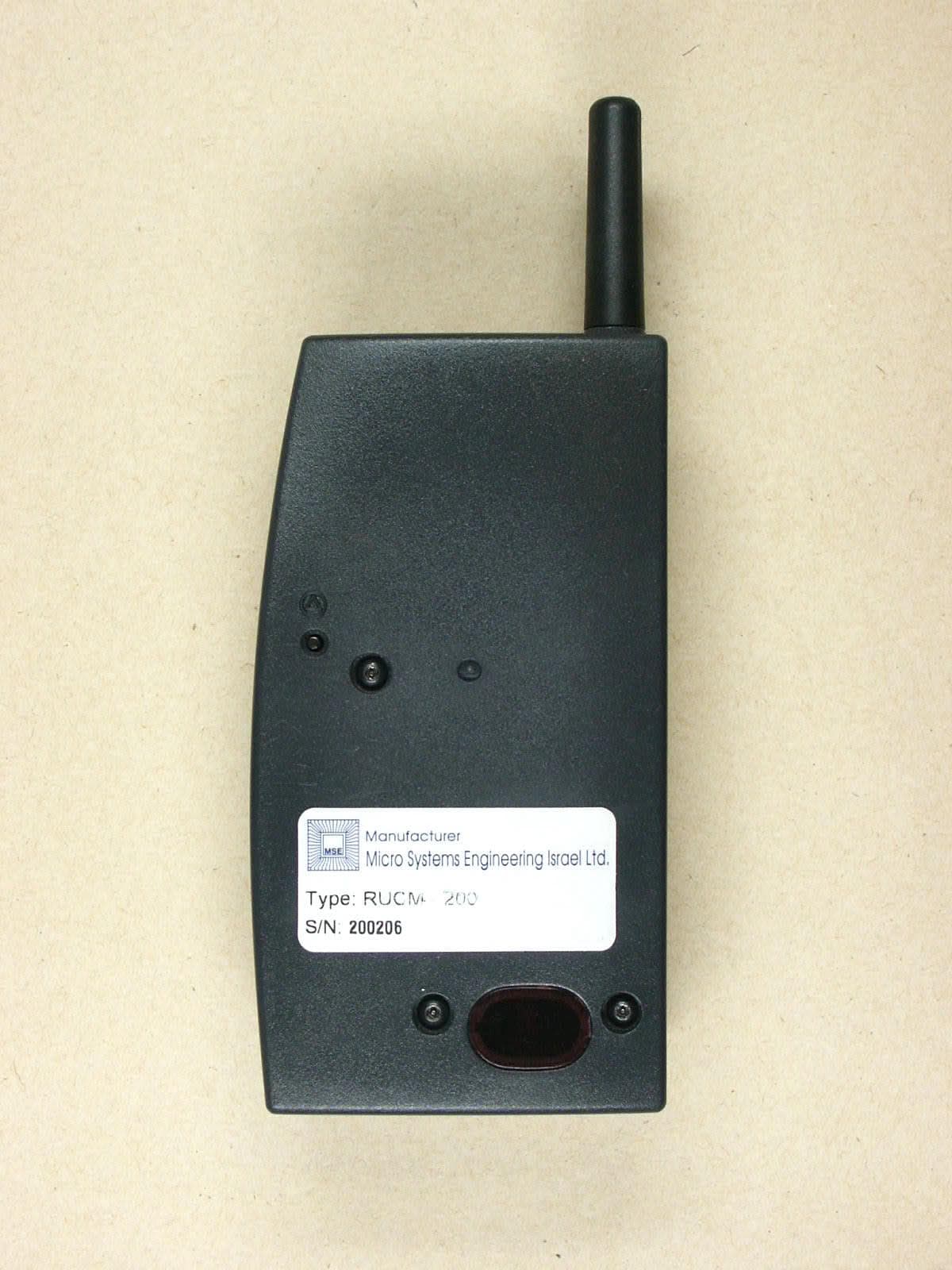
PG6RUCM200
Dec 17, 2002Patient Device
Equipment Class
PCT - PCS Licensed Transmitter worn on body