PG6RUCM200Patient Device
Biotronik, Inc.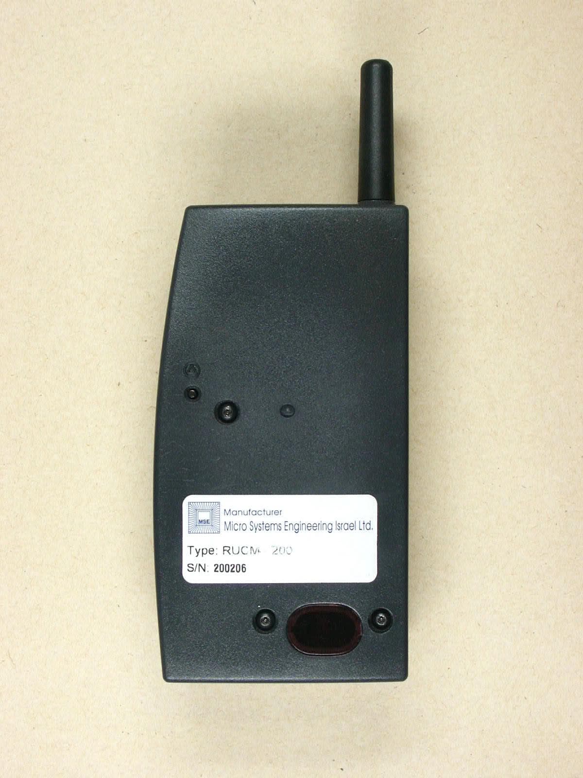
Click to zoom
Application Details
- Equipment Class
- PCT - PCS Licensed Transmitter worn on body
- Date of Grant
- Dec 17, 2002
- Application Purpose
- Original Equipment
- Date of Application
- Dec 17, 2002
- Equipment Note
- Patient Device
- Frequency Range
- 1850.20000000 - 1909.80000000
- Company
- Biotronik, Inc.
- Country
- United States
Documents & Files
Document Text
Text extracted from the exhibit documents filed with the FCC. Open a document above to read the original.
Users Manual
Brochure for patients using the Home Monitoring Patient Device ContentsContents ContentsContents Contents Page What is Home Monitoring? 2 How does the patient device work? 4 Safety precautions –what to look out for 5 How to handle the patient device8 How do I turn my mobile patient device on?10 How do I turn my mobile patient device off?11 When does my implant transmit messages?14 How do I take care of the device?15 Frequently asked questions by patients16 Technical terms and abbreviations18 Electronic Article Surveillance (EAS) Systems18 Regulatory Aspects19 Technical data21 1 Throughout this manual many references are made to “your doctor” for simplicity purposes. If you have a number of doctors, these references are for the specific doctor that follows your implanted device, pacemaker or defibrillator. What is Home Monitoring?What is Home Monitoring? What is Home Monitoring?What is Home Monitoring? What is Home Monitoring? Dear Patient, You are the recipient of an implanted pacemaker (PM) or Implantable Cardioverter Defibrillator (ICD). Your implant is a complex electronic device, which benefits your health and improves your quality of life. BIOTRONIK has developed a new feature for your implant called, the Home Monitoring function.the Home Monitoring function. the Home Monitoring function.the Home Monitoring function. the Home Monitoring function. The Home Monitoring function permits implant-related monitoring by your doctor. Therefore, an optimal adaption of the implant to your personal and physical needs is possible. Your implanted device has a small wireless transmitter that sends out signals, which have been recorded by the device. A patient device, provided to you for home use, receives these signals from the implant and transmits them to a BIOTRONIK Service Center. The implant data are com- piled at the Service Center in a comprehensive report known as the Cardio Report. Service CenterService Center Service CenterService Center Service Center 2 The Cardio Report is sent to your doctor via FAX at certain predetermined periods decided upon by your doctor. Your doctor can then decide whether your implant settings should be optimized or if the therapy schedule should be changed. If necessary, he or she will contact you about an appointment for a follow-up examination to optimize your pacemaker or ICD. Because of the restricted transmission range of your implant’s wireless transmitter, the patient device is re- quired for receiving and forwarding the implant data. If your patient device is not operational or too farIf your patient device is not operational or too far If your patient device is not operational or too farIf your patient device is not operational or too far If your patient device is not operational or too far away from your implant, it does not affect the opera-away from your implant, it does not affect the opera- away from your implant, it does not affect the opera-away from your implant, it does not affect the opera- away from your implant, it does not affect the opera- tion of your implanted device. tion of your implanted device. tion of your implanted device. tion of your implanted device. tion of your implanted device. In this case, your implant still “works” as usual. Only the Home Monitoring function is inactive. This means that messages can not be trans- mitted to the patient device and forwarded to the Service Center. The messages recorded by the implant can still be transmitted and evaluated during a regular follow-up examination. Your doctor will answer any further ques- tions. On the following pages you will learn interesting facts about the patient device and how to handle it. 3 How does the patient device work?How does the patient device work? How does the patient device work?How does the patient device work? How does the patient device work? BIOTRONIK has developed a mobile patient device which can always be taken with you to ensure that your personal freedom and mobility are restricted as little as possible. The patient unit consists of the following components: •Mobile Patient device with internal batteries •Charging stand with power supply set The mobile patient device works similarly to a cellular telephone and transmits the messages received from the implant using the Short Message System (SMS). These digital messages are sent from the patient device to a BIOTRONIK Service Center. Once fully charged, the built- in batteries ensure approximately 15 hours of operating time. The mobile patient device remains operational while placed on the charging stand. LED mobile patient deviceLED mobile patient device LED mobile patient deviceLED mobile patient device LED mobile patient device LED charging standLED charging stand LED charging standLED charging stand LED charging stand 4 On/Off buttonOn/Off button On/Off buttonOn/Off button On/Off button Safety precautions – What to look out forSafety precautions – What to look out for Safety precautions – What to look out forSafety precautions – What to look out for Safety precautions – What to look out for The patient device and its components were developed, produced and tested according to the latest guidelines and standards. It meets the strict regulations for medical devices. So that your patient device functions without problems, the following safety measures must be carried out: Do not use the patient device in areas where a cellularDo not use the patient device in areas where a cellular Do not use the patient device in areas where a cellularDo not use the patient device in areas where a cellular Do not use the patient device in areas where a cellular phone is forbidden – hospitals, aircraftphone is forbidden – hospitals, aircraft phone is forbidden – hospitals, aircraftphone is forbidden – hospitals, aircraft phone is forbidden – hospitals, aircraft ,, ,, , etc etc etc etc etc .. .. . Switch your patient device off before you enter areas where cellular phones are forbidden. !! !! ! !! !! ! Keep a minimum dis…
Text truncated - open the document above for the full version.
Cover Letter(s)
Federal Communications Commission Authorization and Evaluation Division Equipment Authorization Branch 7435 Oakland Mills Road Columbia, MD 21046 Applicant’s statement FCC ID: PG6RUCM200 To whom it may concern; The analog transceiver is a receiver only. There is only one band for GSM. Biotronik, Inc. 624 SW Jean Road Lake Oswego, OR 97035 USA March 12, 2003 Jim Horton Sr. Program Manager-Home Monitoring BIOTRONIK USA
External Photos
ELECTRONIC TECHNOLOGY SYSTEMS DR.GENZ GMBH ETS Dr. Genz GmbH, GermanyRegistration number: G0M20205-6625-T-47Page 1 of 13 Appendix A. Pictures ELECTRONIC TECHNOLOGY SYSTEMS DR.GENZ GMBH ETS Dr. Genz GmbH, GermanyRegistration number: G0M20205-6625-T-47Page 2 of 13 ELECTRONIC TECHNOLOGY SYSTEMS DR.GENZ GMBH ETS Dr. Genz GmbH, GermanyRegistration number: G0M20205-6625-T-47Page 3 of 13 ELECTRONIC TECHNOLOGY SYSTEMS DR.GENZ GMBH ETS Dr. Genz GmbH, GermanyRegistration number: G0M20205-6625-T-47Page 4 of 13
ID Label/Location Info
Type: RUCM – 200 S/N: 12345678 FCC ID: PG6RUCM200L1424-C 3/03 Type: RUCM – 200 S/N: 12345678 FCC ID: PG6RUCM200L1424-C 3/03 Type: RUCM – 200 S/N: 12345678 FCC ID: PG6RUCM200L1424-C 3/03 Type: RUCM – 200 S/N: 12345678 FCC ID: PG6RUCM200L1424-C 3/03 Type: RUCM – 200 S/N: 12345678 FCC ID: PG6RUCM200L1424-C 3/03 Type: RUCM – 200 S/N: 12345678 FCC ID: PG6RUCM200L1424-C 3/03 Type: RUCM – 200 S/N: 12345678 FCC ID: PG6RUCM200L1424-C 3/03 Type: RUCM – 200 S/N: 12345678 FCC ID: PG6RUCM200L1424-C 3/03 Type: RUCM – 200 S/N: 12345678 FCC ID: PG6RUCM200L1424-C 3/03 Type: RUCM – 200 S/N: 12345678 FCC ID: PG6RUCM200L1424-C 3/03 Type: RUCM – 200 S/N: 12345678 FCC ID: PG6RUCM200L1424-C 3/03 Type: RUCM – 200 S/N: 12345678 FCC ID: PG6RUCM200L1424-C 3/03 Type: RUCM – 200 S/N: 12345678 FCC ID: PG6RUCM200L1424-C 3/03 Type: RUCM – 200 S/N: 12345678 FCC ID: PG6RUCM200L1424-C 3/03 Type: RUCM – 200 S/N: 12345678 FCC ID: PG6RUCM200L1424-C 3/03 Type: RUCM – 200 S/N: 12345678 FCC ID: PG6RUCM200L1424-C 3/03 Type: RUCM – 200 S/N: 12345678 FCC ID: PG6RUCM200L1424-C 3/03 Type: RUCM – 200 S/N: 12345678 FCC ID: PG6RUCM200L1424-C 3/03 Type: RUCM – 200 S/N: 12345678 FCC ID: PG6RUCM200L1424-C 3/03 Type: RUCM – 200 S/N: 12345678 FCC ID: PG6RUCM200L1424-C 3/03 Type: RUCM – 200 S/N: 12345678 FCC ID: PG6RUCM200L1424-C 3/03 Type: RUCM – 200 S/N: 12345678 FCC ID: PG6RUCM200L1424-C 3/03 Type: RUCM – 200 S/N: 12345678 FCC ID: PG6RUCM200L1424-C 3/03 Type: RUCM – 200 S/N: 12345678 FCC ID: PG6RUCM200L1424-C 3/03 Type: RUCM – 200 S/N: 12345678 FCC ID: PG6RUCM200L1424-C 3/03 Type: RUCM – 200 S/N: 12345678 FCC ID: PG6RUCM200L1424-C 3/03 Type: RUCM – 200 S/N: 12345678 FCC ID: PG6RUCM200L1424-C 3/03 Type: RUCM – 200 S/N: 12345678 FCC ID: PG6RUCM200L1424-C 3/03 Type: RUCM – 200 S/N: 12345678 FCC ID: PG6RUCM200L1424-C 3/03 Type: RUCM – 200 S/N: 12345678 FCC ID: PG6RUCM200L1424-C 3/03
Internal Photos
ELECTRONIC TECHNOLOGY SYSTEMS DR.GENZ GMBH ETS Dr. Genz GmbH, GermanyRegistration number: G0M20205-6625-T-47Page 5 of 13 ELECTRONIC TECHNOLOGY SYSTEMS DR.GENZ GMBH ETS Dr. Genz GmbH, GermanyRegistration number: G0M20205-6625-T-47Page 6 of 13 ELECTRONIC TECHNOLOGY SYSTEMS DR.GENZ GMBH ETS Dr. Genz GmbH, GermanyRegistration number: G0M20205-6625-T-47Page 7 of 13 ELECTRONIC TECHNOLOGY SYSTEMS DR.GENZ GMBH ETS Dr. Genz GmbH, GermanyRegistration number: G0M20205-6625-T-47Page 8 of 13 ELECTRONIC TECHNOLOGY SYSTEMS DR.GENZ GMBH ETS Dr. Genz GmbH, GermanyRegistration number: G0M20205-6625-T-47Page 9 of 13 ELECTRONIC TECHNOLOGY SYSTEMS DR.GENZ GMBH ETS Dr. Genz GmbH, GermanyRegistration number: G0M20205-6625-T-47Page 10 of 13
RF Exposure Info
PCTEST ENGINEERING LABORATORY, INC. 6660 — B Dobbin Road • Columbia, MD 21045 • USA Telephone 410.290.6652 / Fax 410.290.6654 http://www.pctestlab.com (email: [email protected]) CERTIFICATE OF COMPLIANCE (SAR EVALUATION) PCTEST SAR REPORT FCC CERTIFICATION Reviewed by: Quality Manager SAR Filename: SAR-220627338.PG6 Test Dates: June 27, 2002 EUT Type: GSM Medical Device FCC ID: PG6RUCM200 Page 1 of 22 © 2002 PCTEST Engineering Laboratory, Inc APPLICANT NAME & ADDRESS: DATE & LOCATION OF TESTING: BIOTRONIK, INC. Dates of Tests: June 27, 2002 6024 SW Jean Rd., Bldg. B Test Report S/N: SAR.220627338.PG6 Lake Oswego, OR 97035 Test Site: PCTEST Lab, Columbia, MD USA Attn: Mr. Mark Johnson FCC ID: PG6RUCM200 APPLICANT: BIOTRONIK, INC. EUT Type: GSM Medical Emergency Device Tx Frequency: 1850.2 — 1909.8 MHz (PCS GSM) Rx Frequency: 1930.2 — 1989.8 MHz (PCS GSM) Max. RF Output Power: 0.98 W EIRP PCS GSM / 29.9 dBm Conducted Max. SAR Measurement: 0.690W/kg PCS GSM Body SAR Trade Name/Model(s): RUCM-200 FCC Classification: Licensed Portable Transmitter Worn on Body (PCT) FCC Rule Part(s): §2.1093; FCC/OET Bulletin 65 Supplement C [July 2001] Application Type: Certification Test Device Serial No.: identical prototype This wireless portable device has been shown to be capable of compliance for localized specific absorption rate (SAR) for uncontrolled environment/general population exposure limits specified in ANSI/IEEE Std. C95.1-1992 and had been tested in accordance with the measurement procedures specified in FCC/OET Bulletin 65 Supplement C (2001) and IEEE Std. 1528-200X (Draft 6.4, July 2001). I attest to the accuracy of data. All measurements reported herein were performed by me or were made under my supervision and are correct to the best of my knowledge and belief. I assume full responsibility for the completeness of these measurements and vouch for the qualifications of all persons taking them. PCTEST certifies that no party to this application has been denied the FCC benefits pursuant to Section 5301 of the Anti-Drug Abuse Act of 1988, 21 U.S.C. 862. 220627338.PG6 PCTEST SAR REPORT FCC CERTIFICATION Reviewed by: Quality Manager SAR Filename: SAR-220627338.PG6 Test Dates: June 27, 2002 EUT Type: GSM Medical Device FCC ID: PG6RUCM200 Page 2 of 22 © 2002 PCTEST Engineering Laboratory, Inc TABLE OF CONTENTS 1. INTRODUCTION .................................................................................................. 3 SAR DEFINITION ................................................................................................. 3 2. SAR MEASUREMENT SETUP .................................................................................. 4 Robotic System ....................................................................................................... 4 System Hardware ................................................................................................... 4 System Electronics .................................................................................................. 4 3. DASY3 E-FIELD PROBE SYSTEM ............................................................................ 5 Probe Measurement System.................................................................................... 5 Probe Specifications ............................................................................................... 5 4. Probe Calibration Process....................................................................................... 6 Dosimetric Assessment Procedure .......................................................................... 6 Free Space Assessment ........................................................................................... 6 Temperature Assessment ........................................................................................ 6 5. PHANTOM & EQUIVALENT TISSUES .................................................................... 7 SAM Phantom ........................................................................................................ 7 Brain & Muscle Simulating Mixture Characterization ............................................. 7 Device Holder for Transmitters............................................................................... 7 6. TEST SYSTEM SPECIFICATIONS ............................................................................. 8 Automated Test System Specifications .................................................................... 8 7. DOSIMETRIC ASSESSMENT & PHANTOM SPECS ................................................. 9 Measurement Procedure......................................................................................... 9 Specific Anthropomorphic Mannequin (SAM) Specifications.................................. 9 8. DEFINITION OF REFERENCE POINTS ................................................................. 10 EAR Reference Point............................................................................................. 10 Handset Reference Points ..................................................................................... 10 9. TEST CONFIGURATION POSITIONS .................................................................. 11 Positioning for Cheek/Touch ................................................................................ 11 Positioning for Ear / 15° Tilt .................................................................................. 12 Body Holster /Belt Clip Configurations ................................................................. 13 10. ANSI/IEEE C95.1 - 1992 RF EXPOSURE LIMITS ................................................... 14 Uncontrolled Environment ................................................................................... 14 Controlled Environment........................................................................................ 14 11. MEASUREMENT UNCERTAINTIES ....................................................................... 15 SAR …
Text truncated - open the document above for the full version.
RF Exposure Info
BIOTRONIK FCC ID: PG6RUCM200-- PCS GSM Body SAR SAM Phantom; Flat Section; Probe:ET3DV6 - SN1677; ConvF(4.90,4.90,4.90) Med. Parameters 1900 MHz Muscle: σ = 1.54 mho/m ε r = 53.9 ρ = 1.00 g/cm 3 ; Antenna Position -- Out; Crest Factor 8.0 SAR (1g): 0.187 mW/g, SAR (10g): 0.105 mW/g BIOTRONIK 1900MHz PCS/GSM Model: RUCM-200 Channel.512 [1850.2]; Standard Battery; Ambient Temp. = 22.3°C / Meas. Tissue Temp. = 22.1°C Conducted Power = 29.9dBm; Spacing = 0.5cm from back of EUT [antenna side] w/Holster Test Date -- 06/27/2002 [FCC/OET Bulletin 65 - Supplement C, July 2001] SAR Tot [mW/g] 1.62E-2 4.86E-2 8.10E-2 1.13E-1 1.46E-1 PCTEST Engineering Laboratory, Inc. BIOTRONIK FCC ID: PG6RUCM200-- PCS GSM Body SAR SAM Phantom; Flat Section; Probe:ET3DV6 - SN1677; ConvF(4.90,4.90,4.90) Med. Parameters 1900 MHz Muscle: σ = 1.54 mho/m ε r = 53.9 ρ = 1.00 g/cm 3 ; Antenna Position -- Out; Crest Factor 8.0 SAR (1g): 0.173 mW/g, SAR (10g): 0.0962 mW/g BIOTRONIK 1900MHz GSM Model: RUCM-200 Channel: 661 [1880.0]; Standard Battery; Ambient Temp. = 22.3°C / Meas. Tissue Temp. = 22.1°C Conducted Power = 29.9dBm; Spacing = 0.5cm from back of EUT [antenna side] w/Holster Test Date -- 06/27/2002 [FCC/OET Bulletin 65 - Supplement C, July 2001] SAR Tot [mW/g] 1.49E-2 4.47E-2 7.45E-2 1.04E-1 1.34E-1 PCTEST Engineering Laboratory, Inc. BIOTRONIK FCC ID: PG6RUCM200-- PCS GSM Body SAR SAM Phantom; Flat Section; Probe:ET3DV6 - SN1677; ConvF(4.90,4.90,4.90) Med. Parameters 1900 MHz Muscle: σ = 1.54 mho/m ε r = 53.9 ρ = 1.00 g/cm 3 ; Antenna Position -- Out; Crest Factor 8.0 SAR (1g): 0.120 mW/g, SAR (10g): 0.0660 mW/g BIOTRONIK 1900MHz GSM Model: RUCM-200 Channel: 810 [1909.8]; Standard Battery; Ambient Temp. = 22.3°C / Meas. Tissue Temp. = 22.1°C Conducted Power = 30.0dBm; Spacing = 0.5cm from back of EUT [antenna side] w/Holster Test Date -- 06/27/2002 [FCC/OET Bulletin 65 - Supplement C, July 2001] SAR Tot [mW/g] 1.06E-2 3.18E-2 5.30E-2 7.42E-2 9.54E-2 PCTEST Engineering Laboratory, Inc. BIOTRONIK FCC ID: PG6RUCM200-- PCS GSM Body SAR SAM Phantom; Flat Section; Probe:ET3DV6 - SN1677; ConvF(4.90,4.90,4.90) Med. Parameters 1900 MHz Muscle: σ = 1.54 mho/m ε r = 53.9 ρ = 1.00 g/cm 3 ; Antenna Position -- Out; Crest Factor 8.0 SAR (1g): 0.595 mW/g, SAR (10g): 0.295 mW/g BIOTRONIK 1900MHz GSM Model: RUCM-200 Channel: 512 [1850.2]; Standard Battery; Ambient Temp. = 22.3°C / Meas. Tissue Temp. = 22.1°C Conducted Power = 29.9dBm; Spacing = 0.5cm from Front of EUT [Flip Antenna side] w/Holster Test Date -- 06/27/2002 [FCC/OET Bulletin 65 - Supplement C, July 2001] SAR Tot [mW/g] 5.49E-2 1.65E-1 2.75E-1 3.84E-1 4.94E-1 PCTEST Engineering Laboratory, Inc. BIOTRONIK FCC ID: PG6RUCM200-- PCS GSM Body SAR SAM Phantom; Flat Section; Probe:ET3DV6 - SN1677; ConvF(4.90,4.90,4.90) Med. Parameters 1900 MHz Muscle: σ = 1.54 mho/m ε r = 53.9 ρ = 1.00 g/cm 3 ; Antenna Position -- Out; Crest Factor 8.0 SAR (1g): 0.690 mW/g, SAR (10g): 0.349 mW/g * Max outside BIOTRONIK 1900MHz GSM Model: RUCM-200 Channel: 661 [1880.0]; Standard Battery; Ambient Temp. = 22.3°C / Meas. Tissue Temp. = 22.1°C Conducted Power = 29.9dBm; Spacing = 0.5cm from Front of EUT [Flip Antenna side] w/Holster Test Date -- 06/27/2002 [FCC/OET Bulletin 65 - Supplement C, July 2001] SAR Tot [mW/g] 6.79E-2 2.04E-1 3.40E-1 4.75E-1 6.11E-1 PCTEST Engineering Laboratory, Inc. BIOTRONIK FCC ID: PG6RUCM200-- PCS GSM Body SAR SAM Phantom; Flat Section; Probe:ET3DV6 - SN1677; ConvF(4.90,4.90,4.90) Med. Parameters 1900 MHz Muscle: σ = 1.54 mho/m ε r = 53.9 ρ = 1.00 g/cm 3 ; Antenna Position -- Out; Crest Factor 8.0 SAR (1g): 0.577 mW/g, SAR (10g): 0.292 mW/g * Max outside BIOTRONIK 1900MHz GSM Model: RUCM-200 Channel: 810 [1909.8]; Standard Battery; Ambient Temp. = 22.3°C / Meas. Tissue Temp. = 22.1°C Conducted Power = 29.9dBm; Spacing = 0.5cm from Front of EUT [Flip Antenna side] w/Holster Test Date -- 06/27/2002 [FCC/OET Bulletin 65 - Supplement C, July 2001] SAR Tot [mW/g] 6.02E-2 1.81E-1 3.01E-1 4.21E-1 5.42E-1 PCTEST Engineering Laboratory, Inc.
RF Exposure Info
1900MHz Brain Dipole Validation Sam Phantom; Flat Section; Probe: ET3DV6 - SN1677; ConvF(5.30,5.30,5.30) Probe Cal Date 04/10/02 Med. Parameters 1900 MHz Brain: σ = 1.41 mho/m ε r = 40.6 ρ = 1.00 g/cm 3 ; Antenna Position -- Out; Crest Factor 1.0 SAR (1g): 9.37 mW/g, SAR (10g): 4.78 mW/g 1900MHz Brain Dipole Validation (D1900V2 S/N: 502) Frequency: 1900 MHz; Antenna Input Power: 250 [mW]; Ambient Temp. = 22.3 °C / Meas. Tissue Temp. = 22.1°C PCTEST Brain Tissue Simulating Liquid [06/27/2002] SAR Tot [mW/g] 9.12E-1 2.71E+0 4.62E+0 6.35E+0 8.22E+0 PCTEST Engineering Laboratory, Inc.
RF Exposure Info
© 2002 PCTEST Lab BIOTRONIK FCC ID: PG6RUCM200 GSM Medical Emergency Device (Model: RUCM-200) © 2002 PCTEST Lab BIOTRONIK FCC ID: PG6RUCM200 GSM Medical Emergency Device (Model: RUCM-200) © 2002 PCTEST Lab BIOTRONIK FCC ID: PG6RUCM200 GSM Medical Emergency Device (Model: RUCM-200) © 2002 PCTEST Lab BIOTRONIK FCC ID: PG6RUCM200 GSM Medical Emergency Device (Model: RUCM-200) © 2002 PCTEST Lab BIOTRONIK FCC ID: PG6RUCM200 GSM Medical Emergency Device (Model: RUCM-200) © 2002 PCTEST Lab BIOTRONIK FCC ID: PG6RUCM200 GSM Medical Emergency Device (Model: RUCM-200)
RF Exposure Info
© 2002 PCTEST Lab BIOTRONIK FCC ID: PG6RUCM200 GSM Medical Emergency Device (Model: RUCM-200) © 2002 PCTEST Lab BIOTRONIK FCC ID: PG6RUCM200 GSM Medical Emergency Device (Model: RUCM-200) © 2002 PCTEST Lab BIOTRONIK FCC ID: PG6RUCM200 GSM Medical Emergency Device (Model: RUCM-200) © 2002 PCTEST Lab BIOTRONIK FCC ID: PG6RUCM200 GSM Medical Emergency Device (Model: RUCM-200) © 2002 PCTEST Lab BIOTRONIK FCC ID: PG6RUCM200 GSM Medical Emergency Device (Model: RUCM-200)
RF Exposure Info
© 2002 PCTEST Lab BIOTRONIK FCC ID: PG6RUCM200 GSM Medical Emergency Device (Model: RUCM-200) © 2002 PCTEST Lab BIOTRONIK FCC ID: PG6RUCM200 GSM Medical Emergency Device (Model: RUCM-200) © 2002 PCTEST Lab BIOTRONIK FCC ID: PG6RUCM200 GSM Medical Emergency Device (Model: RUCM-200) © 2002 PCTEST Lab BIOTRONIK FCC ID: PG6RUCM200 GSM Medical Emergency Device (Model: RUCM-200) © 2002 PCTEST Lab BIOTRONIK FCC ID: PG6RUCM200 GSM Medical Emergency Device (Model: RUCM-200) © 2002 PCTEST Lab BIOTRONIK FCC ID: PG6RUCM200 GSM Medical Emergency Device (Model: RUCM-200) © 2002 PCTEST Lab BIOTRONIK FCC ID: PG6RUCM200 GSM Medical Emergency Device (Model: RUCM-200) © 2002 PCTEST Lab BIOTRONIK FCC ID: PG6RUCM200 GSM Medical Emergency Device (Model: RUCM-200)
Test Report
ELECTRONIC TECHNOLOGY SYSTEMS DR. GENZ GMBH TEST - REPORT FCC RULES PART 24 Test report no.: G0M20205-6625-T-48 FCC ELECTRONIC TECHNOLOGY SYSTEMSSTORKOWER STRASSE 38C, D-15526 REICHENWALDE B. BERLIN DR. GENZ GMBHPHONE +49-33631-888 00 FAX +49-33631-888 66 ETS Dr. Genz GmbH, GermanyRegistration number: G0M20205-6625-T-48Page 1 of 22 ELECTRONIC TECHNOLOGY SYSTEMS DR.GENZ GMBH TABLE OF CONTENTS 1General information 1.1Notes 1.2Testing laboratory 1.3Details of approval holder 1.4Application details 1.5Test item 1.6Test standards 2Technical test 2.1Summary of test results 2.2Test environment 2.3Test equipment utilized 3 Test Results 4 RF Power Output, FCC 2.1046 4.1 Test Procedure 4.2 Test Results 5 Radiated Power, FCC 24.232 5.1 Test Procedure 5.2 Test Results 6 Occupied Bandwidth, FCC 2.1049 6.1 Test Procedure 6.2 Test Results 7 Field Strength of Spurious Radiations, FCC 2.1053, 24.238 7.1 Test Procedure 7.2 Test Results 8 Line Conducted Emissions, FCC 15.107 8.1 Test Procedure 8.2 Test Results 9 Frequency Stability vs Temperature, FCC 2.1055, 24.235 9.1 Test Procedure 9.2 Test Results 10 Frequency Stability vs Voltage, FCC 2.1055, 24.235 10.1 Test Procedure 10.2 Test Equipment ETS Dr. Genz GmbH, GermanyRegistration number: G0M20205-6625-T-48Page 2 of 22 ELECTRONIC TECHNOLOGY SYSTEMS DR.GENZ GMBH 1General Information 1.1Notes The purpose of conformity testing is to increase the probability of adherence to the essential requirements or conformity specifications, as appropriate. The complexity of the technical specifications, however, means that full and thorough testing is impractical for both technical and economic reasons. Furthermore, there is no guarantee that a test sample which has passed all the relevant tests conforms to a specification. Neither is there any guarantee that such a test sample will interwork with other genuinely open systems. The existence of the tests nevertheless provides the confidence that the test sample possesses the qualities as maintained and that is performance generally conforms to representative cases of communications equipment. The test results of this test report relate exclusively to the item tested as specified in 1.5. The test report may only be reproduced or published in full. Reproduction or publication of extracts from the report requires the prior written approval of the ELECTRONIC TECHNOLOGY SYSTEMS DR. GENZ GMBH. Tester: 26.11.2002Mr. Schulz DateETS-Lab.NameSignature Technical responsibility for area of testing: 26.11.2002Dr. Genz DateETSNameSignature ETS Dr. Genz GmbH, GermanyRegistration number: G0M20205-6625-T-48Page 3 of 22 ELECTRONIC TECHNOLOGY SYSTEMS DR.GENZ GMBH 1.2 Testing laboratory 1.2.1Location ELECTRONIC TECHNOLOGY SYSTEM DR. GENZ GMBH (ETS) Storkower Straße 38c D-15526 Reichenwalde b. Berlin Germany Telefon : +49 33631 888 00 Telefax : +49 33631 888 660 1.2.2Details of accreditation status A CCREDITED TESTING LABORATORY DAR-REGISTRATION NUMBER: TTI-P-G 126/96 ACCREDITED COMPETENT BODY DAR-REGISTRATION NUMBER: BPT-ZE-026/96 FCC FILED TEST LABORATORY REG. NO. 96970 BLUETOOTH QUALIFICATION TEST FACILITY (BQTF) ACCREDITED BY: BLUETOOTH QUALIFICATION REVIEW BOARD (BQRF) I NDUSTRY CANADA FILED TEST LABORATORY REG. NO. IC 3470 A2LA A CCREDITEDCertificate Number: 1983-01 1.3Details of approval holder Name: Biotronik, Inc. Street: 6024 Jean Road Town: Lake Oswego, Oregon, 97035 Country: USA Telephone: 1 800-547-0394 Fax: 1 503-635-9936 Contact: Mr. Mark Johnson Email: [email protected] ETS Dr. Genz GmbH, GermanyRegistration number: G0M20205-6625-T-48Page 4 of 22 ELECTRONIC TECHNOLOGY SYSTEMS DR.GENZ GMBH 1.4Application details Date of receipt of application: 15.05.2002 Date of receipt of test item: 15.05.2002 Date of test: 15.05.2002 – 06.06.2002, 19.11.2002 1.5Test item Description of test item: Home MonitoringPatient Device Type identification: RUCM-200 with RUCL-1000 Charging Station Serial number: Test model without serial number. Photos: See annex A Technical data Frequency range Tx: 1850-1910 MHz Frequency range Rx: 1930-1990 MHz Antenna transmitter: integral (internal antenna) Antenna Gain: Power supply : 7,4 V DC Operating mode: duplex Type of modulation: GMSK (GSM modulation) Emission: GXW Manufacturer: (if applicable) Name: Micro Systems Engineering Inc Street: 6024 Jean Road Town: Lake Oswego, Oregon, 97035 Country: USA Additional information: none ETS Dr. Genz GmbH, GermanyRegistration number: G0M20205-6625-T-48Page 5 of 22 ELECTRONIC TECHNOLOGY SYSTEMS DR.GENZ GMBH 1.6Test standards Technical standard : FCC Parts 24 2Technical test 2.1Summary of test results No deviations from the technical specification(s) were ascertained in the course ý of the tests performed. or The deviations as specified in 2.5 were ascertained in the course of the tests ̈ performed. 2.2Test environment Temperature: 23 o C Relative humidity content: 20 ...75 % Air pressure: 86 ...103 kPa Extreme temperature: -30 / 60 °C ETS Dr. Genz GmbH, GermanyRegistration number: G0M20205-6625-T-48Page 6 of 22 ELECTRONIC TECHNOLOGY SYSTEMS DR.GENZ GMBH 2.3Test equipment utilized No.Measurement device:Type:Manufacturer: ETS 0001Test receiverESHS 10Rohde&Schwarz ETS 0002Test receiverESVPRohde&Schwarz ETS 0003Test receiverESVS 10Rohde&Schwarz ETS 0004Spectrum- and Network-AnalyzerFSMS 26Rohde&Schwarz ETS 0005Test receiverSMV 11MEB ETS 0006Test receiver systemSME 12MEB ETS 0007Spectrum analyzerPSA-65AAvcom ETS 0008AntennaLoop antennaSiemens ETS 0009AntennaLoop antennaMEB ETS 0010AntennaLoop antennaMEB ETS 0011Antennavan Veen/ FrameETS ETS 0012AntennaHK 116Rohde&Schwarz ETS 0013AntennaHL 223Rohde&Schwarz ETS 0014AntennaHL 025Rohde&Schwarz ETS 0015AntennaHL 025Rohde&Schwarz ETS 0016AntennaVHAPSchwarzbeck ETS 0017AntennaVHAPSchwarzbeck ETS 0018AntennaUHAPSchwarzbeck ETS 0019AntennaUHAPSchwarzbeck ETS 0020AntennaDP 21MEB ETS 0021AntennaDP 3MEB ETS 0022AntennaSAS-200/ 521A.H. Systeme / USA ETS 0023AntennaDP 1MEB ETS 0024Antenna mastAF 2MEB ETS 0025Antenna mastAF 2MEB ETS 0026Tri…
Text truncated - open the document above for the full version.
Test Setup Photos
ELECTRONIC TECHNOLOGY SYSTEMS DR.GENZ GMBH ETS Dr. Genz GmbH, GermanyRegistration number: G0M20205-6625-T-47Page 11 of 13 ELECTRONIC TECHNOLOGY SYSTEMS DR.GENZ GMBH ETS Dr. Genz GmbH, GermanyRegistration number: G0M20205-6625-T-47Page 12 of 13 ELECTRONIC TECHNOLOGY SYSTEMS DR.GENZ GMBH ETS Dr. Genz GmbH, GermanyRegistration number: G0M20205-6625-T-47Page 13 of 13
Contact Information
Applicant
Mark Johnson(New Business Development Manager)
Test Firm
Eurofins Product Service GmbHRobert Kschiwan-Kaspar
Technical Specifications
| # | Rule Parts | Frequency Range | Power Output | Emission |
|---|---|---|---|---|
| 1 | 24E | 1.85 GHz - 1.91 GHz | 980.00 mW | 330KGXW |
Other Applications from Biotronik, Inc.
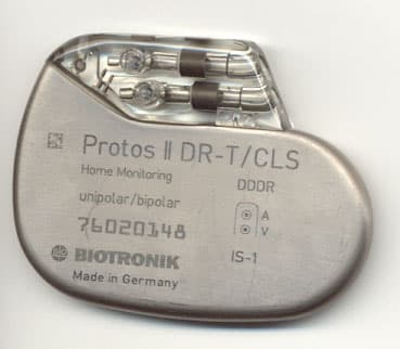
PG6CYLOS
Nov 21, 2005Cylos DR-T
Equipment Class
TNT - Licensed Non-Broadcast Transmitter Worn on Body
PG6BELOS-T
May 06, 2004Belos DR-T, Belos VR-T, and Cardiac Airbag-T
Equipment Class
TNT - Licensed Non-Broadcast Transmitter Worn on Body
PG6LEXOS-T
Dec 21, 2003Lexos DR-T & Lexos VR-T
Equipment Class
TNT - Licensed Non-Broadcast Transmitter Worn on Body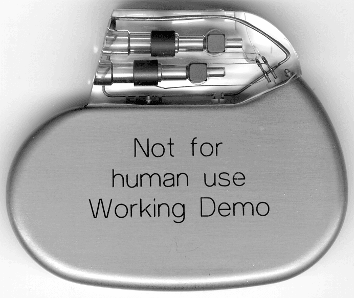
PG6BA0T
Mar 24, 2003Philos DR-T (aka Actros C-T)
Equipment Class
TNT - Licensed Non-Broadcast Transmitter Worn on Body