PG6LEXOS-TLexos DR-T & Lexos VR-T
Biotronik, Inc.
Click to zoom
Application Details
- Equipment Class
- TNT - Licensed Non-Broadcast Transmitter Worn on Body
- Date of Grant
- Dec 21, 2003
- Application Purpose
- Original Equipment
- Date of Application
- Oct 21, 2003
- Equipment Note
- Lexos DR-T & Lexos VR-T
- Frequency Range
- 403.60000000 - 403.60000000
- Company
- Biotronik, Inc.
- Country
- United States
Documents & Files
Document Text
Text extracted from the exhibit documents filed with the FCC. Open a document above to read the original.
Users Manual
Lexos Family of Implantable Cardioverter Defibrillators Technical Manual X-ray Identification Lexos DR, DR-T, VR and VR-T Implantable Cardioverter Defibrillator Inside the housing, right-hand side: X-Ray identification KV Year of manufacture nn C AUTION Federal (U.S.A.) law restricts this device to sale by, or on the order of, a physician. 2003 BIOTRONIK, Inc., all rights reserved. Lexos Technical Manual i Contents 1. General...........................................................................1 1.1 System Description....................................................1 1.2 Indications and Usage...............................................2 1.3 Contraindications .......................................................3 1.4 Warnings and Precautions.........................................3 1.4.1 Sterilization, Storage, and Handling ..................4 1.4.2 Device Implantation and Programming..............4 1.4.3 Lead Evaluation and Connection.......................6 1.4.4 Follow-up Testing...............................................8 1.4.5 Pulse Generator Explant and Disposal..............8 1.4.6 Hospital and Medical Hazards ...........................9 1.4.7 Home and Occupational Hazards......................10 1.4.8 Cellular Phones..................................................11 1.4.9 Electronic Article Surveillance (EAS).................12 1.4.10 Home Appliances...............................................12 1.5 Adverse Events..........................................................13 1.5.1 Potential Adverse Events...................................13 1.5.2 Observed Adverse Events .................................14 1.6 Clinical Studies ..........................................................17 1.6.1 Tachos DR .........................................................17 1.6.2 Phylax AV...........................................................19 1.7 Patient Selection and Treatment ...............................21 1.7.1 Individualization of Treatment ............................21 1.7.2 Specific Patient Populations ..............................22 1.8 Patient Counseling Information .................................23 1.9 Evaluating Prospective ICD Patients.........................23 2. Device Features ............................................................25 2.1 Sensing (Automatic Sensitivity Control) ....................25 2.1.1 Ventricular Sensitivity Settings ..........................25 2.1.2 Minimum Ventricular Threshold .........................28 2.1.3 Atrial Sensitivity Settings....................................28 2.1.4 Minimum Atrial Threshold ..................................29 2.1.5 Far Field Blanking ..............................................29 ii Lexos Technical Manual 2.2 Ventricular Tachyarrhythmia Detection ......................30 2.2.1 VF Classifications ..............................................31 2.2.2 VT Interval Counters ..........................................31 2.2.3 VT Classification ................................................31 2.2.4 SMART Detection™...........................................32 2.2.5 Onset..................................................................33 2.2.6 Stability...............................................................33 2.2.7 Sustained VT Timer ...........................................34 2.3 Tachyarrhythmia Redetection ....................................34 2.3.1 VT Redetection ..................................................35 2.3.2 SMART Redetection..........................................35 2.3.3 VF Redetection ..................................................35 2.4 Tachyarrhythmia Termination.....................................35 2.5 Tachyarrhythmia Therapy ..........................................36 2.5.1 Therapy Options ................................................36 2.5.2 Anti-Tachycardia Pacing (ATP) .........................36 2.5.3 Shock Therapy...................................................39 2.5.4 Progressive Course of Therapy .........................42 2.6 Bradycardia Therapy.................................................43 2.6.1 Bradycardia Pacing Modes ................................43 2.6.2 Basic Rate..........................................................44 2.6.3 Night Rate ..........................................................44 2.6.4 Rate Hysteresis..................................................44 2.6.5 Dynamic AV Delay .............................................48 2.6.6 Upper Tracking Rate..........................................49 2.6.7 Mode Switching..................................................50 2.6.8 PMT Management .............................................51 2.6.9 Rate Adaptive Pacing ........................................51 2.6.10 Pulse Amplitude .................................................53 2.6.11 Pulse Width ........................................................53 2.6.12 Post Ventricular Atrial Refractory Period ...........53 2.6.13 PVARP Extension ..............................................53 2.6.14 Noise Response.................................................54 2.6.15 Post Shock Pacing.............................................54 2.7 EP Test Functions......................................................54 Lexos Technical Manual iii 2.7.1 P and R-wave Amplitude Measurments ............54 2.7.2 Testing for Retrograde Conduction....................55 2.7.3 Pacing Threshold ...............................................56 2.7.4 Arrhythmia Induction Features...........................56 2.7.5 Manual Shock ....................................................57 2.7.6 Manual ATP .......................................................57 2.7.7 Test Shock .........................................................57 2.8 Special Features........................................................58 2.8.1 Detection and Therapy Status ...........................58 2.8.2 Home Monitoring (Lexos DR-T and VR-T Only) 59 2.8.…
Text truncated - open the document above for the full version.
Cover Letter(s)
NORTHWEST EMC, INC. 22975 NW Evergreen Parkway, Suite 400 Hillsboro, OR 97124 October 21, 2003 Dear Application Examiner: On behalf of Biotronik Inc., Northwest EMC Inc is submitting this application for the certification of Biotronik’s Lexos-T series transmitters, FCC ID: PG6LEXOS-T. The Lexos-T series are a family of Implantable Cardiac Defibrillator (ICD) devices. This submission covers two (2) devices, the Lexos DR-T and the Lexos VR-T, both built upon Biotronik’s 4110 substrate. Both devices use Biotronik’s proprietary Home Monitoring technology. The transmitter (bipolar-FSK transmitter), associated antenna, and shielding are identical in both devices. The difference between the devices is in the therapy provided to the heart. The Lexos DR-T provides dual chamber therapy using 4 leads attached to the heart, while the Lexos VR-T provides single chamber therapy using 3 leads. Certification is sought under FCC Part 95 MICS. Your efforts in reviewing this application are greatly appreciated. Best regards, Greg Kiemel, Director of Engineering Northwest EMC, Inc.
Cover Letter(s)
March 06, 2003 Jim Horton Sr.Program Manager-Home Monitoring BIOTRONIK USA
Cover Letter(s)
LAW OFFICES GOLDBERG, GODLES, WIENER & WRIGHT 1229 NINETEENTH STREET, N.W. WASHINGTON, D.C. 20036-2413 HENRY GOLDBERG JOSEPH A. GODLES JONATHAN L. WIENER MICHAEL A. McCOIN BRITA D. STRANDBERG HENRIETTA WRIGHT THOMAS G. GHERARDI, P.C. COUNSEL (202) 429-4900 TELECOPIER: (202) 429-4912 e-mail: [email protected] website: www.g2w2.com October 16th, 2003 BY ELECTRONIC FILING Federal Communications Commission Office of Engineering and Technology Laboratory Division Equipment Authorization Branch 7435 Oakland Mills Road Columbia, MD 21046 Re: Biotronik, Inc. (Grantee Code: PG6) Application for Equipment Authorization (Form 731) For the Lexos T Implantable Cardioverter Defibrillator Medical Implant Device Dear Sir or Madam: Submitted herewith on behalf of Biotronik, Inc. (“Biotronik”), is an application on FCC Form 731 for a new equipment authorization for the Lexos T, Biotronik’s next generation implantable cardioverter defibrillator (“ICD”). This medical implant device will operate pursuant to the Medical Implant Communications (“MICS”) service rules (Part 95, Subpart I) and will transmit operational, diagnostic, and therapeutic information associated with its use by cardiac patients to healthcare professionals via the cellular telephone network. The Lexos T offers a single mode of transmission for which authorization is sought. The device transmits when certain cardiac and technical events are detected by the implant device itself, known as “event messaging.” The Commission has Oct. 16th, 2003 Page 2 determined that this mode of transmission is exempt from the frequency monitoring requirements contained in Section 95.628(a) of the MICS rules. 1 In addition, the Lexos T has the capability of offering regularly scheduled transmissions, which are preprogrammed by the implant patient’s physician. On March 27, 2003, Biotronik sought a waiver of the MICS rules to permit its cardiac implant devices to use preprogrammed regularly scheduled transmissions on a single channel without prior frequency monitoring. As Biotronik’s waiver request remains pending, this application does not seek authorization to use the scheduled transmission mode of the Lexos T device. This application, however, is being submitted without prejudice to Biotronik’s pending waiver request, or with respect to obtaining authorization for the Lexos T’s preprogrammed, regularly scheduled transmissions or for any future Biotronik devices. Please direct questions concerning this application to Mr. James Horton, Senior Program Manager for Biotronik, by e-mail at [email protected] or by phone at (503) 387-2640. Respectfully submitted, Henry Goldberg Attorney for Biotronik, Inc. Attachments cc: Mr. Julius Knapp (w/o attachments) Mr. Bruce Romano (w/o attachments) Mr. James Burtle (w/o attachments) 1 See Letter Order from Bruce A. Franca, Deputy Chief, Office of Engineering and Technology, FCC ID. No. PG6BA0T (Mar. 8, 2002) at 2 (“OET Letter Order”), aff’d, In re Biotronik, Inc., Equipment Authorization for the Medical Implant Communications Service, Memorandum Opinion and Order, 18 FCC Rcd 3027, ¶11 (2003).
Cover Letter(s)
October 21, 2003 Federal Communications Commission Authorization and Evaluation Division 7435 Oakland Mills Road Columbia, Maryland 21046 To Whom It May Concern: Per the provision of 47 CFR 0.459, Biotronik would like to request that some of the information provided in our submission for a license for the RF transmitter embedded in our ICD product remain confidential. The confidential documents in this submission should include: Lexos antenna description.pdf Block diagram and circuit and operational description.pdf Modulation description Lexos Internal photos.pdf Lexos RF schematics.pdf Lexos RF partslist.pdf The reasons for requesting confidentiality of these items are that this transmitter circuitry and its performance are Biotronik proprietary designs. If disclosed, this information would result in substantial competitive harm. Utilizing RF communications in ICDs is a novel approach, which Biotronik seeks to exploit as a competitive advantage. Design and development efforts were substantial, and if provided to competitors would create an unfair market advantage to those gaining the information. Biotronik feels that this feature will provide first-to-market advantage that will provide financial gains of millions of dollars. These gains would be greatly diminished if such proprietary information was made publicly available to competitors. Note: This device is only available through Biotronik employees or it’s associates. The device is typically under Biotronik control until the time of implant. The device has a laser-welded outer housing which can not be opened without risk of damage to the device. It is requested that this information remain proprietary for a period of at least two years, as this is the expected lifecycle of such products. It should also be noted that as this is a medical communications device, Biotronik has designed this implant communications system to meet the patient's privacy regulations provided by the Health Insurance Portability and Accountability Act of 1996 (HIPAA). Digital data transmitted with this system is encrypted using techniques to assure privacy of patient data. Specific information regarding the design of this system is revealed in the schematics, descriptions, and photographs. Disclosure of these documents may reduce the effectiveness of the designs for privacy that Biotronik has developed. If there are any further questions regarding the Biotronik request for confidentiality, please contact Jim Horton at (503) 387-2640 or [email protected]. Sincerely, Jim Horton Senior Project Manager Biotronik, Inc.
External Photos
Lexos External Photos
ID Label/Location Info
FCC ID Labeling Scheme Per 47 CFR 2.926 (e), “Where it is shown that a permanently affixed nameplate is not desirable or is not feasible, an alternative method of positively identifying the equipment may be used if approved by the Commission. The proposed alternative method of identification and the justification for its use must be included with the application for equipment authorization. Note: As an example, a device intended to be implanted within the body of a test animal or person would probably require an alternate method of identification.” Since the EUT is implanted in the human body, the FCC ID will not be applied to outside of the device. Instead, the applicant is proposing the following alternate method of applying the FCC ID number to two locations: 1. The FCC ID, along with the disclosure statement required by 95.1215(a), is in the User Manual (page 103 of the Lexos – see excerpt below). 2. The FCC ID also appears on the package label (see examples below), which is affixed to outside of the shipping box for the EUT. Federal Communications Commission Disclosure The Lexos VR-T/DR-T is equipped with an RF transmitter for wireless communications. This transmitter is authorized by rule under the Medical Implant Communications Service (47 CFR Part 95) and must not cause harmful interference to stations operating in the 400.150 - 406.000 MHz band in the Meteorological Aids (i.e., transmitters and receivers used to communicate weather data), the Meteorological Satellite, or the Earth Exploration Satellite Services and must accept interference that may be caused by such aids, including interference that may cause undesired operation. This transmitter shall be used only in accordance with the FCC Rules governing the Medical Implant Communications Service. Analog and digital voice communications are prohibited. Although this transmitter has been approved by the Federal Communications Commission, there is no guarantee that it will not receive interference or that any particular transmission from this transmitter will be free from interference. The FCC ID number for this device is: PG6LEXOS-T. Lexos DR-T Implantable Cardioverter Defibr illator Order No.: XXX XXX DDDRD, 2 x IS-1/BI, 2 x DF-1 Serial No.: 12345678 Use Before: 99/99/9999 DESCRIPTION: One dual chamber active housing implantable cardioverter defibrillator with two IS-1 connector receptacles and two DF-1 connector receptacles. Lexos DR-T contains Biotronik's Home Monitoring capabilities. Programmable Parameters* Factory Settings Bradycardia Mode OFF Tachycardia Detection OFF Home Monitoring OFF CAUTION: When Shipped, all tachycardia and bradycardia functions are inactive! *See technical manual for detailed specifications. STERILE: Cardioverter Defibrillator as identified and accessories NON-STERILE: Package inserts (documentation), refer to technical manual for additional information. STERILIZATION: This unit has been gas sterilized with ethylene oxide. Sterility cannot be guaranteed if the package has been damaged during transportation. Please examine the package carefully before opening. If it shows any evidence of damage or mishandling, it should be returned immediately to BIOTRONIK. Once the box seal has been broken, title passes to the hospital and a purchase order is required. CAUTION: Recommended Storage Temperature: 5° C - 55° C (41° F - 131° F). CAUTION: ICD and lead systems which do not expressly claim to agree with the IS-1 or DF-1 dimensions generally have to be regarded as incompatible with IS-1 or DF-1 connectors. Consult your BIOTRONIK representative regarding lead-generator compatibility prior to the implantation of an ICD system. CAUTION: Federal (U.S.A.) law restricts this device to sale by, or on the order of, a physician. FCC Statement: Lexos DR-T is equipped with an RF transmitter for wireless communications. This device must not interfere with stations operating in the 400.150 - 406.000 MHz band in the Meteorological Satellite or Earth Exploration Satellite Services and must accept any interference received, including interference that may cause undesired operation. Made in Germany B1157-A 11/02 MftN/NBIOTRONIK/004 MftN/NBIOTRONIK/004 Lexos VR-T Implantable Cardioverter Defibr illator Order No.: XXX XXX VVIRD, IS-1/BI, 2 x DF-1 Serial No.: 12345678 Use Before: 99/99/9999 DEVICE DESCRIPTION: One single chamber, rate adaptive implantable cardioverter defibrillator with active housing and with one IS-1 connector receptacle and two DF-1 connector receptacles. Lexos VR-T contains Biotronik's Home Monitoring capabilities. Programmable Parameters* Factory Settings Bradycardia Mode OFF Tachycardia Detection OFF Home Monitoring OFF CAUTION: When shipped, all tachycardia and bradycardia functions are inactive! *See technical manual for detailed specifications. STERILE: Cardioverter Defibrillator as identified and accessories NON-STERILE: Package inserts (documentation), refer to technical manual for additional information. STERILIZATION: This unit has been gas sterilized with ethylene oxide. Sterility cannot be guaranteed if the package has been damaged during transportation. Please examine the package carefully before opening. If it shows any evidence of damage or mishandling, it should be returned immediately to BIOTRONIK. Once the box seal has been broken, title passes to the hospital and a purchase order is required. CAUTION: Recommended Storage Temperature: 5° C - 55° C (41° F - 131° F). CAUTION: ICD and lead systems which do not expressly claim to agree with the IS-1 or DF-1 dimensions generally have to be regarded as incompatible with IS-1 or DF-1 connectors. Consult your BIOTRONIK representative regarding lead-generator compatibility prior to the implantation of an ICD system. CAUTION: Federal (U.S.A.) law restricts this device to sale by, or on the order of, a physician. FCC Statement: ( FCC ID PG6LEXOS-T) Lexos VR-T is equipped with an RF transmitter for wireless communications. This device must not inter…
Text truncated - open the document above for the full version.
Parts List/Tune Up Info
Tune-up Procedure “Describe the Tune-up procedure over the power range, or at specific operating power levels.” There are no tunable elements in the transmitter and no tune up procedure.
RF Exposure Info
Specific Absorption Rate (SAR) Analysis Using Finite Difference Time Domain Computation for RF Transmitter Circuit Employed in Biotronik Lexos “T” Implantable Cardiac Defibrillators October 7, 2003 Introduction Biotronik has developed an RF communications system for use in implantable pacemakers and Implantable Cardiac Defibrillators (ICDs) allowing for patient data regarding cardiac condition to be transmitted wirelessly to the physician for evaluation. The amount of irradiated power transmitted through the human body using this technology can be defined by a measure termed the Specific Absorption Rate (SAR). Values of SAR that can be safely used in these applications have been defined by ANSI/IEEE and are part of the FCC guidelines for medical implant communications. Certification of medical-implant transmitters under the FCC Part 95 Medical Implant Communication Service (MICS) requires a measurement or Finite Difference Time Domain (FDTD) analysis of the SAR associated with the presence of a non-ionizing, radio frequency (RF) transmitter. This report details the SAR analysis of the unidirectional RF transmitter found in Biotro nik’s Lexos “T” family of ICDs. Biotronik performed this analysis on a previous implantable devices designated as the BA03 DDDR pacemaker and the Belos “T” family of ICDs. The analyses for these devices were performed using a FDTD tool and the equipment authorization for these devices are listed under FCC identifiers PG6BA0T and PG6BELOS-T. The RF circuit utilized in Lexos ICD is directly comparable to the BA03 pacemaker and Belos “T”. Summary Using a commercially available FDTD program (XFDTD, Remcom Inc.), the computed SAR values determined by this analysis are: Maximum SAR 277 mW/kg Maximum 1 gm average SAR 2.9 mW/kg Maximum 10 gm average SAR 951 μW/kg Average SAR 99 μW/kg The ANSI C95-1-1992 limit is 1.6 W/kg. The computed value in this study of the maximum SAR in a 1 gram average is 2.9 mW/kg. The margin between the maximum attained SAR and the ANSI/IEEE specification limit is 27.4 dB (only 0.18 % of the specification limit). An uncertainty analysis (worst case) of this computation (detailed in Appendix A) subtracts 3.34 dB from this margin to yield a 1 gram average that is 24 dB below the 1.6 W/kg limit. These FDTD results prove that the Biotronik RF transmitter circuitry can safely be used in its intended application with respect to the energy emitted during communication. Method of Analysis The computational tool used for this FDTD analysis was XFDTD. The 3D import tool (available from Remcom with version 5.3) with was used to convert a 3D solid model of the ICD to a rectangular-grid FDTD computational space. A uniform cell size of 1/2 mm was used. This allowed modeling of the antenna in the header. As the cell size is very small, it is not practical to include a model of the upper torso with the ICD. Previous experience using FDTD modeling methods showed that the region of maximum SAR is concentrated very near the antenna. Thus the model used in this study was restricted to at least 2 cm of tissue around the ICD. This limited the computational space to 8 million cells. The figure below shows a 3D view of the computational space. The computational space used was 12 x 12 x 7 cm 3 or approximately 1000 cm 3 . This computational volume allowed 1 gram and 10 gram average SAR results. The use of a small cell size allowed all elements of the structure to be realized with “non-thin” FDTD models. The source power and impedance used to drive the antenna were determined by the measurements outlined in Appendix A. The material electrical properties were obtained from either tabulated data or direct measurement using a dielectric probe. Specifically, the relative dielectric constant of the header epoxy (cyan) is ~3 and the conductivity is ~ 0.001 S/m. The electrical properties of the biological material were ε r = 54 and σ = 0.66 S/m. The case and antenna are titanium (salmon). The space inside the case and the epoxy header were not included in the computation of the SAR, hence the results indicated are due to absorption in the tissue. The analysis was performed at 403 MHz. XFDTD provides an application to compute the SAR at a single frequency. In the MICS band, the electrical properties of biological tissue are described by a dipolar mechanism. The dipolar region is characterized by slowly changing permittivity and conductivity, with many tissue types exhibiting a Cole-Cole behavior. Thus, it is reasonable to expect similar SAR results over the entire MICS band. The photo below shows the SAR statistics from this computation. These statistics were used to summarize the results stated above. A photo of the header of the ICD “T” family is shown below. In this photo, the loop antenna is easily identifiable embedded in the header of the device (around the perimeter). Loop Antenna in Header Loop Antenna in Header Equipment and tools used for the analysis: Hardware Dell dual processor Windows 2000 Workstation, 1 Gb RAM 3 drive SCSI RAID Hewlett-Packard 8591 Spectrum Analyzer Hewlett Packard 8753E Vector Network Analyzer Agilent 85070C Dielectric Probe Software XFDTD (Remcom) 5.3.0.2 Bio-Pro, Calc FDTD 5.3, Remesher 5.3, HIFI Body model Conclusions: As shown from this Finite Difference Time Domain analysis, the RF transmitter used by Biotronik in the Lexos ICD meet the Specific Absorption Rate (SAR) standard set by ANSI/IEEE and incorporated into the FCC guidelines for medical implantable communications devices. The specific results reveal that the computed maximum SAR value for this RF circuit with measurement uncertainty has a margin of 24 dB to the specification limit. Appendix A Below are the details of the methods used to obtain the results stated in this SAR calculation. This section describes the methods used to derive electrical properties of the tissue, an uncertainty analysis to modify the SAR 1 and 10 gram maximums due to instrument uncertainties, locations of t…
Text truncated - open the document above for the full version.
Test Report
BIOTRONIK, Inc. Lexos DR-T October 09, 2003 Report No. BIOT0007 Report Prepared By: 1-888-EMI-CERT © 2003 Northwest EMC, Inc 22975 NW Evergreen Parkway Suite 400 Hillsboro, Oregon 97124 Certificate of Test Issue Date: October 09, 2003 BIOTRONIK, Inc. Model: Lexos DR-T Emissions Description Pass Fail FCC 95.639(f)(1) Field Strength of Fundamental:2003 FCC 95.635(d) Field Strength of Spurious Emission:2003 FCC 95.633(e)(1) Occupied Bandwidth:2003 FCC 95.635(d)(4-5) Emission Mask:2003 FCC 95.628(e)(1) Frequency Stability:2003 Modifications made to the product See the Modifications section of this report Test Facility Northwest EMC, Inc 22975 NW Evergreen Parkway, Suite 400 Hillsboro, OR 97124 Phone: (503) 844-4066 Fax: 844-3826 This site has been fully described in a report filed with and accepted by the FCC (Federal Communications Commission) and Industry Canada. Approved By: David M. Tolman, QA Manager This report must not be used to claim product certification, approval, or endorsement by NVLAP, NIST, or any agency of the federal government of the United States of America. Product compliance is the responsibility of the client, therefore the tests and equipment modes of operation represented in this report were agreed upon by the client, prior to testing. This Report may only be duplicated in its entirety. The results of this test pertain only to the sample(s) tested, the specific description is noted in each of the individual sections of the test report supporting this certificate of test. Northwest EMC Revision History Revision 05/05/03 Revision Number Description Date Page Number 00 None Northwest EMC Accreditations and Authorizations Revision 07/31/03 FCC: The Open Area Test Sites, and conducted measurement facilities, have been fully described in reports filed with the FCC and accepted by the FCC in letters maintained in our files. TCB: Northwest EMC has been accredited by ANSI to ISO/IEC Guide 65 as a product certifier. We have been designated by the FCC as a Telecommunications Certification Body (TCB). This allows Northwest EMC to certify transmitters to FCC specifications in accordance with 47 CFR 2.960 and 2.962. NVLAP: Accreditation has been granted to Northwest EMC, Inc. to perform the Electromagnetic Compatibility (EMC) tests described in the Scope of Accreditation. Assessment performed to ISO/IEC 17025. Certificate Number: 200629-0, Certificate Number: 200630-0. Australia/New Zealand: The National Association of Testing Authorities (NATA), Australia has been appointed by the ACA as an accreditation body to accredit test laboratories and competent bodies for EMC standards. Accredited test reports or assessments by competent bodies must carry the NATA logo. Test reports made by an overseas laboratory that has been accredited for the relevant standards by an overseas accreditation body that has a Mutual Recognition Agreement (MRA) with NATA are also accepted as technical grounds for product conformity. The report should be endorsed with the respective logo of the accreditation body. (NVLAP) TÜV Product Service: Included in TUV Product Service Group's Listing of Recognized Laboratories. It qualifies in connection with the TUV Certification after Recognition of Agent's Testing Program for the product categories and/or standards shown in TUV's current Listing of CARAT Laboratories available from TUV. A certificate was issued to represent that this laboratory continues to meet TUV's CARAT Program requirements. Certificate No. USA0302C TÜV Rheinland: Authorized to carryout EMC tests by order and under supervision of TÜV Rheinland. This authorization is based on "Conditions for EMC-Subcontractors" of November 1992. Northwest EMC Accreditations and Authorizations Revision 07/31/03 NEMKO: Assessed and accredited by NEMKO (Norwegian testing and certification body) for European emissions and immunity testing. As a result of NEMKO's laboratory assessment, they will accept test results from Northwest EMC, Inc. for product certification (Authorization No. ELA 119). Technology International: Assessed in accordance with ISO Guide 25 defining the general international requirements for the competence of calibration and testing laboratories and with ITI assessment criteria LACO196. Based upon that assessment Interference Technology International, Ltd., has granted approval for specifications implementing the EU Directive on EMC (89/336/EEC and amendments). The scope of the approval was provided on a Schedule of Assessment supplied with the certificate and is available upon request. Industry Canada: Accredited by Industry Canada for performance of radiated measurements. Our open area test sites comply with RSS 212, Issue 1 (Provisional). VCCI: Accepted as an Associate Member to the VCCI, Acceptance No. 564. Conducted and radiated measurement facilities have been registered in accordance with Regulations for Voluntary Control Mea…
Text truncated - open the document above for the full version.
Contact Information
Applicant
Mark Johnson(New Business Development Manager)
Technical Contact
Northwest EMC, Inc.Greg Kiemel
[email protected]503-844-4066
22975 NW Evergreen Parkway · Hillsboro, Oregon · United States
Non-Technical Contact
Northwest EMC, Inc.Vicki Albertson
[email protected]503-844-4066
Test Firm
Northwest EMC, Inc.Greg Kiemel
Technical Specifications
| # | Rule Parts | Frequency Range | Power Output | Emission | Tolerance |
|---|---|---|---|---|---|
| 1 | 95I | 403.6 MHz - 403.6 MHz | 0.40 µW | 40K0F1D | 10.9000000000 ppm |
Other Applications from Biotronik, Inc.
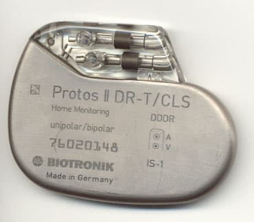
PG6CYLOS
Nov 21, 2005Cylos DR-T
Equipment Class
TNT - Licensed Non-Broadcast Transmitter Worn on Body
PG6BELOS-T
May 06, 2004Belos DR-T, Belos VR-T, and Cardiac Airbag-T
Equipment Class
TNT - Licensed Non-Broadcast Transmitter Worn on Body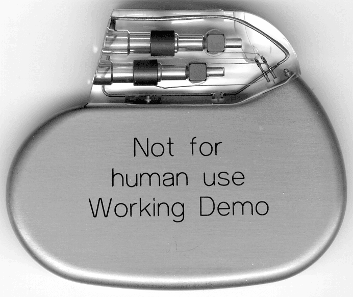
PG6BA0T
Mar 24, 2003Philos DR-T (aka Actros C-T)
Equipment Class
TNT - Licensed Non-Broadcast Transmitter Worn on Body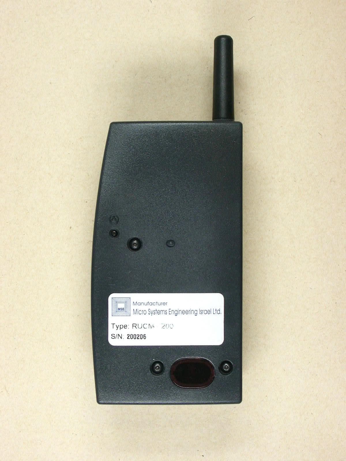
PG6RUCM200
Dec 17, 2002Patient Device
Equipment Class
PCT - PCS Licensed Transmitter worn on body