PG6CYLOSCylos DR-T
Biotronik, Inc.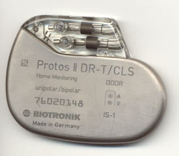
Click to zoom
Application Details
- Equipment Class
- TNT - Licensed Non-Broadcast Transmitter Worn on Body
- Date of Grant
- Nov 21, 2005
- Application Purpose
- Original Equipment
- Date of Application
- Jul 19, 2005
- Equipment Note
- Cylos DR-T
- Frequency Range
- 403.60000000 - 403.60000000
- Company
- Biotronik, Inc.
- Country
- United States
Documents & Files
Document Text
Text extracted from the exhibit documents filed with the FCC. Open a document above to read the original.
Users Manual
1 Table of Contents Table of Contents..........................................................1 Introduction...................................................................8 NBG Code..................................................11 Programmer and Software...........................11 Indications and Contraindications.............................12 Indications for Closed Loop Stimulation........12 General Indications.....................................13 General Contraindications............................14 Home Monitoring........................................................16 Introduction...............................................16 Types of Implant Messages..........................18 Home Monitoring Parameters......................19 Criteria for the Use of Home Monitoring.........20 Pacing Types – Modes................................................22 Closed Loop M odes ...................................22 Rate-Adaptive Modes....................................22 Overdrive Modes..........................................23 DDD Mode..................................................23 DDI Mode...................................................26 DVI Mode....................................................27 VDD Mode..................................................27 AAI Mode, VVI Mode.....................................28 AOO M ode, VOO Mode..................................28 2 DOO Mode..................................................28 Triggered Pacing.........................................29 DDT/A Mode, DDT/V Mode...........................29 VDI Mode....................................................30 OFF Mode...................................................30 Magnet Effect..............................................30 Summary of the Functions and Timing Intervals of the Modes...............................................32 Timing Functions........................................................34 Basic Rate..................................................34 Rate Hysteresis...........................................34 Repetitive Rate Hysteresis............................35 Scan Rate Hysteresis...................................36 Night Program............................................38 Refractory Period.........................................39 Dynamic AV Delay........................................40 AV Hysteresis.............................................41 AV Repetitive Hysteresis...............................42 AV Scan Hysteresis......................................42 Negative AV Hysteresis.................................43 Sense Compensation....................................44 Blanking Period...........................................44 Safety AV Delay...........................................45 Pacing When Exposed to Interference.............46 Pacing and Sensing Functions...................................49 Pulse Amplitude and Pulse Width..................49 Sensitivity...................................................49 3 Lead Configuration......................................50 Continuous Measurement and Recording of Lead Impedance..................................................50 Automatic Lead Check.................................51 Amplitude Control (ACC)...............................52 ACC Status.................................................57 Lead Detection and Auto-Initialization............58 Antitachycardia Functions..........................................63 Upper Tracking Rate....................................63 Tachycardia Mode.......................................64 Tachycardia Behavior...................................66 2:1 Lock-in Management..............................69 PMT Management.......................................71 Preventive Overdrive Pacing..........................74 VES Lock-in Protection.................................77 Rate Adaptation..........................................................78 Accelerometer-Based Rate Adaptation ......78 Physiologic Rate Adaptation (The CLS Feature) ....................................................79 Individually Adjusting CLS Parameters.....81 The CLS Safety Feature .............................82 Automatic Initialization of Closed Loop Stimulation...............................................82 Sensor Gain................................................83 Automatic Sensor Gain.................................84 Sensor Threshold.........................................85 Rate Increase..............................................86 4 Maximum Activity Rate.................................87 Rate Decrease.............................................87 Sensor Simulation.......................................88 Rate Fading – Rate Smoothing......................89 IEGM Recordings.........................................................92 Types of IEGM Recordings............................93 Diagnostic Memory Functions (Statistics)................96 Overview.....................................................96 Interrogating and/or Starting Statistics..........97 Timing Statistics.........................................98 Arrhythmia Statistics.................................101 Sensor Statistics.......................................107 Sensing Statistics......................................108 Pacing Statistics........................................109 Follow-up Options.....................................................111 Realtime IEGM Transmission with Markers...111 IEGM Recordings.......................................112 Analog Telemetry of Battery, Pulse and Lead Data.........................................................113 Rate and Sensor Trend...............................114 High-Resolution Threshold Test...................114 P/R-Wave Test..........................................115 Retrograde Conduction Test........................115 External Pulse Control (NIPS)......................115 Temporary Program Activatio…
Text truncated - open the document above for the full version.
Cover Letter(s)
NORTHWEST EMC, INC. 22975 NW Evergreen Parkway, Suite 400 Hillsboro, OR 97124 July 10, 2005 Dear Application Examiner: On behalf of Biotronik Inc., Northwest EMC, Inc. is submitting this application for the certification of Biotronik’s Cylos DR-T, FCC ID: PG6CYLOS. The Cylos DR-T is an implantable dual-chamber pacemaker that has separate atrial and ventricular leads and is suited for patients who need AV-synchronous pacing. It uses Biotronik’s proprietary Home Monitoring technology. Certification is sought under FCC Part 95 MICS. In the exhibits submitted for this filing, all references to Dotsero II, Cylos, Cylos DR-T, and Protos II refer to the same product. The names are interchangeable in technical reports and documents. Your efforts in reviewing this application are greatly appreciated. Best regards, Greg Kiemel, Director of Engineering Northwest EMC, Inc.
External Photos
External Photograph / Front Side External Photograph / Front Side
ID Label/Location Info
FCC ID Labeling Scheme Per 47 CFR 2.926 (e), “Where it is shown that a permanently affixed nameplate is not desirable or is not feasible, an alternative method of positively identifying the equipment may be used if approved by the Commission. The proposed alternative method of identification and the justification for its use must be included with the application for equipment authorization. Note: As an example, a device intended to be implanted within the body of a test animal or person would probably require an alternate method of identification.” Since the EUT is implanted in the human body, the FCC ID will not be applied to outside of the device. Instead, the applicant is proposing the following alternate method of applying the FCC ID number to two locations: 1.The FCC ID, along with the disclosure statement required by 95.1215(a), is in the User Manual (page 165 – see excerpt below). 2.The FCC ID also appears on the package label (see below), which is affixed to outside of the shipping box for the EUT. CYLOS DRT DUAL CHAMBER, Order No.: *** *** RATE ADAPTIVE PACEMAKER Serial No.: ******** IS-1, UNI/BIPOLAR Use Before: **/**/**** ISO 5841-3:1992(E) Rate: 60 ppm DDDR Uncoated Pulse: (A) 3.6 V; 0.4 ms (V) 3.6 V; 0.4 ms Description: One dual chamber pacemaker (two IS-1 Receptacles) with rate adaptive pacing provided by Closed Loop Stimulation (CLS) or a motion sensor. NOTE: This unit is designed for use with two (2) Unipolar or Bipolar IS-1 leads meeting the International Standard ISO 5841-3:1992(E). Mode DDD* Lower Rate 60 ppm Home Monitoring OFF Hysteresis OFF Upper Tracking Rate 130 ppm Dynamic AV Delay LOW Safety AV Delay 100 ms Ventricular Blanking Period 10 ms Magnet Rate Auto Pulse Amplitude (A) 3.6 V; (V) 3.6 V Pulse Width (A) 0.4 ms; (V) 0.4 ms Sensitivity (A) 1.0 mV; (V) 2.5 mV Refractory Period (A) 425 ms; (V) 250 ms Polarity Sense Unipolar Polarity Pace Unipolar *See enclosed Technical Manual for programmable values. STERILE: Pacemaker as identified and accessories NON-STERILE: Package Inserts STERILIZATION: This unit has been gas sterilized with ethylene oxide. Sterility cannot be guaranteed if the package has been damaged during transportation. Please examine the package carefully before opening. If it shows any evidence of damage or mishandling, it should be returned immediately to BIOTRONIK. Once the box seal has been broken, title passes to the hospital and a purchase order is required. CAUTION: Because of the numerous available 3.2 mm configurations, e.g., the IS-1 and the VS-1 standards, lead/pulse generator compatibility should be confirmed with the pulse generator and/or lead manufacturer prior to the implantation of a pacing system. CAUTION: Recommended Storage Temperature: 5° C - 55° C (41° F - 131° F). CAUTION: Federal (U.S.A.) law restricts this device to sale by, or on the order of, a physician. FCC Statement: (FCC I.D# PG6CYLOS) CYLOS DR-T is equipped with an RF transmitter for wireless communications. This device must not interfere with stations operating in the 400.150 - 406.000 MHz band in the Meteorological Satellite or Earth Exploration Satellite Services and must accept any interference received, including interference that may cause undesired operation. Made in Germany TBD Manufactured by: Distributed by: BIOTRONIK GmbH & Co. KG BIOTRONIK Inc. Woermannkehre 1 6024 Jean Road D-12359 Berlin Lake Oswego, OR 97035-5369 Germany (800)547-0395 Device / No.: CYLOS DR-T / *** *** Serial No.: * Manufacturer Name/No.: BIOTRONIK / 004 Device / No.: CYLOS DR-T / *** *** Serial No.: * Manufacturer Name/No.: BIOTRONIK / 004 Device / No.: CYLOS DR-T / *** *** Serial No.: * Manufacturer Name/No.: BIOTRONIK / 004 Device / No.: CYLOS DR-T / *** *** Serial No.: * Manufacturer Name/No.: BIOTRONIK / 004 Device / No.: CYLOS DR-T / *** *** Serial No.: * Manufacturer Name/No.: BIOTRONIK / 004 Device / No.: CYLOS DR-T / *** *** Serial No.: * Manufacturer Name/No.: BIOTRONIK / 004 Device / No.: CYLOS DR-T / *** *** Serial No.: * Manufacturer Name/No.: BIOTRONIK / 004 Device / No.: CYLOS DR-T / *** *** Serial No.: * Manufacturer Name/No.: BIOTRONIK / 004 Device / No.: CYLOS DR-T / *** *** Serial No.: * Manufacturer Name/No.: BIOTRONIK / 004 Device / No.: CYLOS DR-T / *** *** Serial No.: * Manufacturer Name/No.: BIOTRONIK / 004 1 6 5 Te c hn ic a l Da ta Fed eral Com m unications Com m is sion Dis clos ure Th e CYLOS DR-T p a c e m a ke r is eq u ip p e d wit h a n RF t ra n s m it t er fo r wir e le s s c om m u n ic a t io n s . Th is t r a ns m it t e r is a ut h or iz e d b y r u le u n d e r t h e Me d ic a l Im p la nt Com m u n ic a t io ns S e r vic e (4 7 CFR P a rt 9 5 ) a n d m us t n ot ca u s e h a rm fu l in t e r fe r e n c e t o s t a t io ns op e r a t in g in t h e 4 0 0 .1 5 0 - 4 0 6 .0 0 0 MHz b a n d in t h e Met eo r o lo g ica l Aid s (i.e ., t r a n s m it t e r s a n d r e c e ive r s u s e d t o com m u n ic a t e we a t h e r d a t a ), t h e Me t e or o lo g ica l S a t e llit e , o r t h e Ea rt h Exp lo r a t io n S a t e llit e S e rvic e s a n d m us t a cc e p t int e r fe r e n c e t h a t m a y b e c a u s e d b y s u ch a id s , in c lu d in g in t e r fe r e n c e t h a t m a y c a us e u n d e s ir e d o p e r a t io n . Th is t r a n s m it t e r s h a ll b e u s e d o n ly in a c c o r d a n c e wit h t h e FCC Ru le s g o ve r n in g t h e Me d ic a l Im p la nt Com m u n ic a t io n s S e r vic e . An a log a n d d ig it a l vo ic e c om m u n ic a t io n s a r e p ro h ib it e d . Alt h o u gh t h is t r a ns m it t e r h a s b e e n a p p r o ve d b y t h e Fe d e r a l Com m u n ic a t io n s Com m is s io n , t h e r e is n o g u a r a nt e e t h a t it will n ot r e c e ive int e r fe r e n c e o r t h a t a n y p a rt ic u la r t r a n s m is s io n fr om t h is t ra n s m it t er will b e fr e e fr o m int e r fe r e n c e . Th e FCC ID n um b e r fo r t h is d e vic e is : P G6 CYLOS .
Parts List/Tune Up Info
Tune-up Procedure “Describe the Tune-up procedure over the power range, or at specific operating power levels.” There are no tunable elements in the transmitter and no tune up procedure.
RF Exposure Info
SAR Analysis of Cylos DR-T (PG6CYLOS) By Similarity to Philos DR-T (PG6BAOT) Certification of medical-implant transmitters under FCC Part 95 Medical Implant Communication Service (MICS) requires a measurement or Finite Difference Time Domain (FDTD) analysis of the Specific Absorption Rate (SAR) associated with the presence of a non-ionizing, radio frequency (RF) transmitters in a human body. Biotronik, a manufacturer of Pacemaker and Defibrillator implant devices employing ultra low-power RF transmitters, has performed FDTD SAR analysis on numerous products that have been approved by the FCC and are currently in production. These implants comply with the FCC Part 95 MICS specified SAR limits with a margin of 25.5 dB. That is, Biotronik’s currently approved medical implants generate SAR levels of 4.54 mW/kg, only 0.28% of the maximum acceptable level permitted by the FCC (1.6 W/kg). By their very nature, battery-powered implants, must operate at very low power levels to achieve a battery service life of 5 to 7 years in a patient, and hence the resulting SAR levels are inherently very low. This is very different than typical cellular telephone electronics which transmit signals at SAR levels more than 350 times higher than the 4.54 mW/kg level of currently approved Biotronik medical implants. Since the ultra low-power RF transmitters employed in Biotronik’s implants produce SAR levels significantly lower than the maximum acceptable level, Biotronik submits this SAR analysis for the Cylos DR-T pacemaker (FCC ID: PG6CYLOS) based upon its similarity to a currently approved product, Philos DR-T (FCC ID: PG6BAOT). The PG6CYLOS RF transmitter is similar to the PG6BAOT RF transmitter that was granted FCC approval, and complies with the SAR limits with a margin of 25.5 dB. Biotronik submits the following exhibits to demonstrate compliance with the Specific Absorption Rate (SAR) limits as part of the FCC Part 95 submission for the Cylos DR-T Pacemaker (FCC ID: PG6CYLOS). Exhibit (S1) - Similarity of RF Transmitter Circuits Exhibit (S2) - Similarity of RF Transmitter Antenna and Housing Design Exhibit (S3) - Similarity of Production Acceptance Test Specification Exhibit (S4) - Similarity of Measured Radiated Emissions Exhibit (S5) – SAR Analysis of Philos (FCC ID# PG6BAOT) Exhibit (S1) - Similarity of RF Transmitter Circuits Figure (S1) in Exhibit K – Schematics, shows the RF transmitter circuitry of the Cylos (PG6CYLOS) and Philos (PG6BAOT) pacemakers. Both pacemakers utilize a single transistor SAW-stabilized Colpitts oscillator (Q801 in PG6CYLOS, and Q101 in PG6BAOT). Both pacemakers also use a single transistor buffer amplifier stage (Q802 in PG6CYLOS, and Q102 in PG6BAOT) to couple the oscillator signal to the antenna. The transistors used in PG6CYLOS are equivalent replacements for the transistors used in PG6BAOT, which are now obsolete. The transistors in PG6CYLOS are biased with slightly more collector current than those in PG6BAOT. This results in a slight increase in output power in PG6CYLOS, but as shown in Exhibit (S3) and Exhibit (S4), the power is significantly below the acceptable 47 CFR 95.639 (f) (1)-(2) limits. PG6CYLOS also incorporates a low pass filter (L803 and C812) at the output of the buffer amplifier thereby ensuring emissions at the harmonics of the fundamental are further attenuated. Exhibit (S2) - Similarity of RF Transmitter Antenna and Housing Design As shown in Figure 2. Photograph of Philos (PG6BAOT) and Cylos (PG6CYLOS) pacemakers, the PG6CYLOS pacemaker’s housing and antenna design are similar to the PG6BAOT pacemaker. Both pacemakers utilize the same construction materials: a welded titanium case, and an epoxy header for the transmit antenna and pacemaker lead sockets. The housing of the Cylos pacemaker is approximately 0.5 cm wider to accommodate a larger circuit board assembly. Note that the Philos (PG6BAOT) pacemaker passed FCC SAR limits with 25.5 dB of margin. Increasing the housing dimension will not impact the SAR margin. Figure 2. Photograph of Philos (PG6BAOT) and Cylos (PG6CYLOS) Pacemakers Exhibit (S3) - Similarity of Production Acceptance Test Specification As shown in Table (S3) in Exhibit N - Acceptance Test Specification, the Cylos (PG6CYLOS) and Philos (PG6BAOT) implants have similar RF output power level limits. The RF output power level is measured on every production unit to ensure compliance with this specification. Although the High Limit for PG6CLYOS is 6 dB above the limit for PG6BAOT, PG6BOAT’s 25.5 dB of SAR margin ensures that PG6CYLOS will never exceed the SAR limit stipulated by the FCC. PG6CYLOS will comply with FCC SAR limits with a worst-case margin of 19.5 dB. Exhibit (S4) - Similarity of Measured Radiated Emissions As further evidence that the ultra low-power RF transmitter in Cylos (PG6CYLOS) complies with FCC SAR limits with ample margin, note the measured level of the Radiated Emissions shown in Table (S4) below. PG6CYLOS exhibits radiated emission levels substantially less (-36.7 dB) than the Field Strength of the Fundamental limits stipulated in 47 CFR 95.639 (f) (1)-(2). This data supports Exhibit (S3) - Similarity of Production Acceptance Test Specification, in that the RF transmit power limit of PG6CYLOS, which is 6 dB above PG6BAOT, can result in approximately 6 dB of additional radiated power. Although the 6 dB increase in radiated power will increase the power absorbed by the body, the net absorption is 19.5 dB less than the FCC SAR limits. This, combined with the 36.7 dB of margin in the radiated emissions level provides assurance that PG6CYLOS complies with the FCC SAR limits. Table (S4) Comparison of PG6BAOT and PG6CYLOS Radiated Emissions Frequency (MHz) Measured Field Strength (dBuV/m) 47 CFR 95.639 (f) (1) – (2) Spec. Limit (dBuV/m) Measured Level Compared to Spec. (dB) PG6CYLOS Note (1) 403.617 48.5 85.2 -36.7 PG6BAOT Note (2) 403.572 42.1 85.2 -43.1 Note (1): Measured by NW EMC, Inc., 22975 NW Evergreen Pkwy., #4…
Text truncated - open the document above for the full version.
RF Exposure Info
Response to Issues Raised by the FCC Regarding the Computational SAR Report for PG6CYLOS As highlighted in our initial submission, the Biotronik Cylos DR-T pacemaker (FCC ID: PG6CYLOS) is essentially similar to the Biotronik Philos DR-T pacemaker (FCC ID: PG6BA0T), whose SAR analysis was accepted by the FCC on March 25, 2003. The Philos DR-T pacemaker complies with the SAR limit of 1.6 W/kg with a margin of 25.5 dB. To support our claim that the Cylos DR-T pacemaker, which is essentially similar to the Philos DR-T pacemaker, also complies with the SAR Limits of 1.6 W/kg, please refer to the additional data and information provided below. Issue (1): Transmitter and Model Validations The Philos DR-T pacemaker (FCC ID: PG6BA0T) SAR analysis is on file with the FCC, and a summary of its SAR analysis is stated below: (a) SAR computation software: Remcom XFDTD Ver. 5.1.0.5 Bio-Pro, Calc FDTD 5.1, Remesher Ver. 5.1 (b) SAR analysis mesh size: 2mm 3 (c) Region of SAR analysis: Human torso, Remcom HIFI body model (d) Pacemaker model location: typical location in upper chest (e) Pacemaker physical model: includes titanium can, loop antenna, epoxy antenna header, pacing leads. (f) Pacemaker transmitter characteristics: Output power measured with a calibrated HP8595E RF spectrum analyzer, output impedance measured with a calibrated HP8753ES RF network analyzer. Modeled with Eagleware Superstar Pro Ver. 6.5b and MicroSim PSPICE Ver. 8.0 simulation software. (g) SAR analysis results: Maximum SAR: 4.54 mW/kg Maximum 1g averaged SAR 1.11 mW/kg Average SAR 427 nW/kg SAR margin between maximum SAR and ANSI/IEEE spec. limit: 25.5 dB SAR expressed as a percent of ANSII/IEEE spec. limit: 0.28% As outlined in Exhibit S – SAR Analysis, the Cylos DR-T pacemaker (FCC ID: PG6CYLOS) is essentially similar to the Philos DR-T pacemaker (FCC ID: PG6BA0T) with respect to the following areas: (a) RF transmitter circuitry (b) RF transmitter antenna and housing (c) Acceptance Test Procedure/Specification (d) Measured Radiated Emissions Levels Based upon the relative similarity of the pacemakers, and the very low SAR levels computed for the Philos DR-T pacemaker, the Cylos DR-T pacemaker would be in compliance with the ANSII/IEEE SAR limits. Issue (2): Antenna-terminal Measured Conducted Output Power and Related Testing Details The RF output power measured at the Cylos DR-T implant antenna terminals (output of the RF amplifier) was -8.04 dBm at 403.623 MHz. The measurement was made on July 1, 2005 with an HP8595E spectrum analyzer (calibrated on May 11, 2005 with a one year calibration cycle) with the following instrument settings: • Ref Level: 0 dBm • Center Frequency: 403.623 MHz (same as device transmit frequency) • Span: 200 kHz • RF Atten: 10 dB • Resolution BW: 3 kHz • Video BW: 3 kHz • Sweep Time: 100ms For the spectrum analyzer settings shown above, the RF power measurement error was verified to be less than +/- 0.2 dB. The RF power measurement accuracy was verified by comparing the spectrum analyzer measurement against a calibrated RF power meter and signal source. Additional Information: Transmitter Duty Cycle Factor The Cylos DR-T transmitter does not transmit RF energy continuously. By design, the transmitter will normally transmit 7 times daily, at the power level noted above, for a duration of approximately 80 milliseconds. Thus the implant will transmit for a total duration of approximately 0.56 seconds per day. This gives a daily transmission duty cycle of 0.00065%. Under extraordinary conditions (when there is a device failure or extraordinary medical event), the Cylos DR-T will transmit up to 24 additional times per day, for a total of 31 messages. Thus it will transmit for 2.48 seconds per day at the above noted power level. This corresponds to a daily transmission duty cycle of 0.0029%. These low duty cycle factors were not included in the above SAR analysis (which assumed continuous steady- state RF transmission – a scenario not possible in pacemaker). Considering the extremely low RF transmitter duty cycle, the already low SAR levels will be reduced by an additional factor of 0.0000065 or -51.9 dB ( 0.000029 or -45.4 dB for a device failure or extraordinary medical event) if duty cycle averaging is taken into account. Brian Sutton Biotronik September 8, 2005
Test Report
BIOTRONIK, Inc. Cylos DR-T June 14, 2005 Report No. BIOT0009 Report Prepared By www.nwemc.com 1-888-EMI-CERT © 2005 Northwest EMC, Inc 22975 NW Evergreen Parkway Suite 400 Hillsboro, Oregon 97124 Certificate of Test Issue Date: June 14, 2005 BIOTRONIK, Inc. Model: Cylos DR-T Emissions Specification Test Method Pass Fail FCC 95.639(f)(1) Field Strength of Fundamental:2004 TIA/EIA-603:1998 FCC 95.635(d) Field Strength of Radiated Emission:2004 TIA/EIA-603:1998 & ANSI C63.4:2004 FCC 95.633(e)(1) Occupied Bandwidth:2004 95.633(e)(3) & ANSI C63.4:2004 FCC 95.635(d)(4-5) Emission Mask:2004 95.635(d)(4-5) & ANSI C63.4:2004 FCC 95.628(e)(1) & 2.1055 Frequency Stability:2004 TIA/EIA-603:1993 Modifications made to the product See the Modifications section of this report Test Facility The measurement facility used to collect the data is located at: Northwest EMC, Inc. 22975 NW Evergreen Parkway, Suite 400; Hillsboro, OR 97124 Phone: (503) 844-4066 Fax: 844-3826 This site has been fully described in a report filed with and accepted by the FCC (Federal Communications Commission) and Industry Canada. Approved By: David M. Tolman, QA Manager This report must not be used to claim product certification, approval, or endorsement by NVLAP, NIST, or any agency of the federal government of the United States of America. Product compliance is the responsibility of the client, therefore the tests and equipment modes of operation represented in this report were agreed upon by the client, prior to testing. This Report may only be duplicated in its entirety. The results of this test pertain only to the sample(s) tested, the specific description is noted in each of the individual sections of the test report supporting this certificate of test. Northwest EMC Revision History Revision 05/05/03 Revision Number Description Date Page Number 00 None Northwest EMC Accreditations and Authorizations Revision 03/18/05 FCC: Accredited by NVLAP for performance of FCC radio, digital, and ISM device testing. Our Open Area Test Sites, certification chambers, and conducted measurement facilities have been fully described in reports filed with the FCC and accepted by the FCC in letters maintained in our files. Northwest EMC has been accredited by ANSI to ISO / IEC Guide 65 as a product certifier. We have been designated by the FCC as a Telecommunications Certification Body (TCB). This allows Northwest EMC to certify transmitters to FCC specifications in accordance with 47 CFR 2.960 and 2.962. NVLAP: Northwest EMC, Inc. is recognized under the United States Department of Commerce, National Institute of Standards and Technology, and National Voluntary Laboratory Accreditation Program for satisfactory compliance with the requirements of ISO/IEC 17025 for Testing Laboratories. The NVLAP accreditation encompasses Electromagnetic Compatibility Testing in accordance with the European Union EMC Directive 89/336/EEC, ANSI C63.4, MIL- STD 461E, DO-160D and SAE J1113. Additionally, Northwest EMC is accredited by NVLAP to perform radio testing in accordance with the European Union R&TTE Directive 1999/5/EEC, the requirements of FCC, and the RSS radio standards for Industry Canada. 200629-0 200630-0 200676-0 Industry Canada: Accredited by NVLAP for performance of Industry Canada RSS and ICES testing. Our Open Area Test Sites and certification chambers comply with RSS 212, Issue 1 (Provisional) and have been filed with Industry Canada and accepted. Northwest EMC has been accredited by ANSI to ISO / IEC Guide 65 as a product certifier. We have been designated by NIST and recognized by Industry Canada as a Certification Body (CB) per the APEC Mutual Recognition Arrangement (MRA). This allows Northwest EMC to certify transmitters to Industry Canada technical requirements. CAB: Designated by NIST and validated by the European Commission as a Conformity Assessment Body (CAB) to conduct tests and approve products to the EMC directive and transmitters to the R&TTE directive, as described in the U.S. - EU Mutual Recognition Agreement. TÜV Product Service: Included in TUV Product Service Group's Listing of Recognized Laboratories. It qualifies in connection with the TUV Certification after Recognition of Agent's Testing Program for the product categories and/or standards shown in TUV's current Listing of CARAT Laboratories, available from TUV. A certificate was issued to represent that this laboratory continues to meet TUV's CARAT Program requirements. Certificate No. USA0401C. TÜV Rheinland: Authorized to carryout EMC tests by order and under supervision of TÜV Rheinland. This authorization is based on "Conditions for EMC-Subcontractors" of November 1992. Northwest EMC Accreditations and Authorizations Revision 03/18/05 NEMKO: Assessed and accredited by NEMKO (Norwegian testing and certification body) for European emissions and immunity testing. As a result of NEMKO's laboratory assessment, they will accept test results from Northwest EMC, Inc. for product certification (Authorization No. ELA 119). Technology International: Assessed in accordance with ISO Guide 25 defining the general international requirements for the competence of calibration and testing laboratories and with ITI assessment criteria LACO196. Based upon that assessment, Interference Technology International, Ltd., has granted approval for specifications implementing the EU Directive on EMC (89/336/EEC and amendments). The scope of the approval was provided on a Schedule of Assessment supplied with the certificate and is available upon request. Australia/New Zealand: The National Association of Testing Authorities (NATA), Australia has been appointed by the ACA as an accreditation body to accredit test laboratories and competent bodies for EMC standards. Accredited test reports or assessments by competent bodies must carry the NATA logo. Test reports made by an overseas laboratory that has been accredited for the relevant standards by an overseas accreditation body that has a Mutual Rec…
Text truncated - open the document above for the full version.
Contact Information
Applicant
Mark Johnson(New Business Development Manager)
Test Firm
Northwest EMC, Inc.Greg Kiemel
Technical Specifications
| # | Rule Parts | Frequency Range | Power Output | Emission | Tolerance |
|---|---|---|---|---|---|
| 1 | 95I | 403.6 MHz - 403.6 MHz | 0.00 µW | 46K0F1D | 9.0000000000 ppm |
Other Applications from Biotronik, Inc.

PG6BELOS-T
May 06, 2004Belos DR-T, Belos VR-T, and Cardiac Airbag-T
Equipment Class
TNT - Licensed Non-Broadcast Transmitter Worn on Body
PG6LEXOS-T
Dec 21, 2003Lexos DR-T & Lexos VR-T
Equipment Class
TNT - Licensed Non-Broadcast Transmitter Worn on Body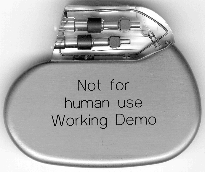
PG6BA0T
Mar 24, 2003Philos DR-T (aka Actros C-T)
Equipment Class
TNT - Licensed Non-Broadcast Transmitter Worn on Body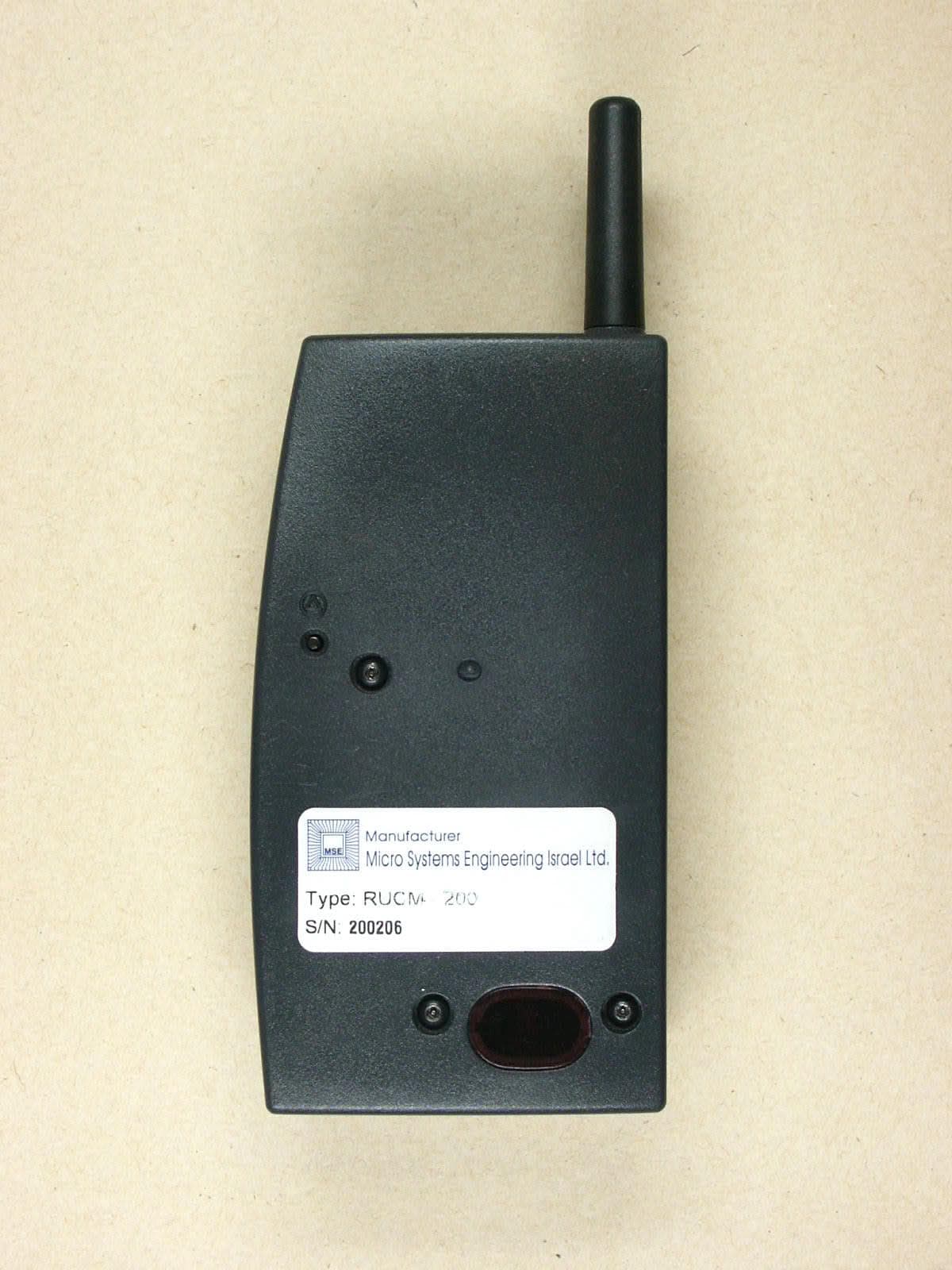
PG6RUCM200
Dec 17, 2002Patient Device
Equipment Class
PCT - PCS Licensed Transmitter worn on body