PH3DJ-FX45FRS UHF FM HANDHELD TRANSCIVER
Alinco Incorporated, Electronics Division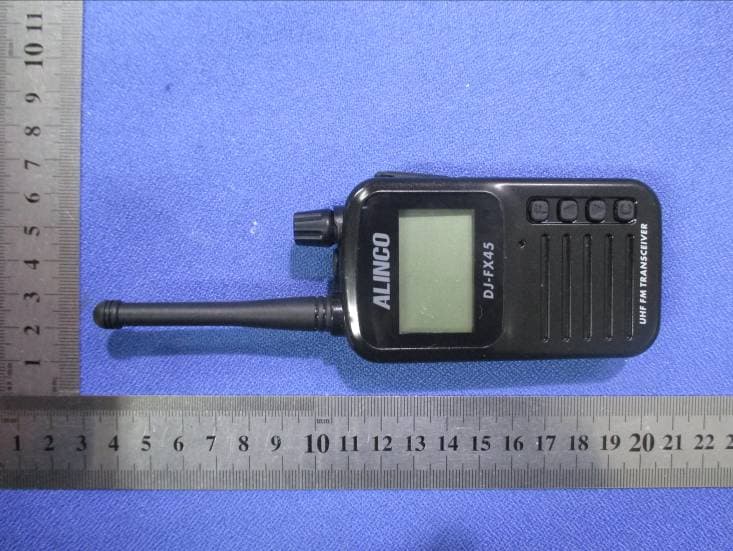
Click to zoom
Application Details
- Equipment Class
- FRF - Part 95 Family Radio Face Held Transmitter
- Date of Grant
- Mar 18, 2015
- Application Purpose
- Original Equipment
- Date of Application
- Mar 18, 2015
- Equipment Note
- FRS UHF FM HANDHELD TRANSCIVER
- Frequency Range
- 467.56250000 - 467.71250000
- Country
- Japan
Documents & Files
Document Text
Text extracted from the exhibit documents filed with the FCC. Open a document above to read the original.
Users Manual
Instruction Manual Thank you for purchasing your new Alinco transceiver. This instruction manual contains important safety and operating instructions. Please read this manual carefully before using the product and keep it for future reference. Introduction Introduction Please be informed that this manual has been edited with dealer-use in mind. The product is delivered toconsumersafter being programmed by dealers. The product is blocked and not functional in ex-factory statedue to regulations. Please read this manual completely from the first page to the last, to learn all the functions theproduct offers. It is important to note that some of the operations may be explained in relationto information in previous chapters. By reading just one part of the manual, you may risk notunderstanding the complete explanation of the function. In addition, please understand that your radio may be programmed by the dealer according to the local regulation, masking some offeatures mentioned in this manual. Please consult your dealer for details of programming. 2 Before transmitting 3 Before transmitting There are many radio stations operating in proximity to the frequency ranges this product covers. Becareful not to cause interference when transmitting around such radio stations. ■ Lightning Any person is not safe outdoor during thunderstorm and lightning. This condition is getting worse ifsomebody keeps a hand-held radio; chances of being hit by lightning are doubled since lightning mayhit a radio antenna as well. At this time, there is no hand-held radio having any kind of protection againstlightning current (which is higher than10 kA.). Note also that no car provides adequate protection of itspassengers or drivers against lightning as well. Therefore, Alinco will not take responsibility for any dangerassociated with using its hand-held radios outdoor or inside the car during lightning. ■ Covering ranges You may expect a range of approx.3km/2 miles or more at high-power when located on a flat, noise-freeplace like on a beach. However, it may vary drastically depending on how to wear and carry the radios,surrounding locations/conditions and static noise levels (below or near power transmission lines), etc. Inurban areas with many buildings or inside a building, such covering range will become drastically shorteven to several tens of meters. NOTICE/Compliance Information Statement NOTICE/Compliance Information Statement For your safe and efficient use of the transceiver, please read the following safety information. 1.The maintenance work can be carried out only by professional and technical personnel, please do not disassemble or reassemble by yourself. 2.Can use only the specified battery and charger, rechargeable 5 to 40 °C range. 3.To avoid electromagnetic interference and other problems caused by electromagnetic incompatibility, please close the transceiver in the place where there is a sign showing "No transceiver", as well as on the plane where transceivers are required to be shut down by crew. 4.In the car with an airbag, do not put the transceiver within the reach of expansion of the airbag. 5.When entering into a flammable and explosive environment, please close the transceiver. 6.You should not get close to blasting areas and areas where deployed some detonators until the transceiver is turned off. 7.Do not use the transceiver with a damaged antenna, for the damaged antenna may cause light burn of your skin. 8.Do not expose transceivers under direct sunlight for a long time, or place it near some heating equipment. 4 Safety Training Information Your FRS radio generates RF electromagnetic energy during transmitmode. This radio is intended for use by “General Population” in uncontrolled environment. This radio has been tested and complies with the FCC RF exposurelimits for “General population.” In addition, your ALINCO radio complieswith the following NOTICE/Compliance Information Statement 5 Standards and Guidelines with regard to RF energyand electromagnetic energy levels and evaluation of such levels for exposure to humans: • FCC OET Bulletin 65 Edition 01-01 Supplement C, Evaluating Compliance with FCC Guidelines for Human Exposure to Radio Frequency Electromagnetic Fields. • American National Standards Institute (C95.1-1992), IEEE Standardfor Safety Levels with Respect to Human Exposure to Radio Frequency Electromagnetic Fields, 3 kHz to 300 GHz. •American National Standards Institute (C95.3-1992), IEEE Recommended Practice for the Measurement of Potentially HazardousElectromagnetic Fields- RF and Microwave. • The following accessories are authorized for use with this product.Use of accessories other than those specified may result in RF exposure levels exceeding the FCC requirements for wireless RF exposure.; Belt Clip(EBC-40), Rechargeable Li-ion Battery Pack (EBP-90), Earphone microphone (EME-24/EME-61)and Speaker microphone (EMS-60). To ensure that your expose to RF electromagnetic energy is withinthe FCC allowable limits for general population/uncontrolled use,always adhere to the following guidelines: •DO NOT transmit for more than 50% of total radio use time (“50% duty cycle”). Transmitting more than 50% of the time can causeFCC RF exposure compliance requirements to be exceeded. Theradio is transmitting when the “TX indicator” lights red. You cancause the radio to transmit by pressing the "PTT" switch. The information listed above provides the user with the informationneeded to make user aware of RF exposure, and what to do to assurethat this radio operates with the FCC RF exposure limits of this radio. Features Features 6 ● Computer-programmable with free software downloadable from Alinco website (with optional ERW-8 interface cable) ● Works with 3.7V 1000mAh li-ion cell yet powerful legal-limit TX output and clear, crisp 300mW Audio output ● Compact size 50W x 157H x 19D mm (with antenna) ● Weight less than 90g inclusive of 3.7V 1000mAh li-ion cell and antenna ● Scan functions ● …
Text truncated - open the document above for the full version.
Users Manual
19 Basic Operation 4.CTCSS/CDCSS CTCSS/CDCSS signaling is mainly used to avoid receiving irrelated signals on the same channel. If CTCSS/CDCSS signaling is set, it can only receive the calls of those who share the same channel and have the same CTCSS/CDCSS signaling, but if CTCSS/CDCSS signaling is not set, you will receive all the calls on the channel. Press " " key, group number flashing display; switch button select group number is determined. Note: 1.Even if to different spectrum radio emission, can't hear voice but can displays the receiving state. At this point, even if press , transceiver prompted warnings and transmitting banned. Please transmit when it not show signal receipt. 2.All of the channel can be used together after set the "Group" number. 5.VOX function With this feature, transmitting opeartion is launched by the voice you said without having to press the " " botton. It become to receive state automatically after you talk. Press " " key first, enter the function menu, and then press the " " key and " " key to select VOX function. And then press " " key into this function can be set up, and then press " " and " " key to select 1-5 sensitivity, press " " key to confirm. Select 5 grade, transceiver receive a small voice is involved. When do not use this function, please choose OF. Note: 1.In the receving, when it prompt confirmation TONE, CALL TONE, SQL OFF, and all sorts of function setting can't use this function. 2.When the battery is low, it can't use this feature. Please charge in adavance. 3.It's able to talk for 3 minutes. 20 Basic Operation 21 Basic Operation 6.DW function You can set two channels you need to receive state at the same time, no matter which channel information all can talk.After the call, you can return to the state of "DW". 2 you need to channel can be set to receive state at the same time, no matter which channel information can be fired. After the completion of the finished, can be restored to the DW. Press " " key, enter the function menu, and then press " " key and " " key selected DW function, and then press " " key into the function set. Then press " " key and " " key, choose hope to accept the channel at the same time.(1-14 channel) Finally press " " key to confirm. Note: 1.Press " " key channel and a second set of channels before can receive at the same time. 2.When using DW function, set the two channel will display. If you want to remove the DW function, into the function setting, do not choose 1-14 channel, choose "OF" key. When it in DW function, can not change the channel,. If you want to change channel, please remove the DW function first. 7.SQL function In setting the level of SQL(that is, to eliminate the noise level), generally choose 3 grade. OF state, when receiving ,it often have noise. Please do not set OF state, if you want to eliminate the noise. Press " " key, enter the function menu, and then press " " key and " " key selected SQL function, and then press " " key into function set. Press " " key confirm. 8.Secret words function Can not speak to your parter after setting the secret words. You do not want to hear others' information, or there are important conversation when using this feature will be very convenient. Press " " key, enter the function menu, and then press the " " key and " " key selected secret message function, and then press " " key into function set. Press " " key and " " key to choose ON/OF Press " " key to confirm Note: When setting the secret message function, and the other side, please use the same channel, dumb tidings. If all of the channel is not consistent, can not talk. 22 Basic Operation Note: Set the SQL function as "OF",the channel to receive all sound in "GROUP" mode. 23 Basic Operation 9.KEY TONE function Key tone can set to open or close. Press " " key, enter the function menu, then press " " key or " " key selected KEY TONE function, and then press " " key into the function set. Press " " key and " " key, selecting ON/OF Press " " key to confirm. It shows symbols, means the KEY TONE is open state 10.Roger tone function After transmitting, loosen PTT key has to be done to transmit prompt. Tell your parter the trammitting is complete. Press " " key, enter the function menu, and then press " " key or " " key selected Roger tone function, and then press " " key into the function set. Press " " key and " " key to select ON/OF Press " " key to confirm. 24 Basic Operation 12.Lock key function This feature is designed to prevent accidentally press the wrong key. Long press the " " key 3 seconds, the key symbols will be displayed, the lock key function opens. (shutdown or restart the function effectively. When this feature is open, press the PTT key and moni key button without function, and rang the prompt tone. PTT key can be used to call! Long press the " " key 3 seconds again, the key symbol will disappear, to remove this function! 11.APO function Within the scope of the set time, it will cut off power supply if you do nothing. In order to prevent forget to turn off the power and the function of the design. Press " " key, enter the function menu; then press " " key or " " key to select APO function, then press " " key into the function set. Press " " key and " " key, select 1h-6h/OF Press " " key to confirm Note:After turn off the power supply, power switch of the transceiver is in a state of "ON" when set this function. When need to open the power supply, need to open the POWER to the state of "OF", and then readjust the state of "ON". 25 Basic Operation 14.The rest capacity of batterry display function 1.When full, it have sections 3 batteries symbol which will be reduced as using. 2.Please pay attetion to using and recharging in advance. 3.Without electricity, it will show LOBR, at the same time you will be prompted warnings.After several times will be cut off power supply. 13.CALL TONE Function 1.Pressed PTT twice quickly, it will have CALL TONE syllable. you call the other party; 2.Warning ea…
Text truncated - open the document above for the full version.
Cover Letter(s)
Alinco Incorporated, Electronics Division Yodoyabashi Dai Building 13F, 4-4-9 Koraibashi, Chuo-ku, Osaka 541-0043, Japan Tel: 06-7636-2360 Fax: 06-6208-3801 DATE 03-16-2015 FCC ID: PH3DJ-FX45 Nemko Canada Inc 303 River Road Ottawa, Ontario, Canada K1V 1H2 Attn: Director of Certification Authority to Act as Agent On our behalf, I appoint Shenzhen CTL Testing Technology Co., Ltd.(MR. Tracy Qi) at Floor 1-A, Baisha Technology Park, No. 3011, Shahexi Road, Nanshan, Shenzhen 518055 China to act as our agent in the preparation of this application for equipment certification. I certify that submitted documents properly describe the device or system for which equipment certification is sought. I also certify that each unit manufactured, imported or marketed, as defined in the Federal Communications Commission’s regulations will have affixed to it a label identical to that submitted for approval with this application. For instances where our authorized agent signs the application for certification on our behalf, I acknowledge that all responsibility for complying with the terms and conditions for certification, as specified by Nemko Canada Inc, still resides with Alinco Incorporated, Electronics Division at Yodoyabashi Dai Building 13F, 4-4-9 Koraibashi, Chuo-ku, Osaka 541-0043, Japan. Dated this 03-16-2015 Agency agreement expiration date: 03-15-2016 By: Kazuhiro Kusuhara Signature Printed Title: General Manager, Production, Electronics Div. On behalf of : Alinco Incorporated, Electronics Division Telephone: 06-7636-2360
Cover Letter(s)
Alinco Incorporated, Electronics Division Yodoyabashi Dai Building 13F, 4-4-9 Koraibashi, Chuo-ku, Osaka 541-0043, Japan Tel: 06-7636-2360 Fax: 06-6208-3801 DATE 03-16-2015 Equipment Autorisation Division Federal Communications Commission 7435 Oakland Mills Road Columbia, MD 21046 FCC ID: PH3DJ-FX45 Product Name: FRS UHF FM HANDHELD TRANSCIVER Request for Confidentiality Pursuant to Sections 0.457 and 0.459 of the commissions rules, we hereby request that the following documents be held confidential: (List here the documents for which you are seeking confidentiality – for example ...) •Schematics •Block diagram •Operation description •Tune up Procedure These materials contain trade secrets and proprietary information and are not customarily released to the public. The public disclosure of this information might be harmful to the company and provide unjustified benefits to our competitors. Dated this 03-16-2015 By: Kazuh iro Kusuhara Sig naturePrin ted T itle: General Manager, Production, Electronics Div. On behalf of : Alinco Incorporated, Electronics Division Tel ephone: 06-7636-2360
Cover Letter(s)
Alinco Incorporated, Electronics Division Yodoyabashi Dai Building 13F, 4-4-9 Koraibashi, Chuo-ku, Osaka 541-0043, Japan Tel: 06-7636-2360 Fax: 06-6208-3801 Letter for Label Proposal FCC ID: PH3DJ-FX45 Mar. 18, 2015 Equipment Authorization Division Office of Engineering and Technology Federal Communications Commission 7435 Oakland Mills Road Columbia, MD 21046 Dear Sirs: Alinco Incorporated, Electronics Division requests acceptance of the labeling proposal described below for transceivers bearing FCC identifier PH3DJ-FX45. The subject transceivers are compact handheld models as shown in figure 1, authorized under 47CFR Part 95 for PERSONAL RADIO SERVICES. Figure 1. Because the majority of the transceiver housing is composed of display, speaker, operating controls, and a removable battery pack, there is extremely limited space available to attach the required label carrying the FCC identifier. Attaching the label to the battery pack is not acceptable because the battery pack is a removable item. For this reason, Alinco Incorporated, Electronics Division proposes placing the label carrying the FCC identifier inside the battery compartment as shown in figure 2. Alinco Incorporated, Electronics Division Yodoyabashi Dai Building 13F, 4-4-9 Koraibashi, Chuo-ku, Osaka 541-0043, Japan Tel: 06-7636-2360 Fax: 06-6208-3801 Proposed Label Location on EUT Figure 2. The consumer packaging for these models includes the battery pack as a separate item, NOT installed on the radio. As such, the FCC identifier will be readily visible to the user before the battery pack is installed and whenever the battery pack is removed or replaced. In this location, the label will also be protected from physical abuse and remain readable for the anticipated life of the device. The consumer packaging for these models is a "gift box" which does not allow the transceiver to be seen at time of purchase. In order to meet the requirements of 47CFR Part 2.925 (d), Alinco Incorporated, Electronics Division will add the FCC identifier "PH3DJ-FX45" to the outside of the consumer "gift box" packaging. Sincerely yours, Kazuhiro Kusuhara / General Manager, Production, Electronics Div.
External Photos
External Photos
ID Label/Location Info
Applicant: Alinco Incorporated, Electronics Division FCC ID: PH3DJ- FX45 Model Name: DJ-FX45 FRS UHF FM HANDHELD TRANSCIVER Model Name: DJ-FX45 FCC ID: PH3DJ- FX45 The FCC identifier is marked in the product label and the RF exposure caution label is attached on the rear side of the cabinet. The user notice and warning statement are described in the user manual. . Proposed Label Location on EUT
Internal Photos
Internal Photos
RF Exposure Info
Shenzhen CTL Testing Technology Co., Ltd. Tel: +86-755-89486194 Fax: +86-755-26636041 SAR TEST REPORT Report Reference No. .................... : FCC ID. ............................................ : CTL1503030536-EMF PH3DJ-FX45 Compiled by ( position+printed name+signature) .. : File administrators Happy Guo Supervised by ( position+printed name+signature) .. : Test Engineer Jacky Chen Approved by ( position+printed name+signature) .. : Manager Tracy Qi Date of issue ..................................... : Mar. 08, 2015 Testing Laboratory Name .............. : Shenzhen CTL Electromagnetic Technology Co., Ltd. Address............................................. : Floor 1-A, Baisha Technology Park, No. 3011, Shahexi Road, Nanshan, Shenzhen 518055 China. Testing Laboratory Name .............. : The Testing and Technology Center for Industrial Products of Shenzhen Entry-Exit Inspection and Quarantine Bureau Address............................................. : No.289, 8th Industry Road, NanshanDistrict,Shenzhen,Guangdong Applicant’s name ............................ : Alinco Incorporated, Electronics Division Address............................................. : Yodoyabashi Dai Building 13F, 4-4-9 Koraibashi, Chuo-ku, Osaka 541-0043, Japan Test specification .......................... : Standard ........................................... : ANSI C95.1–1999 47CFR §2.1093 TRF Originator .................................. : Shenzhen CTL Electromagnetic Technology Co., Ltd. Master TRF ....................................... : Dated 2011-01 Shenzhen CTL Electromagnetic Technology Co., Ltd. All rights reserved. This publication may be reproduced in whole or in part for non-commercial purposes as long as the Shenzhen CTL Electromagnetic Technology Co., Ltd. is acknowledged as copyright owner and source of the material. Shenzhen CTL Electromagnetic Technology Co., Ltd. takes no responsibility for and will not assume liability for damages resulting from the reader's interpretation of the reproduced material due to its placement and context. Test item description .....................: FRS UHF FM HANDHELD TRANSCIVER Trade Mark ....................................... : ALINCO Model/Type reference ....................... : DJ-FX45 Ratings.............................................. : DC 3.70V EUT Type ......................................... : Production Unit Exposure category ............................ : General population/uncontrolled environment Result ................................................ : PASS V1.0 Page 2 of 57 Report No.: CTL1503030536-EMF T E S T R E P O R T Test Report No. : CTL1503030536-EMF Mar. 08, 2015 ______________________________________________________________________________________________ Date of issue Equipment under Test : FRS UHF FM HANDHELD TRANSCIVER Model /Type : DJ-FX45 Listed Models : / Applicant : Alinco Incorporated, Electronics Division Address : Yodoyabashi Dai Building 13F, 4-4-9 Koraibashi, Chuo- ku, Osaka 541-0043, Japan Manufacturer : KONGTOP INDUSTRIAL (SHENZHEN) CO.,LTD. Address : Xinwuyuan,NO.1,Difu Road, Gushu, Xixiang, Baoan, Shenzhen, China Test Result: PASS The test report merely corresponds to the test sample. It is not permitted to copy extracts of these test result without the written permission of the test laboratory. V1.0 Page 3 of 57 Report No.: CTL1503030536-EMF ** Modifited History ** Revison Description Issued Data Remark Revsion 1.0 Initial Test Report Release 2015-03-08 Tracy Qi V1.0 Page 4 of 57 Report No.: CTL1503030536-EMF Contents 1. T E S T S T A N D A R D S 5 2. S U M M A R Y 6 2.1. General Remarks 6 2.2. Product Description 6 2.3. Summary SAR Results 6 2.4. Equipment under Test 6 2.5. EUT operation mode 6 2.6. TEST Configuration 7 2.7. EUT configuration 7 3. T E S T E N V I R O N M E N T 8 3.1. Address of the test laboratory 8 3.2. Test Facility 8 3.3. Environmental conditions 8 3.4. SAR Limits 8 3.5. Equipments Used during the Test 9 4. S A R M E A S U R E M E N T S S Y ST E M C O N F I G U R A T I O N 10 4.1. SAR Measurement Set-up 10 4.2. DASY5 E-field Probe System 11 4.3. Phantoms 11 4.4. Device Holder 12 4.5. Scanning Procedure 12 4.6. Data Storage and Evaluation 13 4.7. SAR Measurement System 14 4.8. Dielectric Performance 15 4.9. System Check 15 4.10. Measurement Procedures 16 5. T E S T C O N D I T I O N S A N D R E S U L T S 21 5.1. Conducted Power Results 21 5.2. Test reduction procedure 21 5.3. SAR Measurement Results 21 5.4. SAR Measurement Variability 21 5.5. Measurement Uncertainty (300-3GHz) 22 5.6. System Check Results 25 5.7. SAR Test Graph Results 27 6. C A L I B R A T I O N C E R T I F I CA T E 29 6.1. Probe Calibration Ceriticate 29 6.2. D450V3 Dipole Calibration Certificate 40 6.3. DAE4 Calibration Certificate 48 7. T E S T S E T U P P H O T O S 51 8. E X T E R N A L P H O T O S O F T H E E U T 53 V1.0 Page 5 of 57 Report No.: CTL1503030536-EMF 1. T E S T S T A N D A R D S The tests were performed according to following standards: IEEE 1528-2003 (2003-04): Recommended Practice for Determining the Peak Spatial-Average Specific Absorption Rate (SAR) in the Human Head from Wireless Communications Devices: Measurement Techniques: IEEE 1528-2013 (2014-06): Recommended Practice for Determining the Peak Spatial-Average Specific Absorption Rate (SAR) in the Human Head from Wireless Communications Devices: Measurement Techniques IEEE Std. C95-3 (2002): IEEE Recommended Practice for the Measurement of Potentially Hazardous Electromagnetic Fields – RF and Microwave IEEE Std. C95-1 (1992): IEEE Standard for Safety Levels with Respect to Human Exposure to Radio Frequency Electromagnetic Fields, 3 kHz to 300 GHz. IEC 62209-2 (2010): Human exposure to radio frequency fields from hand-held and bodymounted wireless communication devices. Human models, instrumentation, and procedures. Procedure to determine the specific absorption rate (SAR) for wireless communication devices used in close proximity to the human body (f…
Text truncated - open the document above for the full version.
RF Exposure Info
V1.0 Page 40 of 57 Report No.: CTL1503030536-EMF 6.2. D450V3 Dipole Calibration Certificate V1.0 Page 41 of 57 Report No.: CTL1503030536-EMF V1.0 Page 42 of 57 Report No.: CTL1503030536-EMF V1.0 Page 43 of 57 Report No.: CTL1503030536-EMF V1.0 Page 44 of 57 Report No.: CTL1503030536-EMF V1.0 Page 45 of 57 Report No.: CTL1503030536-EMF V1.0 Page 46 of 57 Report No.: CTL1503030536-EMF V1.0 Page 47 of 57 Report No.: CTL1503030536-EMF V1.0 Page 48 of 57 Report No.: CTL1503030536-EMF 6.3. DAE4 Calibration Certificate V1.0 Page 49 of 57 Report No.: CTL1503030536-EMF V1.0 Page 50 of 57 Report No.: CTL1503030536-EMF V1.0 Page 51 of 57 Report No.: CTL1503030536-EMF 7. T e s t S e t u p P h o t o s Photograph of the depth in the Head Phantom (450MHz) Photograph of the depth in the Body Phantom (450MHz) V1.0 Page 52 of 57 Report No.: CTL1503030536-EMF Face-held, the front of the EUT towards phantom (The distance was 25mm) Body-worn, the front of the EUT towards ground with A1, B2, BC2 and AA1 (The distance was 0cm) Body-worn, the front of the EUT towards ground with A1, B2, BC2 and AA2 (The distance was 0cm) V1.0 Page 53 of 57 Report No.: CTL1503030536-EMF 8. E x t e r n a l P h o t o s o f t h e E U T External Photos V1.0 Page 54 of 57 Report No.: CTL1503030536-EMF V1.0 Page 55 of 57 Report No.: CTL1503030536-EMF B1- Battery, Intrinsically Safe Li-ion Battery(1000mAh): EBP-90 BC2- Belt Clip:EBC-40 V1.0 Page 56 of 57 Report No.: CTL1503030536-EMF AA1- Earphone Microphone with VOX: EME-61 AA2- Speaker & Microphone: EMS-60 V1.0 Page 57 of 57 Report No.: CTL1503030536-EMF AA3- Earphone Microphone: EME-24 .....................End of Report.........................
Test Report
Shenzhen CTL Testing Technology Co., Ltd. Tel: +86-755-89486194 Fax: +86-755-26636041 FCC PART 95 Test Report Report Reference No. ..................... : CTL1503030536-WF Compiled by ( position+printed name+signature) .. : File administrators Jacky Chen Name of the organization performing the tests ( position+printed name+signature) .. : Test Engineer Tracy Qi Approved by ( position+printed name+signature) .. : Manager Tracy Qi Date of issue ..................................... : Mar. 12, 2015 Testing Laboratory Name .............. : Shenzhen CTL Testing Technology Co., Ltd. Address ............................................. : Floor 1-A, Baisha Technology Park, No.3011, Shahexi Road, Nanshan District, Shenzhen, China 518055 Applicant’s name ............................ : Alinco Incorporated, Electronics Division Address ............................................. : Yodoyabashi Dai Building 13F, 4-4-9 Koraibashi, Chuo-ku, Osaka 541-0043, Japan Test specification: Standard ........................................... : FCC Part 95: PERSONAL RADIO SERVICES TRF Originator .................................. : Shenzhen CTL Testing Technology Co., Ltd. Master TRF ....................................... : Dated 2011-01 Shenzhen CTL Testing Technology Co., Ltd. All rights reserved. This publication may be reproduced in whole or in part for non-commercial purposes as long as the Shenzhen CTL Testing Technology Co., Ltd. is acknowledged as copyright owner and source of the material. Shenzhen CTL Testing Technology Co., Ltd. takes no responsibility for and will not assume liability for damages resulting from the reader's interpretation of the reproduced material due to its placement and context. Test item description .................... : FRS UHF FM HANDHELD TRANSCIVER FCC ID ............................................. : PH3DJ-FX45 Trade Mark ....................................... : ALINCO Model/Type reference ....................... : DJ-FX45 Modulation..................................: FM Channel Separation ........................... 12.5KHz Power Supply..............................: DC 3.7V Rated Power..............................: 0.5W Operating Frequency Range............: 462.5625~462.7125 MHz(FRS CH1~ CH7) 467.5625~467.7125 MHz(FRS CH8~ CH14) Result ................................................ : Positive V1.0 Page 2 of 43 Report No.: CTL1503030536-WF T E S T R E P O R T Test Report No. : CTL1503030536-WF Mar. 12, 2015 ______________________________________________________________________________________________ Date of issue Equipment under Test : FRS UHF FM HANDHELD TRANSCIVER Model /Type : DJ-FX45 Applicant : Alinco Incorporated, Electronics Division Address : Yodoyabashi Dai Building 13F, 4-4-9 Koraibashi, Chuo- ku, Osaka 541-0043, Japan Manufacture : KONGTOP INDUSTRIAL (SHENZHEN) CO.,LTD. Address : Xinwuyuan, No.1, Difu Road, Gushu, Xixiang, Baoan, Shenzhen, China Test Result according to the standards on page 4: Positive The test report merely corresponds to the test sample. It is not permitted to copy extracts of these test result without the written permission of the test laboratory. V1.0 Page 3 of 43 Report No.: CTL1503030536-WF Contents 1. T E S T S T A N D A R D S 4 2. S U M M A R Y 5 2.1. General Remarks 5 2.2. Equipment Under Test 5 2.3. Short description of the Equipment under Test (EUT) 5 2.4. EUT configuration 6 2.5. Related Submittal(s) / Grant (s) 6 2.6. Modifications 6 3. T E S T E N V I R O N M E N T 7 3.1. Address of the test laboratory 7 3.2. Test Facility 7 3.3. Environmental conditions 7 3.4. Configuration of Tested System 7 3.5. Statement of the measurement uncertainty 8 3.6. Equipments Used during the Test 9 3.7. General Technical Requirements and Summary of Test Results 10 4. T E S T C O N D I T I O N S A N D R E S U L T S 11 4.1. Conducted Emissions Test 11 4.2. Maximum Transmitter Power 14 4.3. Occupied bandwidth and emission mask 16 4.4. Modulation Characteristics 19 4.5. Radiated Spurious Emission 24 4.6. Frequency Stability 33 5. T E S T S E T U P P H O T O S O F T H E E U T 36 6. E X T E R N A L A N D I N T E R N AL P H O T O S O F T H E E U T 38 V1.0 Page 4 of 43 Report No.: CTL1503030536-WF 1. T E S T S T A N D A R D S The tests were performed according to following standards: FCC Part 95: PERSONAL RADIO SERVICES TIA/EIA 603: Land Mobile FM or PM Communications Equipment Measurement and Performance Standards. 47 CFR FCC Part 15 Subpart B - Unintentional Radiators FCC Part 2: FREQUENCY ALLOCA-TIONS AND RADIO TREATY MAT-TERS; GENERAL RULES AND REG-ULATIONS V1.0 Page 5 of 43 Report No.: CTL1503030536-WF 2. S U M M A R Y 2.1. General Remarks Date of receipt of test sample : Feb. 03, 2015 Testing commenced on : Feb. 03, 2015 Testing concluded on : Mar. 12, 2015 2.2. Equipment Under Test Power supply system utilised Power supply voltage : ● 120V / 60 Hz ○ 115V / 60Hz ○ 12 V DC ○ 24 V DC ● Other (specified in blank below) DC 3.7V from battery 2.3. Short description of the Equipment under Test (EUT) The FRS UHF FM HANDHELD TRANSCIVER, Model: DJ-FX…
Text truncated - open the document above for the full version.
Contact Information
Applicant
Kazuhiro Kusuhara(General Manager, Production, Electronics Div.)
Test Firm
Shenzhen CTL Testing Technology Co., Ltd.Tracy Qi
[email protected]86-755-89486194
Technical Specifications
| # | Rule Parts | Frequency Range | Power Output | Emission | Tolerance |
|---|---|---|---|---|---|
| 2 | 95B | 467.5625 MHz - 467.7125 MHz | 466.00 mW | 11K0F3E | 57 Hz |
Other Applications from Alinco Incorporated, Electronics Division
PH3-DR-B185TMKII
Apr 15, 2026VHF FM TRANSCEIVER
Equipment Class
CSR - Scanning Receiver
PH3-DJ-W70HT
Jun 06, 2025VHF/UHF DUAL BAND FM TRANSCEIVER
Equipment Class
JAV - Other Non-Digital SDoC Devices
PH3DJ-G46T
Nov 19, 2023UHF FM TRANSCEIVER
Equipment Class
TNF - Licensed Non-Broadcast Transmitter Held to Face
PH3DR-CS25
Dec 14, 2022VHF FM TRANSCEIVER
Equipment Class
CSR - Scanning Receiver
PH3DR-MD520T
May 31, 2021DMR VHF/UHF MOBILE TRANSCEIVER
Equipment Class
CSR - Scanning Receiver