PHYOMB9400USLow Power Data Transceiver
think dig High Tech Solutions GmbH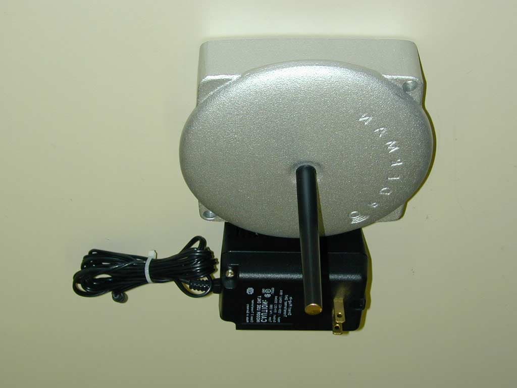
Click to zoom
Application Details
- Equipment Class
- DXT - Part 15 Low Power Transceiver, Rx Verified
- Date of Grant
- Apr 10, 2001
- Application Purpose
- Original Equipment
- Date of Application
- Apr 10, 2001
- Equipment Note
- Low Power Data Transceiver
- Frequency Range
- 902.20000000 - 905.00000000
- Country
- Austria
Documents & Files
Document Text
Text extracted from the exhibit documents filed with the FCC. Open a document above to read the original.
Users Manual
Edition 11/96 think dig High Tech Solutions Operating Manual ® ORDERMAN Your Customer Service: think dig High Tech Solutions ® ORDERMAN Edition 11/96 think dig High Tech Solutions Operating Manual ® ORDERMAN think dig High Tech Solutions ® ORDERMAN Your Customer Service: CONTENTSContents.....................................................................2General Information ...................................................3Safety Instructions .....................................................4Technical Data............................................................5Keyboard....................................................................6Display .......................................................................7Setup Menu................................................................8Setting-into-Operation .............................................12Power Supply...........................................................13Operation .................................................................15Maintenance.............................................................16Certificate of Approval..............................................17Model Plaques .........................................................17Authorization for Usage in... ................................... 18 Certificates, PlaquesPage 17 ® ORDERMAN think dig High Tech Solutions CONTENTSContents.....................................................................2General Information ...................................................3Safety Instructions .....................................................4Technical Data............................................................5Keyboard....................................................................6Display .......................................................................7Setup Menu................................................................8Setting-into-Operation .............................................12Power Supply...........................................................13Operation .................................................................15Maintenance.............................................................16Certificate of Approval..............................................17Model Plaques .........................................................17Authorization for Usage in... ................................... 18 CERTIFICATE OF APPROVALORDERMAN MODEL PLAQUESTORAGE BATTERY MODEL PLAQUE Type: OM-9401S/N: B SBMade in Austrianur mitgeliefertes Steckernetzgerät verwendenuse specified charger onlythink dig High Tech Solutions GmbH Type: OMP-9401 S/N: A12693SBNI-CD BATTERY PACK 7,2V 600mAh Use specified chargers only. Do not short-circuit. May explode if disposed of in fire funkzugelassen CEPT LPD A Germany:Austria: Contents Page 2 Certificates, PlaquesPage 17 Contents Page 2 think dig High Tech Solutions ® ORDERMAN ® ORDERMAN think dig High Tech Solutions think dig High Tech Solutions ® ORDERMAN B ZT G117521F FW ® ORDERMAN CERTIFICATE OF APPROVALORDERMAN MODEL PLAQUESTORAGE BATTERY MODEL PLAQUE Type: OM-9401S/N: B SBMade in Austrianur mitgeliefertes Steckernetzgerät verwendenuse specified charger onlythink dig High Tech Solutions GmbH Type: OMP-9401 S/N: A12693SBNI-CD BATTERY PACK 7,2V 600mAh Use specified chargers only. Do not short-circuit. May explode if disposed of in fire funkzugelassen CEPT LPD A Germany:Austria: B ZT G117521F FW ® ORDERMAN OPERATING Safety Instructions Page 4 Never hold the Orderman in the area of the integratedantenna. This could lead to range impairments.Placement on a TrayAlways place the Orderman with the storage batteryside on the tray. The Orderman is waterproof up to aheight of 10 mm.Free FallExperiments with free falling from a height of approx.1 - 1.2 meters merely left damage to the surface(cracks) of the housing.The Orderman remains functional.MaintenancePage 15 Safety Instructions Page 4 MaintenancePage 15 SAFETY INSTRUCTIONSCarefully read through this operating manual beforesetting the Orderman into operation.The Orderman is only to be run with the suppliedstorage battery and power pack.The Orderman complies with CE-guidelines and hasthe approval of the Federal Bureau for Approval inTelecommunication.WarningThe Orderman should never be exposed to rain, haleor snow fall.The Orderman is not to be disassembled. There areno parts inside the Orderman which can be servicedby a non-specialist. Contact Customer Service forrepairs. OPERATINGNever hold the Orderman in the area of the integratedantenna. This could lead to range impairments.Placement on a TrayAlways place the Orderman with the storage batteryside on the tray. The Orderman is waterproof up to aheight of 10 mm.Free FallExperiments with free falling from a height of approx.1 - 1.2 meters merely left damage to the surface(cracks) of the housing.The Orderman remains functional. SAFETY INSTRUCTIONSCarefully read through this operating manual beforesetting the Orderman into operation.The Orderman is only to be run with the suppliedstorage battery and power pack.The Orderman complies with CE-guidelines and hasthe approval of the Federal Bureau for Approval inTelecommunication.WarningThe Orderman should never be exposed to rain, haleor snow fall.The Orderman is not to be disassembled. There areno parts inside the Orderman which can be servicedby a non-specialist. Contact Customer Service forrepairs. ® ORDERMAN think dig High Tech Solutions think dig High Tech Solutions ® ORDERMAN ® ORDERMAN think dig High Tech Solutions think dig High Tech Solutions ® ORDERMAN Never touch the contacts on the Orderman - risk ofbreakage !Permanent service life - with backlight ............... approx. 2 hours, 40 min- without backlight ...................... approx. 12 hours Before the storage battery is completely discharged,the storage battery's warning symbol on the displaybegins to blink. This serves as notification that thestorage battery is to be …
Text truncated - open the document above for the full version.
Cover Letter(s)
Request for Confidentiality March 08, 2001 American Telecommunications Certification Body, Inc. 6731 Whittier Avenue Suite C110 McLean, VA 22101 RE: Certification Application FCC ID: PHYOMB9400US Please be advised that the following information is to be held confidential and behalf of THINK DIG HIGH TECH SOLUTIONS GMBH, Salzburg, Austria: • Operational/Product Description/Technical Describtion • Block Diagram • Schematics • The application contains technical information which APPLICANT NAME deems to be trade secrets and proprietary. If made public, the information might be used to the disadvantage of the applicant in the market place. Thank you for your attention to this matter. Signatory Klaus Strasser Head of R & D Department
External Photos
FCC ID PHYOMB9400US FCC ID: PHYOMB9400US External Photographs
ID Label/Location Info
FCC ID PHYOMB9400US FCC ID: PHYOMB9400US Label Information
ID Label/Location Info
FCC ID PHYOMB9400US FCC ID: PHYOMB9400US Label Location
Internal Photos
FCC ID PHYOMB9400US FCC ID: PHYOMB9400US Internal Photographs FCC ID PHYOMB9400US
Test Report
EMV-Prüfzentrum EMI/EMC-Testcenter FCC ID:PHYOMB9400USTest Report No.: 55416-10031-2 Page 1 of 55 Pages TEST-REPORT No. 50305-10056-2 Product Description Transceiver Brand Orderman Base Unit Model / Type OMB 9400 US Serial No.--- Applicant think dig High Tech Solutions GmbH Bachstrasse 59 A-5023 Salzburg Contact Klaus Strasser Order / Date January 18, 2001 Test sample received January 18, 2001 Test Specification FCC Rules Part 15, Subpart C, Section 15.249 Industry Canada RSS 210, Issue 2, Test ResultThe tested sample complies with the test specifications Tested by March 08, 2001 Johann RoidtDate Checked March 08, 2001 Johann RoidtDate Note The test data of this report relate only to the individual item which has been tested. This report shall not be reproduced except in full extent without the written approval of the testing laboratory. EMV-Prüfzentrum EMI/EMC-Testcenter FCC ID:PHYOMB9400USTest Report No.: 55416-10031-2 Page 2 of 55 Pages Table of Contents 1.Operation Mode of EUT................................................................................... 3 2.Changes made to the EUT during this certification test...................... 4 3.Configuration of EUT and periperal devices............................................ 5 4.Measuring Methods.......................................................................................... 6 Transmitter Parameter TestS (§15.209)............................................................................6 Radiated Emissions 0.009 – 30 MHz................................................................................7 Radiated Emissions 30 MHz – 1 GHz...............................................................................8 Radiated Emissions above 1 GHz....................................................................................9 Procedure for preliminary Radiated Emission Tests........................................................10 Method for comparing spectrum analyzer output to the limit............................................11 Spectrum analyzer setting for final test...........................................................................11 5.Photographs taken during testing............................................................. 12 6.List of Measurements..................................................................................... 16 7.Test Results....................................................................................................... 17 8.Equipment List................................................................................................. 21 9.Charts taken during Testing........................................................................ 23 EMV-Prüfzentrum EMI/EMC-Testcenter FCC ID:PHYOMB9400USTest Report No.: 55416-10031-2 Page 3 of 55 Pages 1. Operation Mode of EUT The EUT was equipped with a test software which allowed independent access to individual RF channels as well as transmit and receive mode. All tests were performed at lowest and highest RF-channel. EMV-Prüfzentrum EMI/EMC-Testcenter FCC ID:PHYOMB9400USTest Report No.: 55416-10031-2 Page 4 of 55 Pages 2. Changes made to the EUT during this certification test No changes have been made to the EUT during this certification test. EMV-Prüfzentrum EMI/EMC-Testcenter FCC ID:PHYOMB9400USTest Report No.: 55416-10031-2 Page 5 of 55 Pages 3. Configuration of EUT and periperal devices Configuration of cables connected to the EUT Every port of the EUT was loaded with unshielded cables Configuration of peripheral devices connected to the EUT The EUT received power from the dedicated AC adapter supplied with the unit. EMV-Prüfzentrum EMI/EMC-Testcenter FCC ID:PHYOMB9400USTest Report No.: 55416-10031-2 Page 6 of 55 Pages 4. Measuring Methods Transmitter Parameter TestS (§15.209) All transmitter parameter radiated tests are performed at a test distance of 3 meteters in a semianechoic chamber. During the tests the EUT will be rotated all around and the receiving antenna will be raised and lowered from 1 meter to 4 meter to find the maximum levels of emission. Cables and equipment will be placed and moved within the position likely to find their maximum emissions. Measurements will be made in horizontal and vertical polarization of the receiving antenna. The EUT was operating in transmit mode with its internal modulation. The bandwidth of the emission will be measured with a spectrum analyzer. Resolution Bandwidth and Video Bandwidth will be set to 10 kHz. Wooden turntable 70 cm high Test fixture with EUT Semi-anechoic chamber Test distance 3 meter Measuring antenna Spectrum analyzer EMV-Prüfzentrum EMI/EMC-Testcenter FCC ID:PHYOMB9400USTest Report No.: 55416-10031-2 Page 7 of 55 Pages Radiated Emissions 0.009 – 30 MHz Radiated emissions in the frequency range 0.009 – 30 MHz will be measured initially at a distance of 3 meters. A prescan at 3 meter distance will be performed in a shielded room with the detector of the spectrum analyzer or EMI Receiver set to peak. Final measurement is then performed at 30 meter distance. In case the regulation requires testing at other distances, the result will be extrapolated. The extrapolation factor will be determined by making a second measurement at 10 meter distance. The provisions of 15.31 (d) apply. According to section 15.209 (d) final measurementis performed with the detector set to Quasi Peak except for the frequency bands 9 – 90 kHz and 110 – 490 kHz where average detector is employed. EMV-Prüfzentrum EMI/EMC-Testcenter FCC ID:PHYOMB9400USTest Report No.: 55416-10031-2 Page 8 of 55 Pages Radiated Emissions 30 MHz – 1 GHz (FCC §15.109, RSS-210 Section 7.3) Radiated emissions in the frequency range 30 – 1000 MHz will be measured at a distance of 3 meter. The bandwidth of the spectrum analyzer will be set to 100 kHz and the detector function set to Quasi Peak. The test setup will be made in accordance with ANSI C.63.4-1992. Measurements will be made in horizontal and vertical polar…
Text truncated - open the document above for the full version.
Test Setup Photos
EMV-Prüfzentrum EMI/EMC-Testcenter FCC ID:PHYOMB9400US Test Report No.: 55416-10031-2 Page 1 of 3 Pages Conducted Emission Measurement 450 kHz – 30 MHz EMV-Prüfzentrum EMI/EMC-Testcenter FCC ID:PHYOMB9400USTest Report No.: 55416-10031-2 Page 2 of 3 Pages Radiated Emission Measurement >30 MHz - Semianechoic Chamber - EMV-Prüfzentrum EMI/EMC-Testcenter FCC ID:PHYOMB9400USTest Report No.: 55416-10031-2 Page 3 of 3 Pages Radiated Emission Measurement >30 MHz - Open Area Test Site –
Contact Information
Applicant
Christian Schlossberger(R & D Manager)
Technical Contact
Senton GmbHJohann Roidt
[email protected]+49 94 21 55 22 13
Aeussere Fruehlingstrasse 45 · Straubing · Germany
Test Firm
TUV SUD Product Service GmbH PS-EMC-STRRainer Heller
Technical Specifications
| # | Rule Parts | Frequency Range | Power Output |
|---|---|---|---|
| 1 | 15C | 902.2 MHz - 905 MHz | - |
Other Applications from think dig High Tech Solutions GmbH
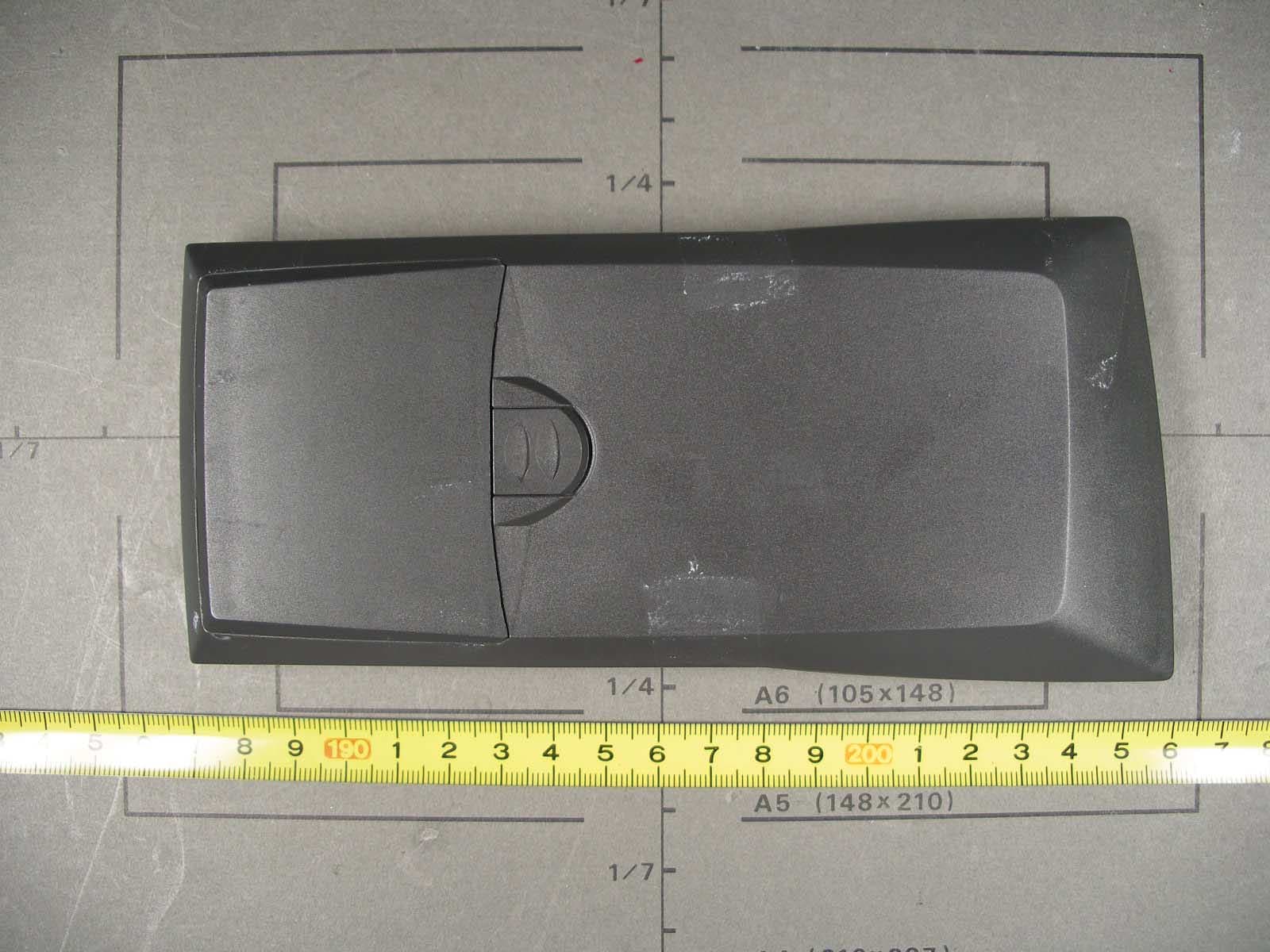
PHYMAX09151
Oct 24, 2007Mobile Terminal
Equipment Class
DXT - Part 15 Low Power Transceiver, Rx Verified
PHYOMB2-118
Apr 14, 2004Transceiver Base Unit
Equipment Class
DXT - Part 15 Low Power Transceiver, Rx Verified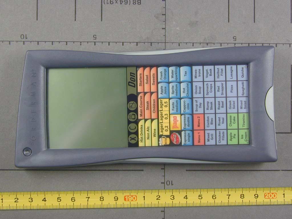
PHYOMDON
Mar 27, 2002Data Transceiver
Equipment Class
DXT - Part 15 Low Power Transceiver, Rx Verified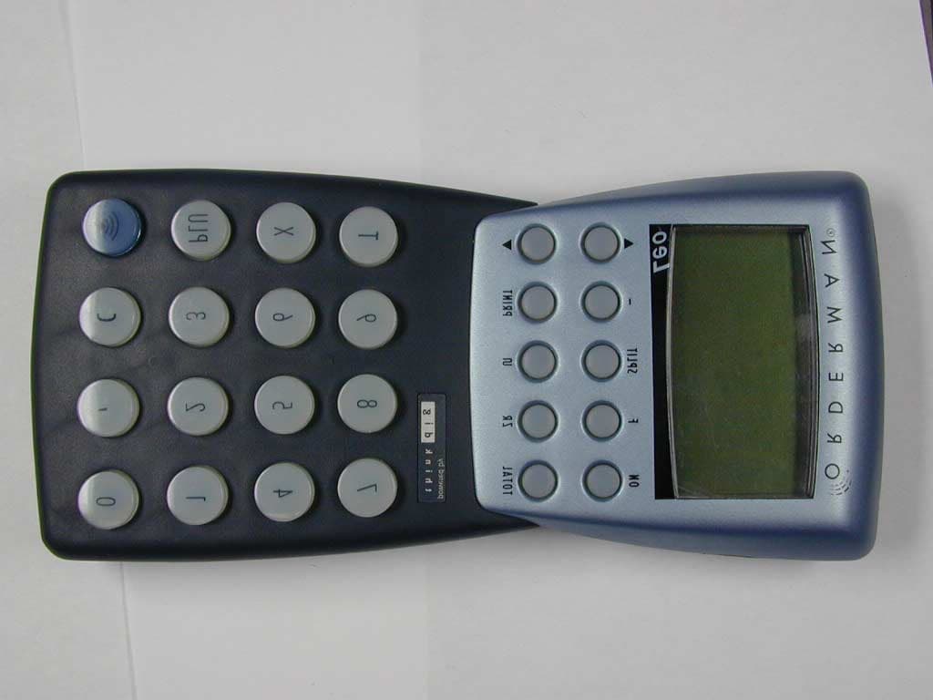
PHYOM9401US
Apr 15, 2001Data Transceiver
Equipment Class
DXT - Part 15 Low Power Transceiver, Rx Verified