PI4-TDK-BTISMBluetooth Intelligent Serial Module
Laird Connectivity, LLC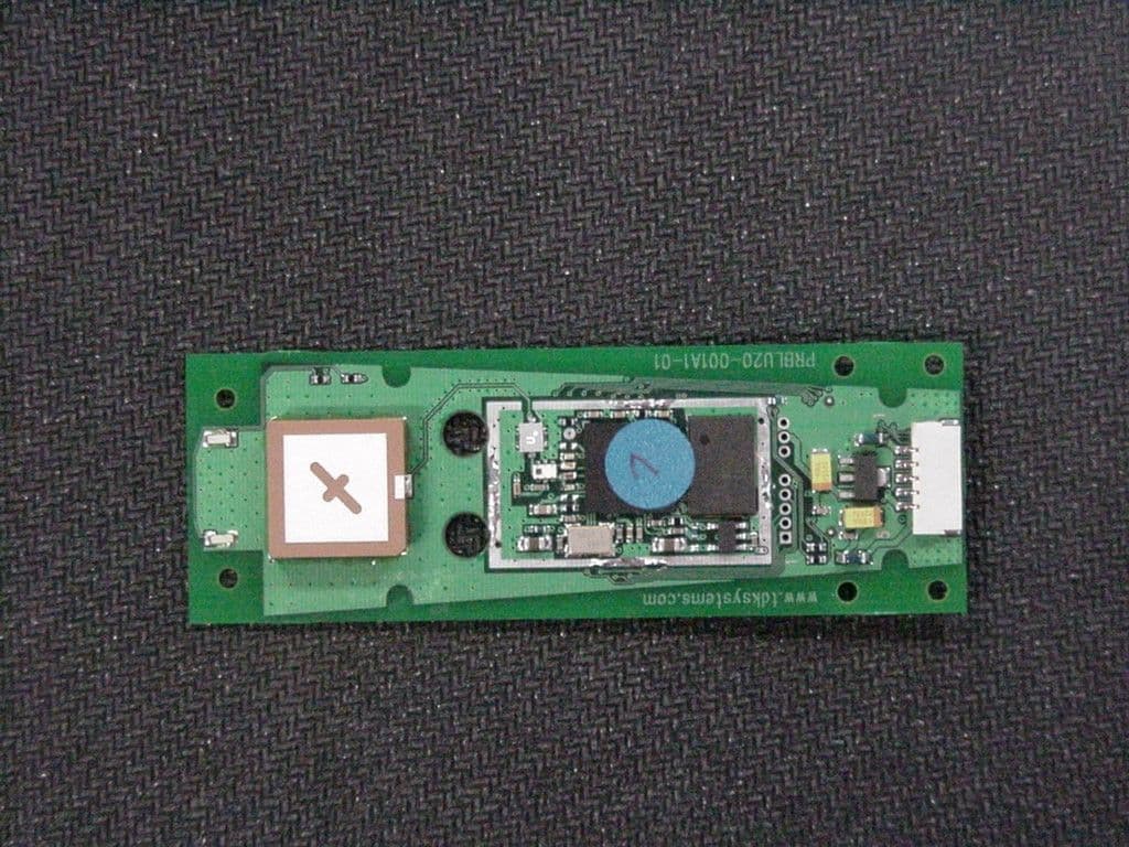
Click to zoom
Application Details
- Equipment Class
- DSS - Part 15 Spread Spectrum Transmitter
- Date of Grant
- Mar 05, 2003
- Application Purpose
- Original Equipment
- Date of Application
- Mar 05, 2003
- Equipment Note
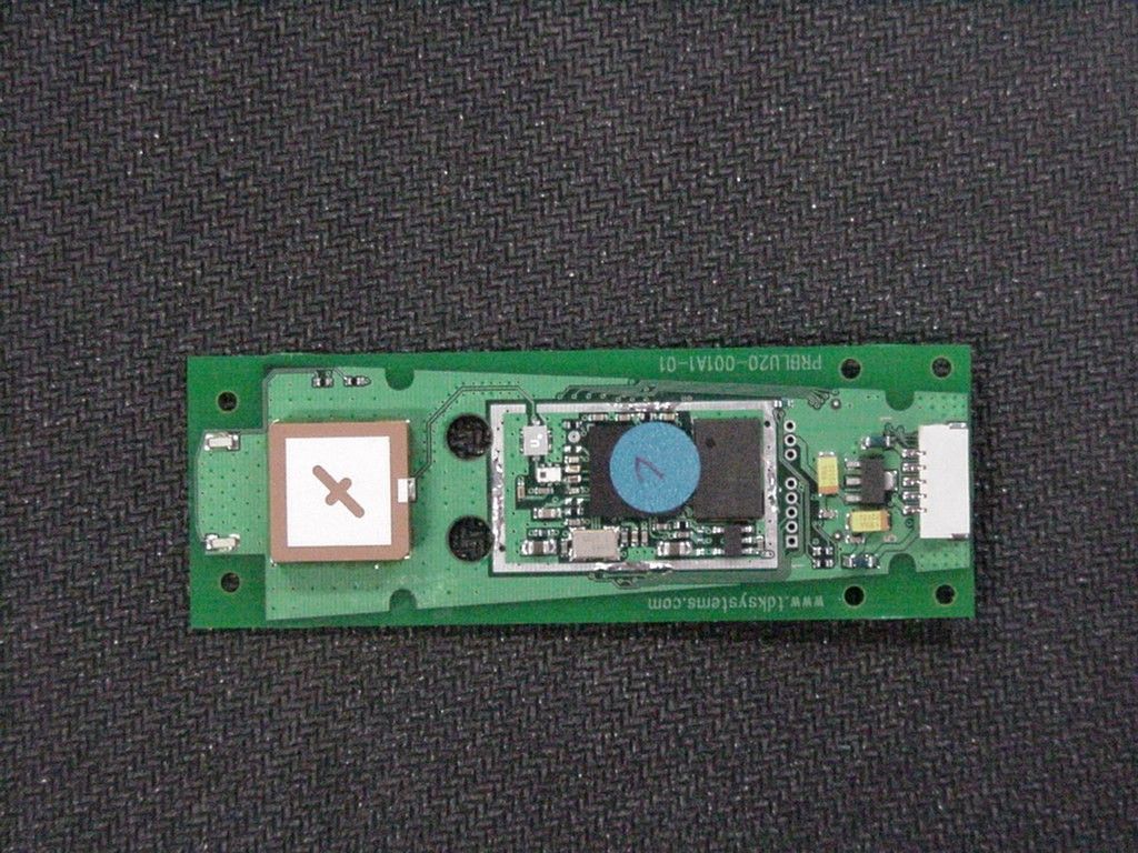
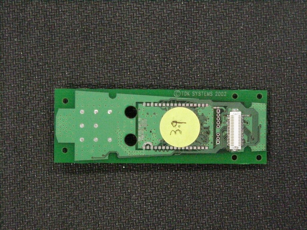
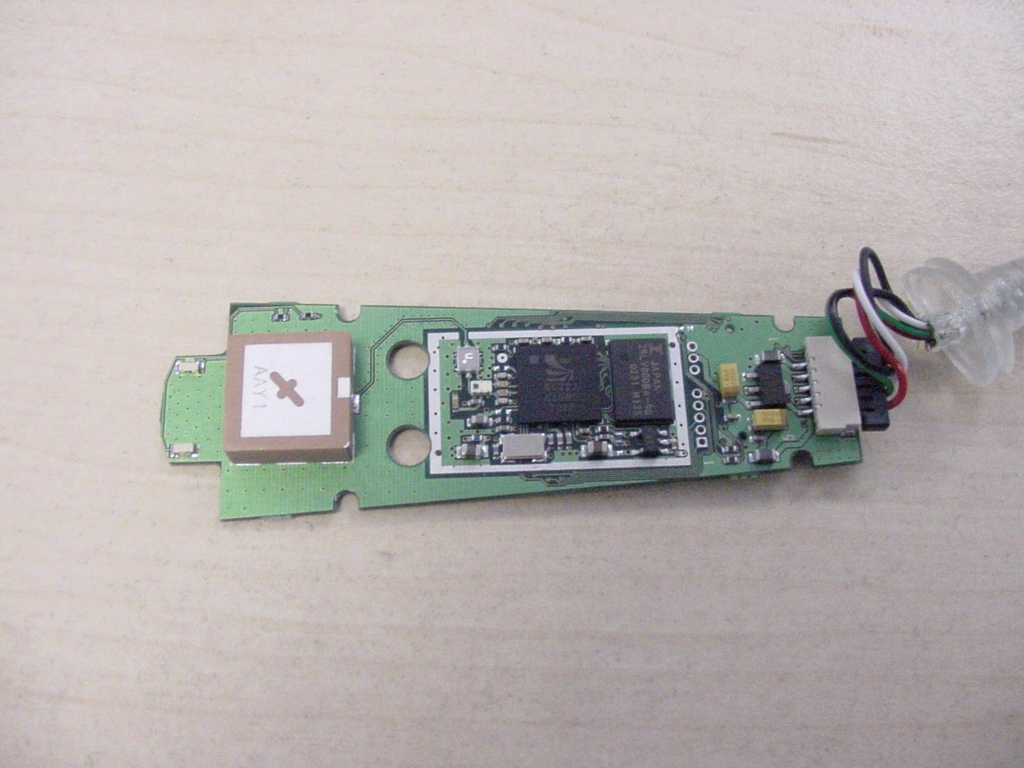
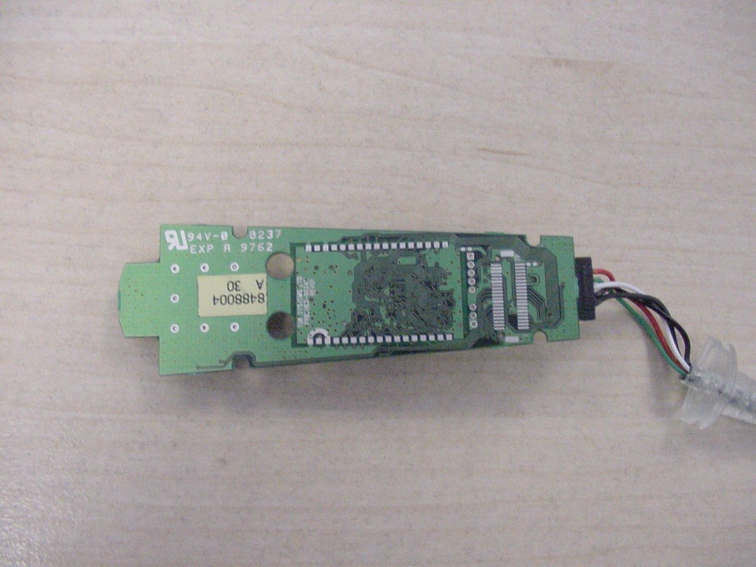
- Bluetooth Intelligent Serial Module
- Frequency Range
- 2402.00000000 - 2480.00000000
- Company
- Laird Connectivity, LLC
- Country
- United States
Documents & Files
Document Text
Text extracted from the exhibit documents filed with the FCC. Open a document above to read the original.
Users Manual
SERIAL MODULE MOTHERBOARD USER MANUAL By: Nick Letheren Date: January 2003 Thank you for purchasing the TDK Bluetooth Intelligent Serial Module Motherboard. This board allows the TDK Intelligent Serial Module to be connected to a PC. Related documents: • Serial Module Hardware Interface Description • TDK Bluetooth AT Serial Module Software Description Circuit Description for Motherboard Basically there 3 parts to the motherboard. RS232 Serial interface. This provides a direct interface to any standard RS232 port on a PC or peripheral. Component U2 is a level shifter on the RX, TX, CTS, RTS, DTR, DSR, RI signals that converts between the 3.3V required on the module to the standard RS232 level. 9-way D type connector (J2) is configured so that it will directly connect to the Serial port of a PC. Audio interface. Connector J9 allows a headset or audio source to be connected to the Intelligent Serial Module. The PCM signals from the Serial module are converted by CODEC (U4) to analog output. The Mic input is passed via the CODEC to the PCM input of the module. The circuit is designed to drive a simple mobile phone type headset. Flash upgrade interface. The 25-way D type connector (J1) allows the Intelligent Serial Module to be reflashed using the Bluelab utilities provided by CSR. The connector is organised so that a direct one-to-one cable to the parallel port of a PC will allow the utilities to run. The Audio and Flash upgrade circuit are on one half of the PCB so that they could be removed in applications using the RS232 interface only. The board is designed so that if the wire links are removed it can be snapped in two parts. Software The motherboard and Intelligent Serial Module will connect to the Serial Port of any PC. The user can simply communicate with the module using any Terminal Emulator software such as Hyper-terminal or Procomm. An alternative Emulator is included on the CD . “TDK Terminal” is a terminal emulation application capable of running on Windows 98/ME/2000/XP operating systems. It was developed specifically to aid development and testing of TDK’s Bluetooth Serial Module. It allows connection to serial devices using any combination of the following communications parameters:- Comport: 1 to 255 Baudrate: 300 to 921600 Parity: None, Odd, Even Data Bits: 7 or 8 Stop Bits 1 or 2 Handshaking: None or Cts/Rts Differentiating features with respect to other terminal emulation applications are:- Status of DSR, CTS, DCD and RI are continuously displayed DTR can be directly controlled via a check box RTS can be directly controlled BREAK signals can be sent Finally, there is a “DATA TRANSFER TEST” mode which allows data to be sent as fast as the handshaking will allow. This feature is very useful for testing the bit transfer of a Bluetooth connection. To run the TDK Terminal expand the file TDKterminal.zip and copy the .exe file into a working directory. Simply run TDKterminal.exe, instructions are provided. Interface Specification Serial port connector (J2) Pin Signal I/O Pin Signal I/O 1 CD O 8 CTS O 6 DSR O 4 DTR I 2 RX O 9 RI O 7 RTS I 5 GND 3 TX I Parallel port connector (J1) Pin Signal Description Pin Signal Description 1 n/c 14 n/c 2 SPI_CSB 15 n/c 3 n/c 16 SPI_RST 4 n/c 17 n/c 5 n/c 18 n/c 6 n/c 19 n/c 7 n/c 20 GND 8 SPI_MOSI 21 GND 9 SPI_CLK 22 GND 10 SPI_MISO 23 GND 11 n/c 24 GND 12 n/c 25 GND 13 n/c Power connector (J7) Pin Sign al Description 1 (centre pin) Vcc Nominal 5V (3.6v-6v) 2,3 (outer) GND Headset connector (J9) Pin Signal Description 1 GND 2 MIC IN Audio Input 3 H/S OUT Audio output 4 n/c Jumpers Jumper Signal Description J5 PC DTR Optional link to power the board from DTR from PC J8 Power input No link, used as alternative power input Electrical Characteristics Parameter Min Typ Max UnitsComments RS232 Inputs Voltage range -25 25 Threshold Low 0.8 1.4 V Threshold High 2.0 2.4 V hysteresis 0.6 V I/P resistance 3 5 7 kΩ RS232 Outputs Voltage swing ±5.0 ±5.4 V Loaded 3kΩ O/P resistance 300 50k Ω O/P short cct ±40 ±100 mA Parameter Min Typ Max UnitsComments Power Supply Input Voltage 3.6 5 6 V Current mA Parameter Min Typ Max UnitsComments Audio Interface Headset Impedance 300 Ω Headset o/p voltage 1.78 V Mic common mode range 1.2 2.1 V
Users Manual
© TDK Systems Europe Ltd 2003 Bluetooth Serial Module AT Command Set Doc No: XRBLU020-001SW-0 Issue No : 1.9 Date : 3 Feb 2003 Page 1 of 38 Author : Mahendra Tailor Bluetooth Serial Module AT Command Set Prepared by : Mahendra Tailor Authorised by: Signature : Signature : © 2003 COPYRIGHT TDK Systems Europe Ltd This document is issued by TDK Systems Europe Limited (hereinafter called TDK) in confidence, and is not to be reproduced in whole or in part without the prior written permission of TDK. The information contained herein is the property of TDK and is to be used only for the purpose for which it is submitted and is not to be released in whole or in part without the prior written permission of TDK. Bluetooth Serial Module AT Command Set Date : 3 Feb 03 Issue No : 1.9 Doc No : XRBLU020-001SW-0 Page 2 of 38 © TDK Systems Europe Ltd 2003 Change History Issue Description Author Date 1.0 First Draft M Tailor 4-Oct-2002 1.1 *) Added S registers 504,530,531 *) Added commands AT+BTR & AT+BTA *) Audio capability *) Added Chapter “Asynchronous Responses” M Tailor 16-Oct-02 1.2 *) Added S Registers 533 and 534 M Tailor 31-Oct-02 1.3 *) Updated Pin Designation on 40 way connector M Tailor 1 Nov 02 1.4 *) Added S Register 535 M Tailor 12 Nov 02 1.5 *) Error in AT Command sequence in the pure cable replacement chapter corrected *) Removed paragraph regarding unilateral acceptance of incoming call – not an issue anymore *)Added the “Frequently Asked Questions” Chapter *)Added NickH’s comments M Tailor 6 Dec 02 1.6 *) Updated the “pure cable replacement” chapter *) Added the AT&F* command for completely erasing the nvram M Tailor 9 Dec 02 1.7 *) AT+BTI now returns ERROR 27 if S Reg 518 is set too high *) ERROR 17,18 and 19 no longer reported *) New Asynchronous response => PAIR n <bd_addr> *) Version = 0.3.6 *) S Reg 533 now takes value 0 to 2 inclusive *) Added S Reg 525 M Tailor 2 Jan 03 1.8 *) Added the Motherboard Chapter M Tailor 14 Jan 03 1.9 *)Corrected details for SReg 508 to 511 inclusive *)AT&F command modified *)Added Power Consumption Chapter M Tailor 3 Feb 03 Bluetooth Serial Module AT Command Set Date : 3 Feb 03 Issue No : 1.9 Doc No : XRBLU020-001SW-0 Page 3 of 38 © TDK Systems Europe Ltd 2003 Contents 1. Introduction 5 2. AT Command Set 6 2.1 Assumptions ....................................................................................................................................6 2.2 Commands ......................................................................................................................................6 2.2.1 AT................................................................................................................................6 2.2.2 ATZ {Hardware Reset}.........................................................................................6 2.2.3 ATEn {Enable/Disble Echoes} .............................................................................7 2.2.4 AT&Fn {Set S Reg Defaults}................................................................................7 2.2.4 AT&F* {Clear NonVolatile Storage}....................................................................7 2.2.5 AT&W {Write S Regs to Non-Volatile Memory} ...................................................7 2.2.6 ATIn {Information} ................................................................................................8 2.2.7 ATSn=m {Set S Register} ....................................................................................9 2.2.6 Future S Registers ......................................................................................................10 2.2.8 ATSn? {Query S Register} ...................................................................................11 2.2.9 ATD<bd_addr> {Make Connection}.....................................................................11 2.2.10 ATDU<bd_addr> {Make Authenticated Connection} ...........................................11 2.2.11 ATDY<bd_addr> {Make Encrypted Connection} .................................................11 2.2.12 ATDUY<bd_addr> {Make Encrypted/Authenticated Connection} .......................11 2.2.13 ATDYU<bd_addr> {Make Encrypted/Authenticated Connection} .......................11 2.2.14 +++ {Enter Command Mode} ................................................................................11 2.2.15 ^^^ {Enter Command Mode} .................................................................................12 2.2.16 ATA {Answer Call} ...............................................................................................12 2.2.17 ATH {Drop Connection} .......................................................................................12 2.2.18 ATO {Enter Online Mode} (letter ‘o’) ...................................................................12 2.2.19 AT+BTO<devclass> {Open and make Unit Detectable} .....................................12 2.2.20 AT+BTI<devclass> {Inquire}.................................................................................12 2.2.21 AT+BTIV<devclass> {Inquire}..............................................................................13 2.2.22 AT+BTIN<devclass> {Inquire}..............................................................................13 2.2.23 AT+BTX {Disable Page/Inquiry Scanning} ..........................................................13 2.2.24 AT+BTQ {Enable Inquiry Scans ONLY} ..............................................................13 2.2.25 AT+BTG {Enable Promiscuous Page Scanning ONLY}......................................13 2.2.26 AT+BTGU {Enable Promiscuous Page Scanning ONLY} ...................................13 2.2.27 AT+BTGY {Enable Promiscuous Page Scanning ONLY} ...................................14 2.2.28 AT+BTGUY {Enable Promiscuous Page Scanning ONLY}.................................14 2.2.29 AT+BTGYU {Enable Promiscuous Page Scanning ONLY}.................................14 2.2.30 AT+BTG<bd_addr> {Enable Cautious Page …
Text truncated - open the document above for the full version.
Attestation Statements
DECLARATION OF IDENTITY TDK Bluetooth Intelligent Serial Module We hereby declare that the Bluetooth Intelligent Serial Module, FCC ID: PI4_TDK_BTISM, is identical to the Bluetooth USB Adaptor II, FCC-ID: PI4_USBadaptorII. The only difference is that Bluetooth Intelligent Serial Module does not have a housing because it is designed for the use inside of electronic equipment, and will be directly mounted to the host motherboards. It is not intended for external connection to a PC. For and on behalf of TDK Systems Europe Ltd Nick Letheren Research and Development Manager 25 th February 2003
Attestation Statements
Registergericht? registered in:Vorstand? Board of Directors:7 layers AG, Borsigstrasse 11 Ratingen, HRB 3264Dr. Wolfgang Dahm40880 Ratingen, Germany Aufsichtsratsvorsitzende ? Dr. Hans-Jürgen MeckelburgPhone: +49 (0) 2102 749 0 Chairman of the Supervisory Board:Fax: +49 (0) 2102 749 350 Dr. Sabine Grobeckerwww.7Layers.com Peter de Wit 22 April 2003 Phone: +31 (0) 6 22 47 00 55 Fax: +31 (0) 46 442 2192 Email: [email protected] request for a Limited Modular Approval - FCC ID: PI4_TDK_BTISM Dear Application Examiner, TDK Systems Europe are requesting for a modular approval for the device ‘Bluetooth Intelligent Serial Module’. As the device is considered an OEM installation, according to FCC Public Notice DA00-1407, a Limited Modular Approval could be granted. The further requirements of the FCC Public notice DA00-1407 are met: 1. The modular transmitter must have its own RF shielding The radio portion of the module is contained in its own RF shielding. See photos in exhibits. 2. The modular transmitter must have buffered modulation/data inputs The modulation/Data inputs are buffered. 3. The modular transmitter must have its own power supply regulation The modular transmitter has its won power supply regulation. FCC Federal Communications Commission 4_TDK_0502_BTT - 2 - 4. The modular transmitter must comply with the antenna requirements of Section 15.203 and 15.204c The transmitter shall only be used with the tested internal antenna. 5. The modular transmitter must be tested in a stand-alone configuration The EUT was tested in the requested a stand-alone configuration. 6. The modular transmitter must be labelled with its own FCC ID number The EUT will be labelled with its own FCC ID number. The label is specified in related exhibit. If the module is installed inside of an end-product, the label will not be visible. In this case the OEM customer will be instructed to how to apply the exterior label. 7. The modular transmitter must comply with any specific rule or operating requirements applicable to the transmitter and the manufacturer must provide adequate instructions along with the module to explain any such requirements. The EUT is compliant with all applicable FCC rules. Detail instructions are given in the Users Guide. 8. The modular transmitter must comply with any applicable RF exposure requirements. The maximum measured power output is 3,3 mW (5,19 dBm), the maximum antenna gain is 2 dBi = numeric gain 1,585 (see also FCC test report) The maximum permissible exposure is defined in 47 CFR 1.1310 with 1 mW/cm². The distance from the EUT's transmitting antenna where the exposure level reaches the maximum permitted level is calculated using the general equation: S = P*G / 4?R² S max = 1mW/cm², P = 3,3 mW, linear power gain relative to the isotropic radiator = 2,0 dBi = 1,585 (numeric gain), R = distance in cm Solving for R, the 1mW/cm² limit is reached in a distance of 0,645 cm to the transmitting antenna. After installation of the Serial Module, the minimum distance of 0,645 cm must always be ensured. During normal use of the Serial Module it is impossible that the user gets closer to the transmitting antenna. Please contact us if you have any additional questions. Best Regards 7layers AG
Cover Letter(s)
Attn: Reviewing Engineer Federal Communications Commission 7435 Oakland Mills Road Columbia, MD 21046 RE: CONFIDENTIALITY REQUEST FOR ‘TDK Bluetooth Intelligent Serial Module’, FCC-ID: PI4_TDK_BTISM To Whom It May Concern: This letter serves as an official request for confidentiality under the FCC Rule Section 0.459. We have requested that the schematic diagrams, Parts list, Block diagram, PCB layout and Parts placement required to be submitted with this application be withheld from public review. The reason for this request is that these documents are company proprietary information that should never get into the possession of competitors, which would be harmful for our business. Do not hesitate to contact me if you have any additional questions. Thank you very much.
ID Label/Location Info
Updated 10/03/2003 TDK Part Number CKGB-00067-03 Approved by IDA For use in Singapore. DB101279 FCC ID: PI4-TDK-BTISMCanada: 1931-TDK-BTISM LISTED I.T.E ACCESSORY 4T50 systems
Operational Description
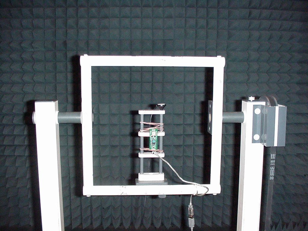
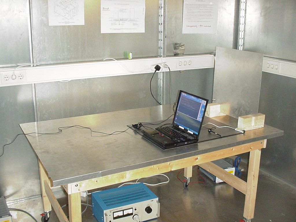
3. Testobject Data Type Designation: Kind of Device: (optional) Voltage Type: Voltage level: Equipment under Test: USB Adaptor II Bluetooth (TM) Transceiver DC 5V Ports 3.1 General EUT Description General product description: Bluetooth is a short-range radio link intended to be a cable replacement between portable and/or fixed electronic devices. Bluetooth operates in the unlicensed ISM Band at 2.4 GHz. In the US a band of 83.5 MHz width is available. In this band, 79 RF channels spaced 1MHz apart are defined. The channel is represented by a pseudo-random hopping sequence through the 79 channels. The channel is devided into time slots, with a nominal slot length of 625μs, where each slot corresponds to different RF hop frequencies. The nominal hop rate is 1600 hops/s. All frequencies are equally used. The average time of occupancy is 0.3797 s within a 30 second period. The symbol rate on the channel is 1 Ms/s. The EUT provides the following ports: USB port Enclosure The main components of EUT are listed and described in Chapter 3.2 Page 8 of 59 Testreport Reference: 4_TDK_0502_BTT_FCCc Short Description Equipment under Test Type Designation 3.2 EUT Main components: Type, S/N, Short Descriptions etc. used in this Test Report HW StatusSW StatusSerial No.Date of Receipt BRBLU03- 002A0-02 Firmware 16.4-11.11.2002USB Adaptor IIUSB TransceiverEUT A EUT A is equipped with an integrated antenna. BRBLU03- 002A0-02 Firmware 16.4-11.11.2002USB Adaptor IIUSB TransceiverEUT B EUT B is equipped with a temporary antenna connector. NOTE: The short description is used to simplify the identification of the EUT in this test report 3.3 Ancillary Equipment Short Description Equipment under Test Type Designation HW StatusSW StatusSerial No.FCC Id For the purposes of this test report, ancillary equipment is defined as equipment which is used in conjunction with the EUT to provide operational and control features to the EUT. It is necessary to configure the system in a typical fashion, as a customer would normally use it. But never the less Ancillary Equipment can influence the test results. AE 1LaptopIBM Thinkpad---- Setup No.Combination of EUTsDescription 3.4 EUT Setups This chapter describes the combination of EUT's and ancillary equipment used for testing. setup 1EUT A + AE1used for radiated measurements setup 2EUT B + AE1used for conducted measurements Page 9 of 59Testreport Reference: 4_TDK_0502_BTT_FCCc Op. Mode Description of Operating Modes Remarks 3.5 Operating Modes This chapter describes the operating modes of the EUT's used for testing. op-mode 1TX mode, the EUT transmits continuously on 2402 MHz op-mode 2TX mode, the EUT transmits continuously on 2441 MHz op-mode 3TX mode, the EUT transmits continuously on 2480 MHz op-mode 4inquiry mode op-mode 5paging mode op-mode 610 neighbouring channelsThe EUT is set to transmit on ten neighbouring channels one after the other to see the channel separation. Page 10 of 59Testreport Reference: 4_TDK_0502_BTT_FCCc 4. Test Results Occupied Bandwidth StandardFCC Part 15, Subpart C The test was performed according to:ANSI C63.4 The test set-up was made in accordance to the general provisions of ANSI C63.4-1992. The Equipment Under Test (EUT) was setup in a shielded room to perform the occupied bandwidth measurements. The reference level is the level of the highest amplitude signal observed from the transmitter at either the fundamental frequency or first-order modulation products in all typical modes of operation, including the unmodulated carrier, even if atypical. The results recorded were measured with the modulation which produce the worst-case (widest) occupied bandwidth. The resolution bandwidth for measuring the reference level and the occupied bandwidth was 10 kHz. The reference level of the spectrum analyser was set equal to the reference level of the EUT. 14. Test Description 10-1-98 1992 Test Limits FCC Part 15, Subpart C, §15.247 (a) (1) (ii) (1) Frequency hopping systems operating in the 2400 - 2483.5 MHz band should use at least 75 hopping frequencies. (2) The average time of occupancy on any frequency should not be greater than 0.4 seconds within a 30 second period. (3) The maximum 20 dB bandwidth of the hopping channel is 1MHz. 4.1.2 4.1.1 4.1.3 Test Protocol 24 °C 1008 hPa 37 % Temperature: Air Pressure: Humidity: Op. Mode op-mode 1 Setup setup 2 Port temporary antenna connector Test Parameter Remarks20 dB Bandwidth MHz 0,8384Please see annex for the measurement plot. noneRemark: Page 11 of 59Testreport Reference: 4_TDK_0502_BTT_FCCc
RF Exposure Info
Torsten Lohoff 24. February 2003 Phone +49 (0) 2102 749 306 Fax +49 (0) 2102 749 350 RF exposure requirements - FCC ID: PI4_TDK_BTISM Dear Application Examiner, The maximum measured power output is 3,3 mW (5,19 dBm), the maximum antenna gain is 2 dBi = numeric gain 1,585 (see also FCC test report) The maximum permissible exposure is defined in 47 CFR 1.1310 with 1 mW/cm². The distance from the EUT's transmitting antenna where the exposure level reaches the maximum permitted level is calculated using the general equation: S = P*G / 4πR² S max = 1mW/cm², P = 3,3 mW, linear power gain relative to the isotropic radiator = 2,0 dBi = 1,585 (numeric gain), R = distance in cm Solving for R, the 1mW/cm² limit is reached in a distance of 0,645 cm to the FCC Federal Communications Commission 2_TDK_0502_TAS
Test Report
EMC Measurement/Technical Report 4_TDK_0502_BTT_FCCc on 7 Layers AG Borsigstr. 11 40880 Ratingen Germany Note: The following test results relate only to the devices specified in this document. This report shall not be reproduced in parts without the written approval of the testing laboratory. Bluetooth (TM) Transceiver USB Adaptor II Registergericht - registered in: Düsseldorf, HRB 44096 Aufsichtratsvorsitzende - Chairman of the Supervisory Board: Dr. Sabine Grobecker Vorstand - Board of Directors: Dr. Wolfgang Dahm Dr. Hans-Jürgen Meckelburg 7 layers AG, Borsigstrasse 11 40880 Ratingen, Germany Phone: +49 (0) 2102 749 0 Fax: +49 (0) 2102 749 350 http://www.7Layers.com Report Reference: TTI-P-G 178/99 Table of Contents 0. Summary 0.1 Technical Report Summary 0.2 Measurement Summary 1. Administrative Data 1.1 Testing Laboratory 1.2 Project Data 1.3 Applicant Data 1.4 Manufacturer Data 3. Testobject Data 3.1 General EUT Description 3.2 EUT Main Components 3.3 Ancillary Equipment 3.4 EUT Setups 3.5 Operating Modes 4. Measurement Results Conducted Emissions Occupied Bandwidth Peak Power Output Spurious RF Conducted Emissions 5. Testequipment 6. Foto Report 7. Setup Drawings 3 3 4 6 6 6 6 6 8 8 9 9 9 10 11 11 14 17 28 31 33 35 Spurious RF Radiated Emissions 19 2. Product Labeling 2.1 FCC ID Label 2.2 Location of Label on the EUT 7 7 7 Dwell Time Power Density Channel Separation Processing Gain 23 25 27 4.1 4.2 4.3 4.4 4.5 4.6 4.7 8. Annex Page 2 of 59Testreport Reference: 4_TDK_0502_BTT_FCCc 0 Summary 0.1 Technical Report Summary Type of Authorization Certification for an Intentional Radiator (Frequency Hopping Spread Spectrum) Applicable FCC Rules: Prepared in accordance with the requirements of FCC Rules and Regulations as listed in 47 CFR Ch.1 Parts 0 to 19 (10-1-98 Edition). The following subparts are applicable to the results in this test report. Part 2, Subpart J - Equipment Authorization Procedures, Certification Sections Part 15, Subpart C - Intentional Radiators § 15.201 Equipment authorization requirement § 15.207 Conducted limits § 15.209 Radiated emission limits; general requirements § 15.247 Operation within the bands 902-928 MHz, 2400-2483,5 MHZ and 5725-5850 MHz Summary Test Results: The EUT complied with all the applicable FCC rules as listed above. Note: The tests were selected and performed with reference to the FCC Public Notice DA 00- 705, released March 30, 2000 Page 3 of 59 Testreport Reference: 4_TDK_0502_BTT_FCCc 0.2 Measurement Summary § 15.247 (a) (1) (ii)FCC Part 15, Subpart C ANSI C63.41992 The measurement was performed according to Occupied Bandwidth OP-ModeSetupPortFinal Result setup 2op-mode 1temporary antenna connectorpassed setup 2op-mode 2temporary antenna connectorpassed setup 2op-mode 3temporary antenna connectorpassed setup 2op-mode 4temporary antenna connectorpassed setup 2op-mode 5temporary antenna connectorpassed § 15.247 (b) (1)FCC Part 15, Subpart C FCC §15.3110-1-1998 The measurement was performed according to Peak Power Output OP-ModeSetupPortFinal Result setup 2op-mode 1temporary antenna connectorpassed setup 2op-mode 2temporary antenna connectorpassed setup 2op-mode 3temporary antenna connectorpassed setup 2op-mode 4temporary antenna connectorpassed setup 2op-mode 5temporary antenna connectorpassed § 15.247 (c)FCC Part 15, Subpart C FCC §15.3110-1-1998 The measurement was performed according to Spurious RF Conducted Emissions OP-ModeSetupPortFinal Result setup 2op-mode 1temporary antenna connectorpassed setup 2op-mode 2temporary antenna connectorpassed setup 2op-mode 3temporary antenna connectorpassed § 15.247 (c), §15.35 (b), § 15.209FCC Part 15, Subpart C ANSI C63.41992 The measurement was performed according to Spurious Radiated Emissions OP-ModeSetupPortFinal Result setup 1op-mode 1enclosurepassed setup 1op-mode 2enclosurepassed setup 1op-mode 3enclosurepassed § 15.247(f)FCC Part 15, Subpart C FCC §15.3110-1-1998 The measurement was performed according to Dwell Time OP-ModeSetupPortFinal Result setup 2op-mode 4temporary antenna connectorpassed setup 2op-mode 5temporary antenna connectorpassed § 15.247 (d)FCC Part 15, Subpart C Page 4 of 59 Testreport Reference: 4_TDK_0502_BTT_FCCc FCC §15.3110-1-1998 The measurement was performed according to Power Density OP-ModeSetupPortFinal Result setup 2op-mode 4temporary antenna connectorpassed setup 2op-mode 5temporary antenna connectorpassed § 15.247 (a) (1)FCC Part 15, Subpart C FCC §15.3110-1-1998 The measurement was performed according to Channel Separation OP-ModeSetupPortFinal Result setup 2op-mode 6temporary antenna connectorpassed Responsible for Accreditation Scope: Responsible for Test Report: Page 5 of 59Testreport Reference: 4_TDK_0502_BTT_FCCc 1. Administrative Data 1.1 Testing Laboratory Company Name: Address: The test facility is also accredited by the following accreditation organisation: Responsible for Accreditation Scope: 7 Layers AG Borsigstr. 11 40880 Ratingen Germany DAR-Registration no. TTI-P-G 178/99 Dipl.-Ing Bernhard Retka Dipl.-Ing Arndt Stöcker Dipl.-Ing Thomas Hoell This facility has been fully described in a report submitted to the FCC and accepted in a letter dated February 07, 2000 under the registration number 96716. - Deutscher Akkreditierungs Rat 11.11.2002 Dipl.-Ing. Thomas Hoell 27.02.2003 11.11.2002-13.11.2002 Responsible for testing and report Receipt of EUT: Date of Test(s): Date of Report: 1.2 Project Data TDK Systems Europe Ltd. Mike Walshe 126 Colindale Avenue Colindale, London NW9 5HD UK please see Applicant data 1.4 Manufacturer Data Company Name: Address: Contact Person: Company Name: Address: Contact Person: 1.3 Applicant Data Page 6 of 59 Testreport Reference: 4_TDK_0502_BTT_FCCc 2.0 Product Labeling 2.1 FCC ID Label: At the time of this report there was no label available. 2.2 Location of Label on the EUT: see above Page 7 of 59Testreport Reference: 4_TDK_0502_BTT_FCCc 3. Testobject Data Type Designation: Kind of Device: (optional) Voltage Type: Voltage l…
Text truncated - open the document above for the full version.
Test Report
Registergerichth registered in:Vorstandh Board of Directors:7 layers AG, Borsigstrasse 11 Ratingen HRB 3264Dr. Wolfgang Dahm40880 Ratingen, Germany AufsichtsratsvorsitzendehDr. Hans-Jürgen MeckelburgPhone: +49 (0) 2102 749 0 Chairman of the Supervisory Board:Fax: +49 (0) 2102 749 350 Dr. Sabine Grobeckerwww.7layers.com Annex Additional declaration part according FCC 15.247 for Bluetooth TM Devices Version: 2002-06-01 Annex - Additional declaration part according FCC 15.247 for Bluetooth devices Page 2 of 5 pages 1 Output power and channel separation of a Bluetooth device in the different operating modes: The different operating modes (data-mode, acquisition-mode) of a Bluetooth device don’t influence the output power and the channel spacing. There is only one transmitter which is driven by identical input parameters concerning these two parameters. Only a different hopping sequence will be used. For this reason the check of these RF parameters in one op-mode is sufficient. 2 Frequency range of a Bluetooth device: Hereby we declare that the maximum frequency of this device is: 2402 – 2480 MHz. This is according the Bluetooth Core Specification (+ critical errata) for devices which will be operated in the USA. This was checked during the Bluetooth Qualification tests (Test Case: TRM/CA/04-E). Other frequency ranges ( e.g. for Spain, France, Japan) which are allowed according the Core Specification are not supported by this device. 3 Co-ordination of the hopping sequence in data mode to avoid simultaneous occupancy by multiple transmitters: Bluetooth units which want to communicate with other units must be organised in a structure called piconet. This piconet consist of max. 8 Bluetooth units. One unit is the master the other seven are the slaves. The master co-ordinates frequency occupation in this piconet for all units. As the master hop sequence is derived from its BD address which is unique for each Bluetooth device, additional masters intending to establish new piconets will always use different hop sequences. 4 Example of a hopping sequence in data mode: Example of a 79 hopping sequence in data mode: 40, 21, 44, 23, 42, 53, 46, 55, 48, 33, 52, 35, 50, 65, 54, 67, 56, 37, 60, 39, 58, 69, 62, 71, 64, 25, 68, 27, 66, 57, 70, 59, 72, 29, 76, 31, 74, 61, 78, 63, 01, 41, 05, 43, 03, 73, 07, 75, 09, 45, 13, 47, 11, 77, 15, 00, 64, 49, 66, 53, 68, 02, 70, 06, 01, 51, 03, 55, 05, 04 Annex - Additional declaration part according FCC 15.247 for Bluetooth devices Page 3 of 5 pages 5 Equally average use of frequencies in data mode and behaviour for short transmissions: The generation of the hopping sequence in connection mode depends essentially on two input values: 1. LAP/UAP of the master of the connection 2. Internal master clock The LAP (lower address part) are the 24 LSB’s of the 48 BD_ADDRESS. The BD_ADDRESS is an unambiguous number of every Bluetooth unit. The UAP (upper address part) are the 24 MSB’s of the 48 BD_ADDRESS. The internal clock of a Bluetooth unit is derived from a free running clock which is never adjusted and is never turned off. For synchronisation with other units only offset are used. It has no relation to the time of the day. Its resolution is at least half the RX/TX slot length of 312.5 μs. The clock has a cycle of about one day (23h30). In most case it is implemented as 28 bit counter. For the deriving of the hopping sequence the entire LAP (24 bits), 4 LSB’s (4 bits) (Input 1) and the 27 MSB’s of the clock (Input 2) are used. With this input values different mathematical procedures (permutations, additions, XOR…
Text truncated - open the document above for the full version.
Contact Information
Applicant
Brian Petted(Technology Leader)
Technical Contact
TDK Systems Europe Ltd.Darrell Robertson
[email protected]+44 20 8938 1024
126 Colindale Avenue · London · Germany
Non-Technical Contact
TDK Systems Europe Ltd.Darrell Robertson
[email protected]+44 20 8938 1024
Test Firm
7layers AGRobert Machulec
Technical Specifications
| # | Rule Parts | Frequency Range | Power Output |
|---|---|---|---|
| 1 | 15C | 2.40 GHz - 2.48 GHz | 3.00 mW |
Other Applications from Laird Connectivity, LLC
PI4BL600T
Apr 18, 2013BL600 Series Bluetooth Low Energy Module
Equipment Class
DTS - Digital Transmission System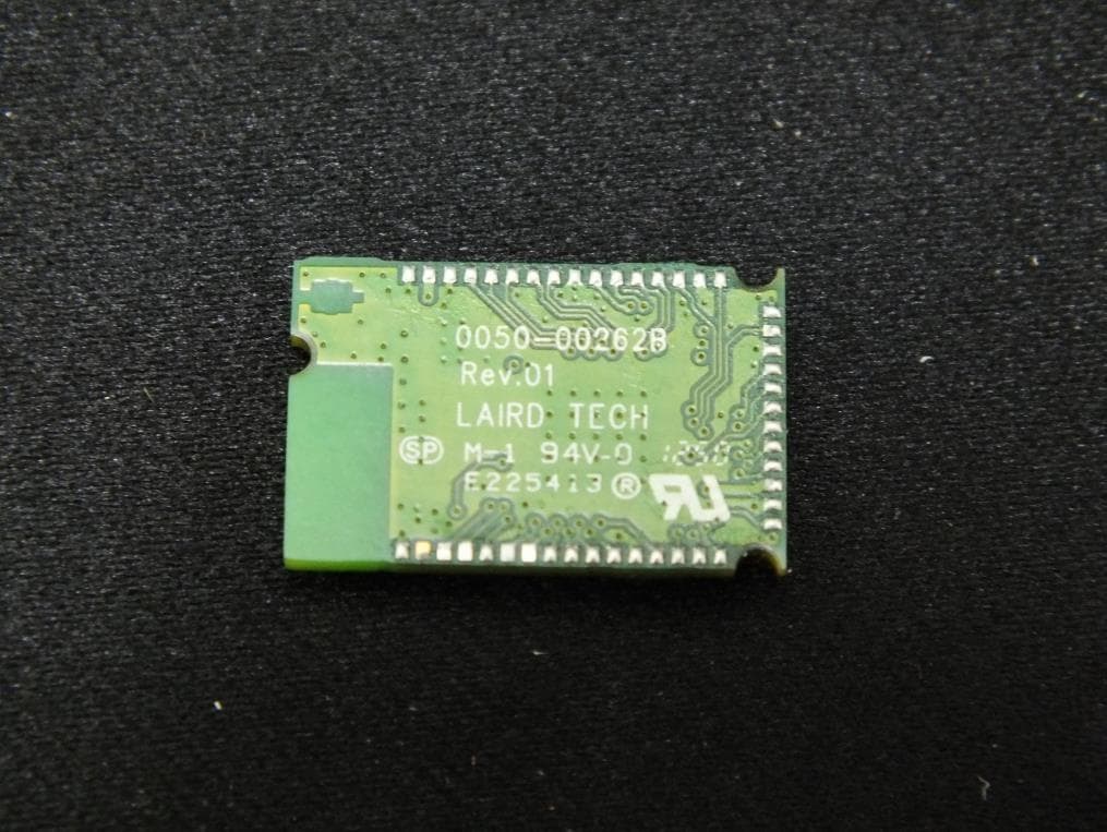
PI4BL600
Apr 11, 2013BL600 Series Bluetooth Low Energy Module
Equipment Class
DTS - Digital Transmission System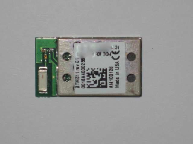
PI4511B
Dec 17, 2009Bluetooth Multimedia Module
Equipment Class
DSS - Part 15 Spread Spectrum Transmitter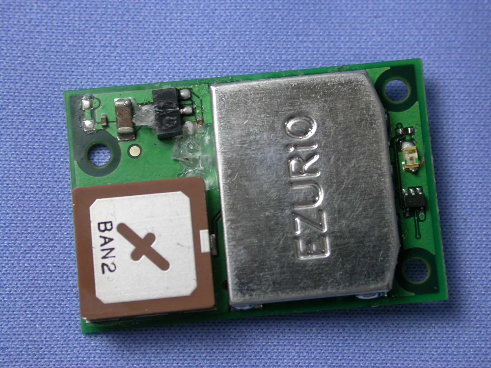
PI407B
Jan 12, 2008Bluetooth Intelligent Serial Module Version II
Equipment Class
DSS - Part 15 Spread Spectrum Transmitter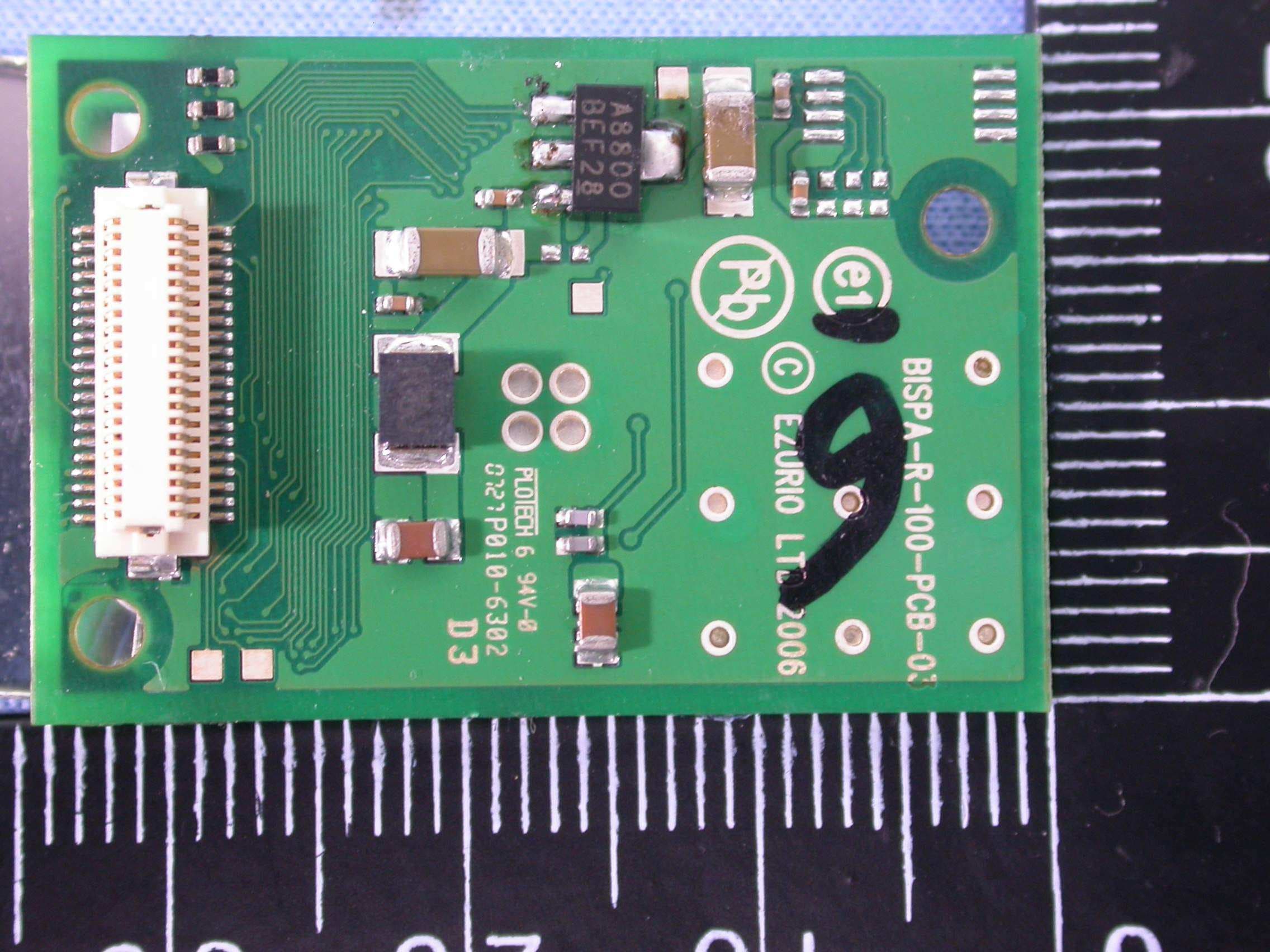
PI409B
Dec 16, 2007BISM PA 3V3
Equipment Class
DSS - Part 15 Spread Spectrum Transmitter