PI403BBluetooth Module
Laird Connectivity, LLC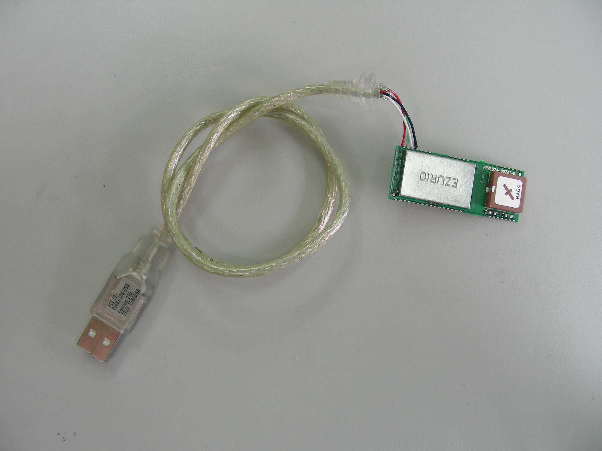
Click to zoom
Application Details
- Equipment Class
- DSS - Part 15 Spread Spectrum Transmitter
- Date of Grant
- Aug 29, 2006
- Application Purpose
- Original Equipment
- Date of Application
- Aug 29, 2006
- Equipment Note
- Bluetooth Module
- Frequency Range
- 2402.00000000 - 2480.00000000
- Company
- Laird Connectivity, LLC
- Country
- United States
Documents & Files
Document Text
Text extracted from the exhibit documents filed with the FCC. Open a document above to read the original.
Users Manual
www.ezurio.com DSH_BT024-00200_1v5 © Ezurio Ltd 2006 1 Embedded Intelligent Bluetooth™ Serial Module Part Number: BISMS02BI-01 1. General Description Ezurio’s Embedded Intelligent Bluetooth Serial Module is a fully integrated and qualified Class 1 Bluetooth solution designed for lowest cost of integration and ownership for designers wishing to include Bluetooth functionality in their products. The module is qualified to Bluetooth Version 2.0. The Embedded Intelligent Bluetooth Serial Module is designed to give a rugged solution that is ideal for industrial automation and ruggedised handheld devices. It works over a wide temperature range of -40°C to +85°C. The physical form of the module allows designers to mount the antenna section of the module outside a screened enclosure. The Embedded Intelligent Serial Module is based on Cambridge Silicon Radio’s BlueCore4 chipset. The module contains all of the hardware and firmware for a complete Bluetooth solution, requiring no further components. The Module has an integrated, high performance antenna which is matched with the Bluetooth RF and baseband circuitry. The firmware integrated into the module implements the higher layer Bluetooth protocol stack, up to and including the Generic Access Profile (GAP), Service Discovery Profile (SDAP), Serial Port Profile (SPP) and Audio Gateway. A virtual processor is used within the BC04 to implement an AT command processor. This interfaces to the host system over a straight forward serial port using an extensive range of AT commands. The AT command set abstracts the Bluetooth protocol from the host application, saving many months of programming and integration time. It provides extremely short integration times for data oriented cable replacement and voice applications. A low cost development system and integrated RS232 products with the same firmware are available for fast product evaluation and development. An alternative version of firmware is available that provides support for multi-point applications. The Module can be configured so that it can be attached to a ‘dumb’ terminal or attached to a PC or PDA for cable replacement applications. In addition to the Bluetooth functionality, The Embedded Intelligent Serial Module provides access to 6 General I/O lines and one ADC input. These can be configured to extend the UART control or to provide connection to simple devices such as switches or LEDs without requiring any external processing. The GPIO lines can be accessed either via the wired host UART connection, or remotely over the Bluetooth link. Support is also provided for a PCM connection to an external audio codec. The Embedded Intelligent Bluetooth Module is supplied in a small form factor PCB (17.7mm x 46.0mm x 5.0mm), that solders directly. The module includes a high sensitivity, high gain antenna which provides excellent range. Typical open field performance provides ranges of over 250 metres at transmit powers of 4mW. Support is provided for low power modes that make the Embedded Intelligent Bluetooth Module particularly applicable to battery powered installations. The Embedded Intelligent Bluetooth Module is Lead-free and RoHS compliant and supports an industrial operating temperature range of -40°C to +85°C. 1.1 Applications • POS Equipment • Automotive Applications • Industrial Automation • Telematics • Vending Equipment • Medical Bluetooth is a trademark owned by Bluetooth SIG, Inc., USA, and is licensed to Ezurio Ltd www.ezurio.com DSH_BT024-00200_1v5 © Ezurio Ltd 2006 2 2. Features Feature Implementation Bluetooth Transmission Class 1 Fully Bluetooth pre-qualified Bluetooth 2.0 Range 250 metres typical (free space) Frequency 2.400 – 2.485 GHz Max Transmit Power +6dBm Min Transmit Power -27dBm Receive Sensitivity Better than -86dB Data Transfer rate Up to 300Kbps over UART. Serial Interface RS-232 bi-directional for commands and data using AT commands Serial parameters Default 9600,n,8,1 - Configurable from 1,200bps to 961,200 bps. 7 bit firmware is available – please contact Ezurio Support for DTR, DSR, DCD, RI, RTS, CTS Physical size 17.7mm x 46.0mm x 5.0mm, 8g Current consumption Less than 36mA during data transfer in standard power mode. Lower powers are attainable with a configurable low power mode. Low power sniff mode 2.5mA typ Temperature Range Normal operation: -40°C to +85°C Supply Voltage 3.3V – 7.0V Interface Levels 3.0V Logic Audio Audio can be transferred over SCO channels through the PCM interface at 64kbps. PCM can be configured as master or slave. Support for dual slave PCM connections. Profiles Server - SPP (Full), DUN, Audio Gateway, Headset, Handsfree Client - All RFCOMM based profiles Multipoint Max 7 slaves with multipoint Field upgradeable Over UART Protocols Single point firmware is controlled and configured using AT Commands. Standard multipoint firmware uses a simple packet based protocol and requires a host to enable the module to function effectively. Single point only allows a point to point connection whereas multipoint allows more than one simultaneous connection. GPIO 6 x digital (DTR can also be allocated as GPIO) ADC 1 x 8 bit Indicators Pads for 2 programmable LEDs Lead free Lead-free and RoHS compliant www.ezurio.com DSH_BT024-00200_1v5 © Ezurio Ltd 2006 4 3.2 Pin Descriptions The table below defines the pin functions. Refer to the previous section for the pin location Pin No. Signal Description Pin No. Signal Description 1 VCC 2 USB /RESERVED Do not connect 3 USB /RESERVED Do not connect 4 GND 5 RESET- Reset I/P * 6 GPIO_6 I/O for Host 7 GPIO_7 I/O for Host 8-19 N/C Do not Connect 20 GND 21 UART_DCD I/O for Host 22 UART_RI I/O for Host 23 UART_RTS Request to Send O/P 24 UART_RX Receive Data I/P 25 UART_CTS Clear to Send I/P 26 UART_TX Transmit Data O/P 27 UART_DTR (GPIO_3) I/O for Host 28 UART_DSR Input 29 GND 30 PCM_SYNC PCM Sync I/P 31 PCM_IN PCM Data I/P 32 PCM_CLK PCM Clock I/P 33 PCM_OUT PCM Data O/P 34 GPIO_9 PCM_SLVCLK I/O for Host (Slave PCM …
Text truncated - open the document above for the full version.
Cover Letter(s)
Ezurio Ltd FCC ID: PI403B Request for Full Transmitter Modular Approval Transmitter Module Characteristics per FCC public notice DA 00-1407 requirements Item Requirements EUT 1. Have its own RF shielding The Modular transmitter has it own RF shielding. Please refer to the internal photograph. 2. Have buffered modulation/data inputs (if such inputs are provided), All inputs to the modules are buffered through logic or microprocessor inputs. 3. Have it own power supply regulation The module can regulate Power Supply by itself. (Please refer to Schematic) 4. Meet the antenna requirements of Section 15.203 Device is equipped with unique antenna and complies with the antenna requirements of Section 15.203 and 15.204(c). Refer to internal photos. 5. Be tested in a stand-alone configuration, i.e., the antenna, AC or DC power and data input/output lines must be connected to the module but, the module must not be inside another case during testing Device was tested in a stand-alone configuration, and is capable of complying with part15 emission limits regardless of the device into which it is eventually installed. 6. Be labeled with its own FCC ID number, and if the FCC ID is not visible when the module is installed inside another device, then the outside of the device into which the module is installed must also display a label referring to the enclosed module. The modular transmitter will be labeled with its own FCC ID. Also, the notebook manufacturer will be informed to display a label refer to the enclosed module. The exterior label will read as follows: “Contains FCC ID ”. 7. The modular transmitter is manufactured so that the user cannot influence the operation of the transmitter that will operate outside of the scope of the regulations. The device is to be installed by the application and end user installation is prohibited. 8. Address compliance with the Commission's RF exposure limits in Sections 1.1310 and 2.1093. In addition, under Section 15.247 are required to address RF exposure compliance in accordance with Section 15.247(b)(4). The maximum conducted output power is 1.84dBm (1.53mW). The modular transmitter complies with all applicable RF exposure requirements.
Cover Letter(s)
Dear Sir: Pursuant to Section 0.457 and 0.459 of the Commission’s Rules, the Applicant hereby requests confidential treatment of information accompanying this Application as outlined below: Schematics Block Diagram Operational Descriptions The above materials contain trade secrets and proprietary information not customarily released to the public. The public disclosure of these matters might be harmful to the Applicant and provide unjustified benefits to its competitors. The Applicant understands that pursuant to Rule 0.457, disclosure of this Application and all accompanying documentation will not be made before the date of the Grant for this application.
External Photos
ETC Report No.: ET94S-12-120-01 Page A1 of A1 FCC ID:PI403B ANNEX A: EXTERNAL CONSTRUCTION PHOTOS OF EUT 1. Outside view of EUT
ID Label/Location Info
FCC ID Label_Location FCCID: PI403B IC: 1931B-EUSB Model: TRBLU24-00100 Ezurio Ltd.
Internal Photos
ETC Report No.: ET94S-12-120-01 Page B1 of B1 FCC ID:PI403B ANNEX B: INTERNAL CONSTRUCTION PHOTOS OF EUT 1. Front view of PCB 2. Rear view of PCB
Test Report
ETC Report No. : ET94S-12-120-01 Sheet 1 of 83 Sheets FCC ID: PI403B Rev. No 1.0 CONFORMANCE TEST REPORT FOR FCC 47 CFR, Part 15 Subpart C Report No.: ET94S-12-120-01 Client: Ezurio Limited. Product: Embedded Surface Mount Bluetooth Module Model: TRBLU24-00100 FCC ID: PI403B Manufacturer/supplier: Sanmina SCI Date test item received: 2005/12/14 Date test campaign completed: 2006/07/18 Date of issue: 2006/08/10 The test result only corresponds to the tested sample. It is not permitted to copy this report, in part or in full, without the permission of the test laboratory. Total number of pages of this test report: 83 pages Total number of pages of photos: External photos 1 pages Internal photos 1 pages Setup photos 3 pages Test Engineer Checked By Approved By Mark James Joe Hsieh ELECTRONICS TESTING CENTER, TAIWAN NO.8, LANE 29, WENMING RD., LESHAN TSUEN, GUISHAN SHIANG, TAOYUAN COUNTY, TAIWAN 33383, R.O.C.TAIWAN, R.O.C. TEL: (03) 3276170~4 INT: +886-3-3276170~4 FAX: (03) 3276188 INT: +886-3-3276188 ETC Report No. : ET94S-12-120-01 Sheet 2 of 83 Sheets FCC ID: PI403B Rev. No 1.0 Client : Ezurio Limited. Address : Saturn House, Mercury Park, Wycombe Lane, Wooburn Green HP10 0HH UK Manufacturer : Sanmina SCI Address : 90 MOO 1 TIWANON RD BANMAI, MUNAG PATHUMTHANI 12000 Thailand EUT : Embedded Surface Mount Bluetooth Module Trade name : EZURiO Model No. : TRBLU24-00100 Comment issues : (1) The report also apply to model: TRBLU24-00200、TRBLU24-00300、 TRBLU24-00400、BISMS02BI (2) The multiple listing recognized without test basis is according to information supplied by manufacturer. A detail documentation of the above models must be verified by legal right organization for the EMC characteristic with relation to the subject model. Power Source : Power from USB cable (5.0Vdc) Regulations applied : FCC 47 CFR, Part 15 Subpart C (2006) The testing described in this report has been carried out to the best of our knowledge and ability, and our responsibility is limited to the exercise of reasonable care. This certification is not intended to believe the sellers from their legal and/or contractual obligations. The compliance test is only certified for the test equipment and the results of the testing report relate only to the item tested. The compliance test of this report was conducted in accordance with the appropriate standards. It’s not intention to assure the quality and performance of the product. This report shall not be reproduced except in full, without the approval of ETC. This report must not be used by the client to claim product endorsement by NVLAP or any agency of the U.S. Government. Laboratory Introduction: Electronics Testing Center, Taiwan is recognized, filed and mutual recognition arrangement as following: 1 ISO9001: TüV Product Service 2 ISO/IEC 17025: BSMI, CNLA, DGT, NVLAP, CCIBLAC, UL, Compliance 3 Filing: FCC, Industry Canada, VCCI 4 MRA: Australia, Hong Kong, New Zealand, Singapore, USA, Japan, Korea, China, APLAC through CNLA 5 FCC Registration Number: 90588, 91094, 91095 NVLAP Lab Code 200133-0 ETC Report No. : ET94S-12-120-01 Sheet 3 of 83 Sheets FCC ID: PI403B Rev. No 1.0 Table of Contents Page 1 GENERAL INFORMATION ................................................................................................................ 5 1.1 Product Description................................................................................................................................ 5 1.2 Characteristics of Device ....................................................................................................................... 5 1.3 Test Methodology .................................................................................................................................. 5 1.4 Modifiction List of EUT ........................................................................................................................ 5 1.5 Test Facility............................................................................................................................................ 5 2 PROVISIONS APPLICABLE ............................................................................................................... 6 2.1 Definition ............................................................................................................................................... 6 2.2 Requirement for Compliance................................................................................................................. 7 2.3 Restricted Bands of Operation ............................................................................................................... 9 2.4 Labeling Requirement............................................................................................................................ 9 2.5 User Information.................................................................................................................................. 10 3. SYSTEM TEST CONFIGURATION ................................................................................................. 11 3.1 Justification.......................................................................................................................................... 11 3.2 Devices for Tested System................................................................................................................... 11 4 RADIATED EMISSION MEASUREMENT ..................................................................................... 12 4.1 Applicable Standard............................................................................................................................. 12 4.2 Measurement Procedure....................................................................................................................... 12 4.3 Measuring Instrument .......................................................................................................................... 14 4.4 Radiated Emi…
Text truncated - open the document above for the full version.
Test Report
ETC Report No. : ET94S-12-120-01 Sheet 42 of 83 Sheets FCC ID: PI403B Rev. No 1.0 9 OUT-OF-BAND RF CONDUCTED SPURIOUS EMISSION MEASUREMENT 9.1 Standard Applicable According to 15.247(c), if any 100 kHz bandwidth outside these frequency bands, the radio frequency power that is produced by the modulation products of the spreading sequence, the information sequence and the carrier frequency shall be either at least 20 dB below that in any 100 kHz bandwidth within the band that contains the highest level of the desired power or shall not exceed the general levels specified in § 15.209(a), whichever results in the lesser attenuation. 9.2 Measurement Procedure 1. Check the calibration of the measuring instrument using either an internal calibrator or a known signal from an external generator. 2. The setup of the EUT as shown in figure 4. Turn on the EUT and connect its antenna terminal to measurement instrument via a low loss cable. Then set it to any measured frequency within its operating range and make sure the instrument is operated in its linear range. 3. Set RBW of spectrum analyzer to 100 kHz with a convenient frequency span including 100kHz bandwidth from band edge. 4. Measure the highest amplitude appearing on spectral display and set it as a reference level. Plot the graph with marking the highest point and edge frequency. 5. Repeat above procedures until all measured frequencies were complete. 9.3 Measurement Equipment Equipment Manufacturer Model No. Next Cal. Due Spectrum Analyzer Agilent 8564EC 09/23/2006 ETC Report No. : ET94S-12-120-01 Sheet 43 of 83 Sheets FCC ID: PI403B Rev. No 1.0 9.4 Measurement Data Test Date : Jan. 10, 2006 Temperature : 21 °C Humidity : 70% Channel Test Frequency Range Note Chart 0 2360 MHz - 2440 MHz Lower Band Edge Page 44 78 2443.5 MHz - 2523.5 MHz Upper Band Edge Page 45 0 30 MHz - 25 GHz Page 46 39 30 MHz - 25 GHz Page 47 78 30 MHz - 25 GHz Page 48 Note: Please refer to page 44 to page 48 for chart. ETC Report No. : ET94S-12-120-01 Sheet 44 of 83 Sheets FCC ID: PI403B Rev. No 1.0 ETC Report No. : ET94S-12-120-01 Sheet 45 of 83 Sheets FCC ID: PI403B Rev. No 1.0 ETC Report No. : ET94S-12-120-01 Sheet 46 of 83 Sheets FCC ID: PI403B Rev. No 1.0 ETC Report No. : ET94S-12-120-01 Sheet 47 of 83 Sheets FCC ID: PI403B Rev. No 1.0 ETC Report No. : ET94S-12-120-01 Sheet 48 of 83 Sheets FCC ID: PI403B Rev. No 1.0 ETC Report No. : ET94S-12-120-01 Sheet 49 of 83 Sheets FCC ID: PI403B Rev. No 1.0 10 NUMBER of HOPPING CHANNELS 10.1 Standard Applicable According to 15.247(b)(1), for frequency hopping systems, operating in the 2400-2483.5MHz band employing at least 75 hopping channels 10.2 Measurement Procedure 1. Check the calibration of the measuring instrument using either an internal calibrator or a known signal from an external generator. 2. The setup of the EUT as shown in figure 4. Turn on the EUT and connect its antenna terminal to measurement instrument via a low loss cable. Then set EUT to hopping operating mode and set spectrum analyzer miximum to measure the number of hopping channels. 10.3 Measurement Equipment Equipment Manufacturer Model No. Next Cal. Due Spectrum Analyzer Agilent 8564EC 09/23/2006 10.4 Measurement Data Test Date : Jan. 10, 2006 Temperature : 21 °C Humidity : 70% Number of hopping channels = 79 channels Note: Please refer to page 50 to page 52 for chart. ETC Report No. : ET94S-12-120-01 Sheet 50 of 83 Sheets FCC ID: PI403B Rev. No 1.0 ETC Report No. : ET94S-12-120-01 Sheet 51 of 83 Sheets FCC ID: PI403B Rev. No 1.0 ETC Report No. : ET94S-12-120-01 Sheet 52 of 83 Sheets FCC ID: PI403B Rev. No 1.0 ETC Report No. : ET94S-12-120-01 Sheet 53 of 83 Sheets FCC ID: PI403B Rev. No 1.0 11 HOPPING CHANNEL CARRIER FREQUENCY SEPARATED 11.1 Standard Applicable According to 15.247(a)(1), the frequency hopping system shall have hopping channel carrier frequencies seperated by minimum of 25kHz or the 20dB bandwidth of hopping channel, whichever is greater. Alternatively, frequency hopping systems operating in the 2400-2483.5 MHz band may have hopping channel carrier frequencies that are separated by 25kHz or two-thirds of the 20dB bandwidth of the hopping channel, whichever is greater, provided the systems operate with an output power no greater than 125mW. 11.2 Measurement Procedure 1. Check the calibration of the measuring instrument using either an internal calibrator or a known signal from an external generator. 2. The setup of the EUT as shown in figure 4. Turn on the EUT and connect its antenna terminal to measurement instrument via a low loss cable. Then set it to any measurement frequency within its operating ragne and make sure the instrument is operated in its linear range. 3. Set spectrum analyzer maximum hold to measure channel carrier frequency , then adjust channel carrier frequency to adjacent channel. 4. Repeat above procedure until all measured frequencies were complete. 11.3 Measurement Equipment Equipment Manufacturer Model No. Next Cal. Due Spectrum Analyzer Agilent 8564EC 09/23/2006 ETC Report No. : ET94S-12-120-01 Sheet 54 of 83 Sheets FCC ID: PI403B Rev. No 1.0 11.4 Measurement Data Test Date : Jan. 10, 2006 Temperature : 21 °C Humidity : 70% Channel Frequency (MHz) Hopping Channel Carrier Frequency Separated (MHz) Chart 0 2402 1 Page 55 39 2441 1 Page 56 78 2480 1 Page 57 Note: Please refer to page 55 to page 57 for chart. ETC Report No. : ET94S-12-120-01 Sheet 55 of 83 Sheets FCC ID: PI403B Rev. No 1.0 ETC Report No. : ET94S-12-120-01 Sheet 56 of 83 Sheets FCC ID: PI403B Rev. No 1.0 ETC Report No. : ET94S-12-120-01 Sheet 57 of 83 Sheets FCC ID: PI403B Rev. No 1.0
Test Report
ETC Report No. : ET94S-12-120-01 Sheet 58 of 83 Sheets FCC ID: PI403B Rev. No 1.0 12 POWER SPECTRAL DENSITY 12.1 Standard Applicable According to 15.247(d), for bluetooth device, the peak power spectral density conducted from the intentional radiator to the antenna shall not be greater them 8dBm in any 3kHz band during any time interral of continuous transmission. 12.2 Measurement Procedure 1. Check the calibration of the measuring instrument using either an internal calibrator or a known signal from an external generator. 2. The setup of the EUT as shown in figure 4. Turn on the EUT and connect its antenna terminal to measurement instrument via a low loss cable. Then set it to any measured frequency within its operating range and make sure the instrument is operated in its linear range. 3. Set RBW of spectrum analyzer to 3kHz, VBW to 30 kHz, sweep 300kHz and sweep time 100 sec. 4. Measure the highest amplitude appearing on spectral display and record the level to calculate result data. 5. Repeat above procedures until all frequencies measured were complete. 12.3 Measurement Equipment Equipment Manufacturer Model No. Next Cal. Due Spectrum Analyzer Agilent 8564EC 09/23/2006 ETC Report No. : ET94S-12-120-01 Sheet 59 of 83 Sheets FCC ID: PI403B Rev. No 1.0 12.4 Measurement Data Test Date : Jan. 10, 2006 Temperature : 21 °C Humidity : 70% Channel Frequency (MHz) Reading (dBm) Cable Loss (dB) Power Spectral Density (dBm) FCC Limit (dBm) Chart 0 2402 -11.00 0.5 -10.50 8 Page 60 39 2441 -12.16 0.5 -11.66 8 Page 61 78 2480 -13.33 0.5 -12.83 8 Page 62 Note: Please refer to page 60 to page 62 for chart. ETC Report No. : ET94S-12-120-01 Sheet 60 of 83 Sheets FCC ID: PI403B Rev. No 1.0 ETC Report No. : ET94S-12-120-01 Sheet 61 of 83 Sheets FCC ID: PI403B Rev. No 1.0 ETC Report No. : ET94S-12-120-01 Sheet 62 of 83 Sheets FCC ID: PI403B Rev. No 1.0 ETC Report No. : ET94S-12-120-01 Sheet 63 of 83 Sheets FCC ID: PI403B Rev. No 1.0 13 Dwell Time 13.1 Standard Applicable According to 15.247(a)(1)(iii), frequency hopping system in the 2400-2483.5MHz band employing at least 15 non-overlapping channels. The average time of occupancy on any channel shall not be greater than 0.4 seconds within a period of 0.4 second multiplied by the number of hopping channels employed. 13.2 Measurement Procedure 1. Check the calibration of the measuring instrument using either an internal calibrator or a known signal from an external generator. 2. The setup of the EUT as shown in figure 4. 13.3 Measurement Equipment Equipment Manufacturer Model No. Next Cal. Due Spectrum Analyzer Agilent 8564EC 09/23/2006 13.4 Measurement Data Test Date : Jan. 10, 2006 Temperature : 21 °C Humidity : 70% 13.4.1 DH1 Test period=0.4(second/channel) 79× channel=31.6sec a) 2402MHz dwell time= 420.0 us × 79 800 × 31.6 = 134.4 ms b) 2441MHz dwell time= 420.0 us × 79 800 × 31.6 = 134.4 ms c) 2480MHz dwell time= 420.0 us × 79 800 × 31.6 = 134.4 ms Note: Please refer to page 64 to page 69 for chart. ETC Report No. : ET94S-12-120-01 Sheet 64 of 83 Sheets FCC ID: PI403B Rev. No 1.0 ETC Report No. : ET94S-12-120-01 Sheet 65 of 83 Sheets FCC ID: PI403B Rev. No 1.0 ETC Report No. : ET94S-12-120-01 Sheet 66 of 83 Sheets FCC ID: PI403B Rev. No 1.0 ETC Report No. : ET94S-12-120-01 Sheet 67 of 83 Sheets FCC ID: PI403B Rev. No 1.0 ETC Report No. : ET94S-12-120-01 Sheet 68 of 83 Sheets FCC ID: PI403B Rev. No 1.0 ETC Report No. : ET94S-12-120-01 Sheet 69 of 83 Sheets FCC ID: PI403B Rev. No 1.0
Test Report
ETC Report No. : ET94S-12-120-01 Sheet 70 of 83 Sheets FCC ID: PI403B Rev. No 1.0 13.4.2 DH3 Test period=0.4(second/channel) 79× channel=31.6sec a) 2402MHz dwell time= 1.67 ms × 79 400 × 31.6 = 267.2 ms b) 2441MHz dwell time= 1.67 ms × 79 400 × 31.6 = 267.2 ms c) 2480MHz dwell time= 1.67 ms × 79 400 × 31.6 = 267.2 ms Note: Please refer to page 71 to page 76 for chart. ETC Report No. : ET94S-12-120-01 Sheet 71 of 83 Sheets FCC ID: PI403B Rev. No 1.0 ETC Report No. : ET94S-12-120-01 Sheet 72 of 83 Sheets FCC ID: PI403B Rev. No 1.0 ETC Report No. : ET94S-12-120-01 Sheet 73 of 83 Sheets FCC ID: PI403B Rev. No 1.0 ETC Report No. : ET94S-12-120-01 Sheet 74 of 83 Sheets FCC ID: PI403B Rev. No 1.0 ETC Report No. : ET94S-12-120-01 Sheet 75 of 83 Sheets FCC ID: PI403B Rev. No 1.0 ETC Report No. : ET94S-12-120-01 Sheet 76 of 83 Sheets FCC ID: PI403B Rev. No 1.0 ETC Report No. : ET94S-12-120-01 Sheet 77 of 83 Sheets FCC ID: PI403B Rev. No 1.0 13.4.3 DH5 Test period=0.4(second/channel) 79× channel=31.6sec a) 2402MHz dwell time= 2.9167 ms × 79 260 × 31.6 = 303.337 ms b) 2441MHz dwell time= 2.9167 ms × 79 260 × 31.6 = 303.337 ms c) 2480MHz dwell time= 2.9167 ms × 79 260 × 31.6 = 303.337 ms Note: Please refer to page 78 to page 83 for chart. ETC Report No. : ET94S-12-120-01 Sheet 78 of 83 Sheets FCC ID: PI403B Rev. No 1.0 ETC Report No. : ET94S-12-120-01 Sheet 79 of 83 Sheets FCC ID: PI403B Rev. No 1.0 ETC Report No. : ET94S-12-120-01 Sheet 80 of 83 Sheets FCC ID: PI403B Rev. No 1.0 ETC Report No. : ET94S-12-120-01 Sheet 81 of 83 Sheets FCC ID: PI403B Rev. No 1.0 ETC Report No. : ET94S-12-120-01 Sheet 82 of 83 Sheets FCC ID: PI403B Rev. No 1.0 ETC Report No. : ET94S-12-120-01 Sheet 83 of 83 Sheets FCC ID: PI403B Rev. No 1.0
Test Setup Photos
ETC Report No. : ET94S-12-120-01 Sheet 1 of 3 Sheets FCC ID:PI403B Photos of Radiation Measuring Setup x-axis ETC Report No. : ET94S-12-120-01 Sheet 2 of 3 Sheets FCC ID:PI403B y-axis z-axis ETC Report No. : ET94S-12-120-01 Sheet 3 of 3 Sheets FCC ID:PI403B Photos of Conduction Measuring Setup
Contact Information
Applicant
Brian Petted(Technology Leader)
Test Firm
Electronics Testing Center, TaiwanWill Yauo
Technical Specifications
| # | Rule Parts | Frequency Range | Power Output |
|---|---|---|---|
| 1 | 15C | 2.40 GHz - 2.48 GHz | 1.70 mW |
Other Applications from Laird Connectivity, LLC
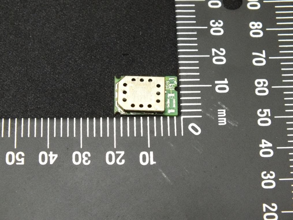
PI4BL600T
Apr 18, 2013BL600 Series Bluetooth Low Energy Module
Equipment Class
DTS - Digital Transmission System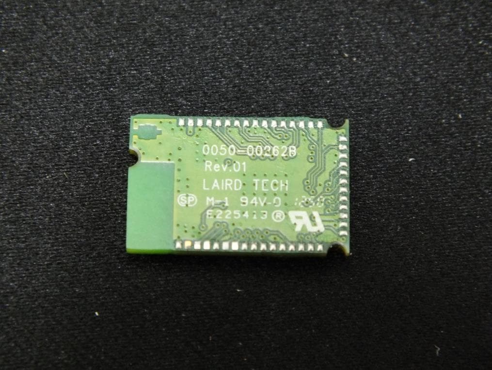
PI4BL600
Apr 11, 2013BL600 Series Bluetooth Low Energy Module
Equipment Class
DTS - Digital Transmission System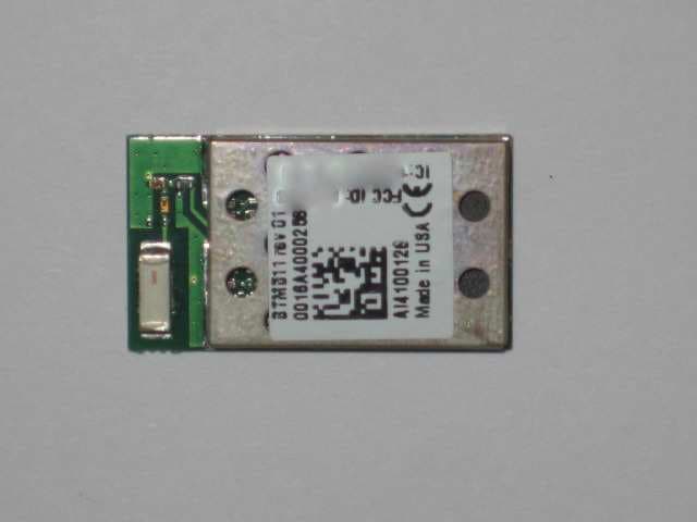
PI4511B
Dec 17, 2009Bluetooth Multimedia Module
Equipment Class
DSS - Part 15 Spread Spectrum Transmitter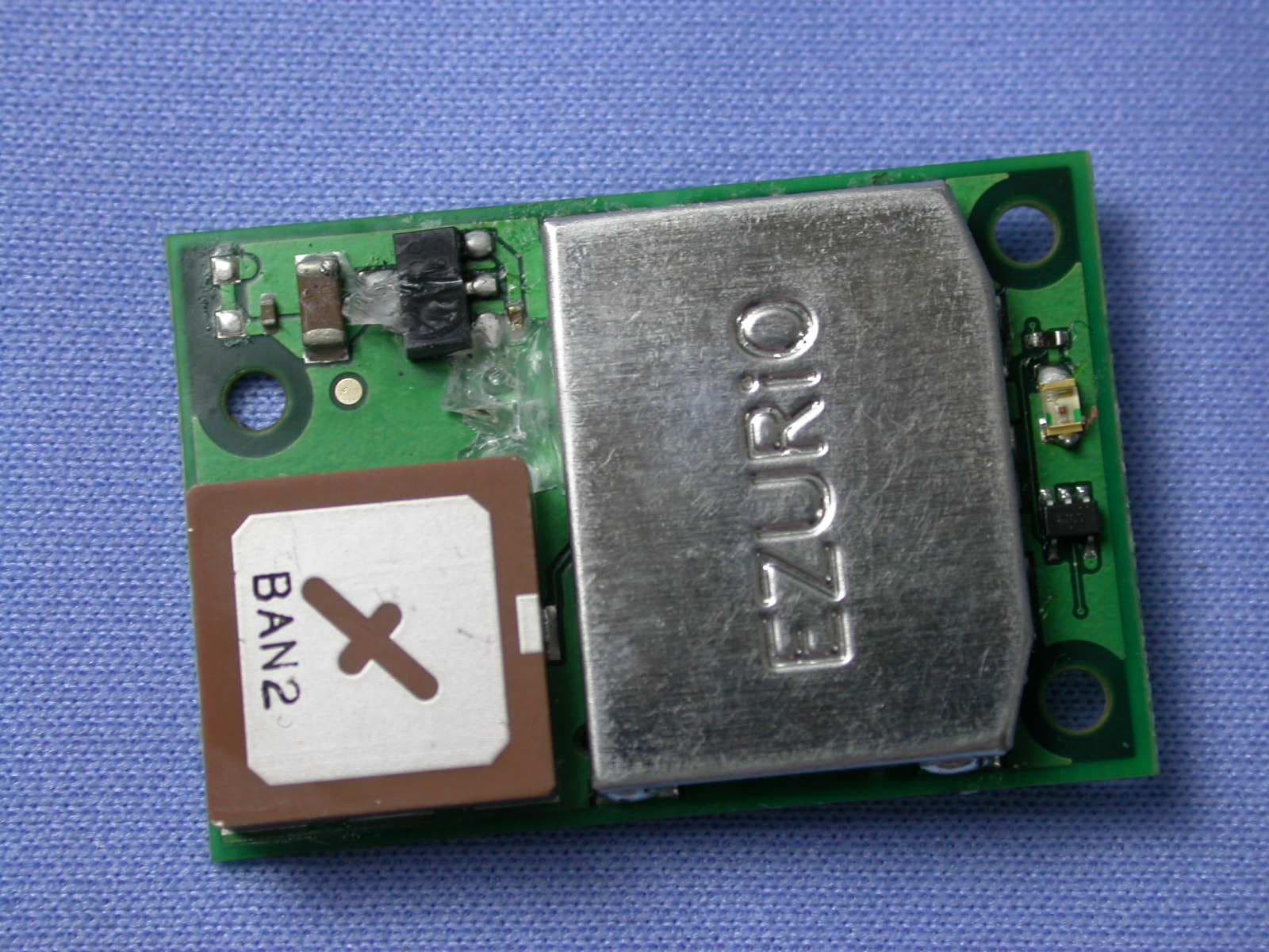
PI407B
Jan 12, 2008Bluetooth Intelligent Serial Module Version II
Equipment Class
DSS - Part 15 Spread Spectrum Transmitter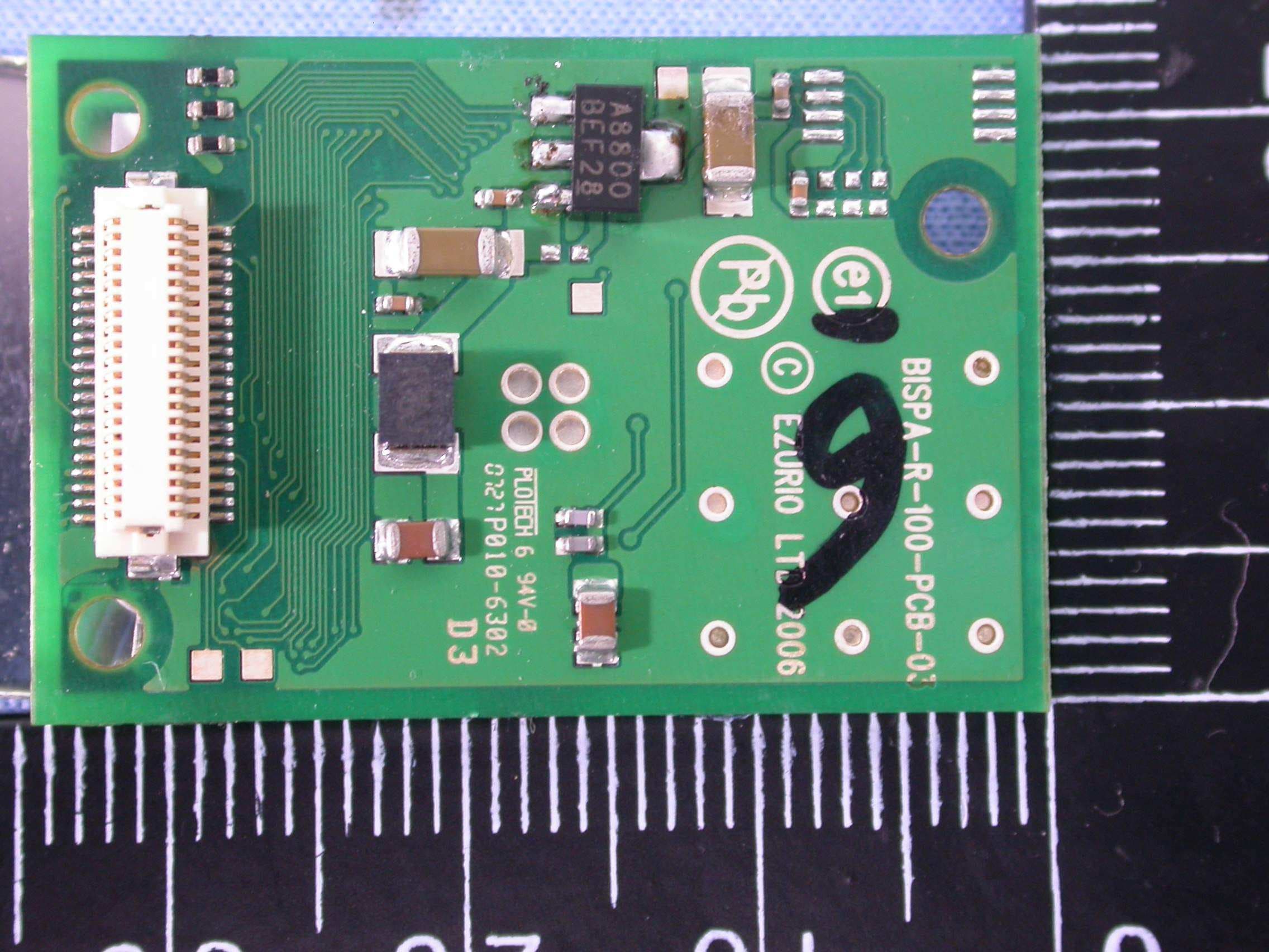
PI409B
Dec 16, 2007BISM PA 3V3
Equipment Class
DSS - Part 15 Spread Spectrum Transmitter