PI404BPhonelabs Bluetooth Module
Laird Connectivity, LLC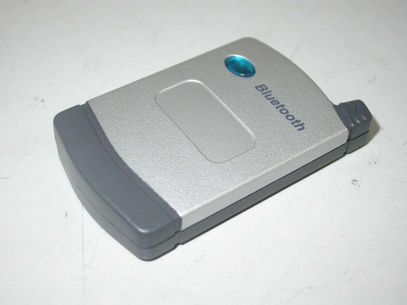
Click to zoom
Application Details
- Equipment Class
- DSS - Part 15 Spread Spectrum Transmitter
- Date of Grant
- Sep 17, 2006
- Application Purpose
- Original Equipment
- Date of Application
- Sep 17, 2006
- Equipment Note
- Phonelabs Bluetooth Module
- Frequency Range
- 2402.00000000 - 2480.00000000
- Company
- Laird Connectivity, LLC
- Country
- United States
Documents & Files
Document Text
Text extracted from the exhibit documents filed with the FCC. Open a document above to read the original.
Users Manual
1 Phonelabs Bluetooth Module User Manual Mechanical 1. The module fit within the existing Phonelabs Bluetooth dongle plastics. 2. The module have a 15 way PCMCIA connector. Power Supply Subsystem Requirements 1. The module operates from 3.3V ±5%. 2. The module consume less than 40mA during audio transfer. Environmental 1. The operating temperature specification for the module be -0 o C to +55 o C 2. The storage temperature range for the module be -40 o C to +85 o C Bluetooth Subsystem 1. The Bluetooth subsystem be based on the Cambridge Silicon Radio BC04 chipset. 2. The module has a minimum receive sensitivity of -84dBm including the antenna gain. 3. The module has an on-board +2 .65dBi antenna. 4. The module has a maximum transmit power of +6dBm including the antenna gain. 5. The module range exceeds 30 ft (free space) whilst meeting the audio performance requirements. NOTE: The maximum effective range of the Bluetooth Module is 30 ft and can be less depending on the levels of competing radio frequency interference. Bluetooth devices transmit and receive in the 2.4Ghz frequency spectrum. There can be interference issues with using a Bluetooth device in the same area as 2.4Ghz cordless phones and WiFi 802.11b & 802.11g, which also operate on the 2.4Ghz frequency. Since 2.4Ghz cordless phones and WiFi 802.11b/g use high power signals in the same 2.4Ghz frequency, they can interfere with lower power devices such as bluetooth. 2 The Dock-N-Talk can also be used with bluetooth equipped cell phones. The PhoneLabs Bluetooth Module allows a wireless bluetooth connection to your cell phone without the need to connect with a cable. Any time you walk into to your home or office your cell phone will be automatically connected to the Dock-N-Talk and instantly ready to make or receive calls using your wireless service. When you leave, the Bluetooth Module will automatically disconnect. Docking the Cell Phone Using the Bluetooth Module If your cell phone is bluetooth enabled, you may connect to the Dock-N-Talk using a Phone Labs Bluetooth Module. To connect your cell phone using the Bluetooth Module, you will need to turn on the bluetooth feature on your cell phone. Be sure that your cell phone is turned on. Then connect the Bluetooth Module to the connector on the right side of the Dock-N-Talk. Press the Bluetooth Pairing button 3 on the right top side of the Dock-N-Talk. Your cell phone should now show you the Dock-N-Talk and ask you if you want to connect. Your cell phone may also require you to enter a password (which is 3774). Once the wireless bluetooth connection has been made, you will see the LED turn from flashing green to solid green color on the Dock-N-Talk and the blue LED on the Bluetooth Module should be illuminated. Confirm that the proper connection has been made. Cell Phone Bluetooth Module Connector Bluetooth Pairing Key Bluetooth devices must be paired before they can communicate. Normally, pairing needs to only be performed once. By pressing the Bluetooth Pairing key for at least two seconds, the Dock-N-Talk will enter into a search mode where it is expecting to receive communication from a bluetooth enabled cellular handset. After the Dock-N-Talk Bluetooth pairing key is pressed, the green LED starts to flash rapidly indicating it is in SEARCH Mode. The user must then initiate bluetooth pairing from the cell phone. The cell phone will prompt the user to enter a password or pass key. The default password is 3774. Once the Dock-N-Talk and cell phone establish a Bluetooth connection, the LED turns solid green to indicate connection to the cell phone. Bluetooth operation requires the Phone Labs Bluetooth Module for functionality. The Bluetooth Module has a similar function to the cable and plugs into the same connector slot on the Dock-N-Talk. NOTE: For best results when using other 2.4Ghz devices, keep those devices as far away as possible from the Dock-N-Talk and cellphone. 4 Enterprise™ Telephone Pair Bluetooth Use this option to pair to your bluetooth enabled cell phone with the Enterprise phone. First you must connect your Bluetooth Module to the Enterprise. You will know if it is properly connected to the Enterprise phone when the display screen says “Module In” and it has a blue flashing light. From the Menu, Press the number 2 key on your Dial Pad or highlight this option using the Up, Down arrows and select the “Choose” Soft Key Button. The LCD screen will discover bluetooth devices. When prompted for a password, enter 3774 on your cell phone dial pad. NOTE: The Bluetooth Module should only need to be paired once to your cell phone unless you change bluetooth cell phones and subsequently pair another cell phone. Once the cell phone is paired to the Bluetooth Module, the blue LED on the Bluetooth Module will turn from a flashing blue state to a steady blue state and the Enterprise phone will light its blue LED located under the LCD screen and you will hear an audible beep. A Soft Key label, BT Off, will appear on the lower left Soft Key. When this Soft Key is pressed, the Bluetooth Module will manually disconnect from the cell phone and a new Soft Key will appear, BT On. Pressing this Soft Key will re-establish the bluetooth connection. These Soft Keys may also be pressed during a call to switch the call back and forth between the cell phone handset and 5 the Enterprise. If you remove the Bluetooth Module, the blue light on the Enterprise will turn off and the LCD screen will read "Module Out" and you will hear an audible beep. NOTE: The Bluetooth Module will automatically connect and disconnect when you move the cell phone in and out of the bluetooth range of approximately 30 feet. If you manually disconnect, the automatic connect feature will not work until the connection is manually re-established. FCC INFORMATION This device complies with Part 15 of the FCC Rules. Operation is subject to the following two conditions: (1) this device may not cause harmful interference, an…
Text truncated - open the document above for the full version.
Cover Letter(s)
FCC 10: PI404B Device Name: Phonelabs Bluetooth Module Model No.: PRBLU48-001A1-02 18:04/09/2006 cccccc~ Federal Communications Commission To whom it may concern: We, the undersigned, hereby authorize ELECTRONICS TESTING CENTER, TAIWAN, to act on our behalf in all manners relating to application for equipment authorization, including signing of all documents relating to these matters. Any and all acts carried out by ELECTRONICS TESTING CENTER, TAIWAN on our behalf shall have the same effect as acts of our own. We, the undersigned, hereby certify that we are not subject to a denial of federal benefits, that includes FCC benefits, pursuant to Section 5301 of the Anti-Drug Abuse Act of 1988,21 U.S.C. 853(a). In authorizing ELECTRONICS TESTING CENTER, TAIWAN as our agent, we still recognize that we are responsible to: a) comply with the relevant provisions of the certification program; b) make all necessary arrangements for the conduct of the evaluation, including provision for examining documentation and access to all areas, records (including internal audit reports) and personnel for the purposes of evaluation (e.g. testing, inspection, assessment, surveillance, reassessment) and resolution of complaints; c) make claims regarding certification only in respect of the scope for which certification has been granted; d) do not use our product certification in such a manner as to bring the Certification Division into disrepute and not make any statement regarding our product certification which the Certification Division may consider misleading or unauthorized; e) upon suspension or cancellation of certification, discontinue use of all advertising matter that contains any reference thereto and return any certification documents as required by the Certification Division; f) use certification only to indicate the products are certified as being in conformity with specified standards; g) endeavor to ensure that no certificate or report nor any part thereof is used in a misleading manner; h) ensure that any reference to our product certification in communication media such as documents, brochures or advertising, complies with the requirements of the Certification Division; i) keep a record of all complaints made known to the us relating to the product compliance with requirements of the relevant standard and to make these records available to the Certification Division when requested; j) take appropriate action with respect to such complaints and any deficiencies found in products or services that affect compliance with the requirements for certification; k) document the actions taken. EZllrlO Lld Saturn House. Me.rcury Park Wyc{)mbe Lane. Woobum Green Bucks HPIO OHH England EZU RiO Tel: +44 (0) 1.628 858940 Fax: +44 (O) ]628518282 www.ezwio.com Registered nun1ber 5178293 This authorization is v id notice from the applicant Sincerely Yours, By: By: M Walshe ~_-:-i8ig:.8tttre,.- - (Printed) Title: Design Engineer Applicant: Ezurio Ltd. Address: Saturn House, Mercury Park, Wycombe Lane, Wooburn Green Bucks HP10 OHH, England Tel: +44 (0) 1628 858 940 Fax: +44 (0) 1628 528 282 Ezurio Ltd Saturn House. Mercury Park Wycombe Lan~. Wooburn Green Bucks HPl 0 OHH England EZU RiO Tel: +44 (0) 1628858940 Fax: +44(0) 1628528282 www.ezuno.com Registered number 5178293
Cover Letter(s)
FCC ID: PI4O48 Device Name: Phonelabs Bluetooth Module Model No.: PRBLU48-001A1-Q2 ~09/2006 Federal Communications Commission Dear Sir: Pursuant to Section 0.457 and 0.459 of the Commission's Rules, the Applicant hereby requests confidential treatment of information accompanying this Application as outlined below: Schematics Block Diagram Operational Descriptions The above materials contain trade secrets and proprietary information not customarily released to the public. The public disclosure of these matters might be harmful to the Applicant and provide unjustified benefits to its competitors. The Applicant understands that pursuant to Rule 0.457, disclosure of this Application and all accompanying documentation will not be made before the date of the Grant for this application (~'i~=:U= By: - - M. Walshe (S' bJ (Printed) : sign Engineer :ant: Ezurio Ltd. ISS : Saturn House, Mercury Park, Wycombe Lane, Wooburn Green, Bucks HP10 OHH : +44 (0)1628 858940 +44 (0)1620 528282 By: Title Applicant: Address: Tel: Fax: . . . Ezuno Ltd Saturn Ho~. Mercury Park Wycontbe Lane. Woobum Green Bucks HPIO OHH England EZU RiO By: Tel: +44 (0) 1628858940 Fax: +44 (0) 1628528282 www.ezwio.coD1 Registered number 5178293
Cover Letter(s)
1 Helen Zhao Subject: FW: Ezurio Ltd, FCC ID: PI404B, Assessment NO.: AN06T6146, Notice#1 Phonelabs uetooth Module Use From: hsieh Sent: Sunday, September 17, 2006 6:33 PM To: Helen Zhao Subject: Re: Ezurio Ltd, FCC ID: PI404B, Assessment NO.: AN06T6146, Notice#1 Dear Helen, Thank you for your mail. Re-Q#1: Attached please find the revise User Manual. Any questions please feel free to contact with me. Best regards, Joe -----Original Message----- From: Helen Zhao Sent: Friday, September 15, 2006 3:32 PM To: Helen Zhao Subject: Ezurio Ltd, FCC ID: PI404B, Assessment NO.: AN06T6146, Notice#1 Question #1: Please revise user manual to add FCC15.19 statement. Best Regards, Helen Zhao The items indicated above must be submitted before processing can continue on the above referenced application. Failure to provide the requested information within 30 days of the original e-mail date may result in application dismissal and forfeiture of the filing fee. Also, please note that partial responses increase processing time and should not be submitted. Any questions about the content of this correspondence should be directed to the e-mail address listed below the name of the sender.
External Photos
ETC Report No.: 06-08-MAS-105-01 Page A1 of A1 FCC ID:PI404B ANNEX A: EXTERNAL CONSTRUCTION PHOTOS OF EUT 1. Outside view 1 of EUT 2. Outside view 2 of EUT
ID Label/Location Info
FCC ID Label Location FCC ID: PI404B Note: 01 Change History 25mm 20mm Industry Canada: 1931B-PLBM Note: 02 Product No: PRBLU48-001A1 Note: 03 Bluetooth Listing No: XXXXXXXXXX Note: 05 Note: 04
Internal Photos
ETC Report No.: 06-08-MAS-105-01 Page B1 of B2 FCC ID:PI404B ANNEX B: INTERNAL CONSTRUCTION PHOTOS OF EUT 1. Inside view of EUT 2. Front view of PCB ETC Report No.: 06-08-MAS-105-01 Page B2 of B2 FCC ID:PI404B 3. Rear view of PCB
Test Report
ETC Report No. : 06-08-MAS-105-01 Sheet 1 of 62 Sheets FCC ID: PI404B Rev. No 1.0 CONFORMANCE TEST REPORT FOR FCC 47 CFR, Part 15 Subpart C Report No.: 06-08-MAS-105-01 Client: Ezurio Ltd. Product: Phonelabs Bluetooth Module Model: BRBLU48-001A1-02 FCC ID: PI404B Manufacturer/supplier: Sanmina-SCI Systems (Thailand) Ltd. Date test item received: 2006/08/14 Date test campaign completed: 2006/09/05 Date of issue: 2006/09/06 The test result only corresponds to the tested sample. It is not permitted to copy this report, in part or in full, without the permission of the test laboratory. Total number of pages of this test report: 62 pages Total number of pages of photos: External photos 1 pages Internal photos 2 pages Setup photos 3 pages Test Engineer Checked By Approved By Jeng De Hsu James Joe Hsieh ELECTRONICS TESTING CENTER, TAIWAN NO.8, LANE 29, WENMING RD., LESHAN TSUEN, GUISHAN SHIANG, TAOYUAN COUNTY, TAIWAN 33383, R.O.C.TAIWAN, R.O.C. TEL: (03) 3276170~4 INT: +886-3-3276170~4 FAX: (03) 3276188 INT: +886-3-3276188 ETC Report No. : 06-08-MAS-105-01 Sheet 2 of 62 Sheets FCC ID: PI404B Rev. No 1.0 Client : Ezurio Ltd. Address : Saturn House, Mercury Park, Wycombe Lane, Wooburn Green Bucks HP10 0HH, England Manufacturer : Sanmina-SCI Systems (Thailand) Ltd. Address : 90 MOO 1 TIWANON RD BANMAI, MUNAG PATHUMTHANI 12000 Thailand EUT : Phonelabs Bluetooth Module Trade name : EZURiO Model No. : BRBLU48-001A1-02 Power Source : 3.3Vdc Regulations applied : FCC 47 CFR, Part 15 Subpart C (2006) The testing described in this report has been carried out to the best of our knowledge and ability, and our responsibility is limited to the exercise of reasonable care. This certification is not intended to believe the sellers from their legal and/or contractual obligations. The compliance test is only certified for the test equipment and the results of the testing report relate only to the item tested. The compliance test of this report was conducted in accordance with the appropriate standards. It’s not intention to assure the quality and performance of the product. This report shall not be reproduced except in full, without the approval of ETC. This report must not be used by the client to claim product endorsement by NVLAP or any agency of the U.S. Government. Laboratory Introduction: Electronics Testing Center, Taiwan is recognized, filed and mutual recognition arrangement as following: 1 ISO9001: TüV Product Service 2 ISO/IEC 17025: BSMI, CNLA, DGT, NVLAP, CCIBLAC, UL, Compliance 3 Filing: FCC, Industry Canada, VCCI 4 MRA: Australia, Hong Kong, New Zealand, Singapore, USA, Japan, Korea, China, APLAC through CNLA 5 FCC Registration Number: 90588, 91094, 91095 NVLAP Lab Code 200133-0 ETC Report No. : 06-08-MAS-105-01 Sheet 3 of 62 Sheets FCC ID: PI404B Rev. No 1.0 Table of Contents Page 1 GENERAL INFORMATION ...................................................................................................................5 1.1 Product Description...................................................................................................................................5 1.2 Characteristics of Device ..........................................................................................................................5 1.3 Test Methodology .....................................................................................................................................5 1.4 Modifiction List of EUT ...........................................................................................................................5 1.5 Test Facility...............................................................................................................................................5 2 PROVISIONS APPLICABLE..................................................................................................................6 2.1 Definition ..................................................................................................................................................6 2.2 Requirement for Compliance ....................................................................................................................7 2.3 Restricted Bands of Operation ..................................................................................................................9 2.4 Labeling Requirement...............................................................................................................................9 2.5 User Information .....................................................................................................................................10 3. SYSTEM TEST CONFIGURATION ....................................................................................................11 3.1 Justification .............................................................................................................................................11 3.2 Devices for Tested System......................................................................................................................11 4 RADIATED EMISSION MEASUREMENT ........................................................................................12 4.1 Applicable Standard................................................................................................................................12 4.2 Measurement Procedure..........................................................................................................................12 4.3 Measuring Instrument .............................................................................................................................14 4.4 Radiated Emission Data..........................................................................................................................15 4.5 Field Strength Calculation.......................................................................................................................22 5 CONDUCTED EMISSIO…
Text truncated - open the document above for the full version.
Test Report
ETC Report No. : 06-08-MAS-105-01 Sheet 45 of 62 Sheets FCC ID: PI404B Rev. No 1.0 10 NUMBER of HOPPING CHANNELS 10.1 Standard Applicable According to 15.247(b)(1), for frequency hopping systems, operating in the 2400-2483.5MHz band employing at least 75 hopping channels 10.2 Measurement Procedure 1. Check the calibration of the measuring instrument using either an internal calibrator or a known signal from an external generator. 2. The setup of the EUT as shown in figure 4. Turn on the EUT and connect its antenna terminal to measurement instrument via a low loss cable. Then set EUT to hopping operating mode and set spectrum analyzer miximum to measure the number of hopping channels. 10.3 Measurement Equipment Equipment Manufacturer Model No. Next Cal. Due Spectrum Analyzer Agilent 8564EC 09/23/2006 10.4 Measurement Data Test Date : Sep. 04, 2006 Temperature : 24 °C Humidity : 53% Number of hopping channels = 79 channels Note: Please refer to page 46 to page 48 for chart. ETC Report No. : 06-08-MAS-105-01 Sheet 46 of 62 Sheets FCC ID: PI404B Rev. No 1.0 ETC Report No. : 06-08-MAS-105-01 Sheet 47 of 62 Sheets FCC ID: PI404B Rev. No 1.0 ETC Report No. : 06-08-MAS-105-01 Sheet 48 of 62 Sheets FCC ID: PI404B Rev. No 1.0 ETC Report No. : 06-08-MAS-105-01 Sheet 49 of 62 Sheets FCC ID: PI404B Rev. No 1.0 11 HOPPING CHANNEL CARRIER FREQUENCY SEPARATED 11.1 Standard Applicable According to 15.247(a)(1), the frequency hopping system shall have hopping channel carrier frequencies seperated by minimum of 25kHz or the 20dB bandwidth of hopping channel, whichever is greater. Alternatively, frequency hopping systems operating in the 2400-2483.5 MHz band may have hopping channel carrier frequencies that are separated by 25kHz or two-thirds of the 20dB bandwidth of the hopping channel, whichever is greater, provided the systems operate with an output power no greater than 125mW. 11.2 Measurement Procedure 1. Check the calibration of the measuring instrument using either an internal calibrator or a known signal from an external generator. 2. The setup of the EUT as shown in figure 4. Turn on the EUT and connect its antenna terminal to measurement instrument via a low loss cable. Then set it to any measurement frequency within its operating ragne and make sure the instrument is operated in its linear range. 3. Set spectrum analyzer maximum hold to measure channel carrier frequency , then adjust channel carrier frequency to adjacent channel. 4. Repeat above procedure until all measured frequencies were complete. 11.3 Measurement Equipment Equipment Manufacturer Model No. Next Cal. Due Spectrum Analyzer Agilent 8564EC 09/23/2006 ETC Report No. : 06-08-MAS-105-01 Sheet 50 of 62 Sheets FCC ID: PI404B Rev. No 1.0 11.4 Measurement Data Test Date : Sep. 04, 2006 Temperature : 24 °C Humidity : 53% Channel Frequency (MHz) Hopping Channel Carrier Frequency Separated (MHz) Chart 0 2402 1 Page 51 39 2441 1 Page 52 78 2480 1 Page 53 Note: Please refer to page 51 to page 53 for chart. ETC Report No. : 06-08-MAS-105-01 Sheet 51 of 62 Sheets FCC ID: PI404B Rev. No 1.0 ETC Report No. : 06-08-MAS-105-01 Sheet 52 of 62 Sheets FCC ID: PI404B Rev. No 1.0 ETC Report No. : 06-08-MAS-105-01 Sheet 53 of 62 Sheets FCC ID: PI404B Rev. No 1.0 ETC Report No. : 06-08-MAS-105-01 Sheet 54 of 62 Sheets FCC ID: PI404B Rev. No 1.0 12 Dwell Time 12.1 Standard Applicable According to 15.247(a)(1)(iii), frequency hopping system in the 2400-2483.5MHz band employing at least 15 non-overlapping channels. The average time of occupancy on any channel shall not be greater than 0.4 seconds within a period of 0.4 second multiplied by the number of hopping channels employed. 12.2 Measurement Procedure 1. Check the calibration of the measuring instrument using either an internal calibrator or a known signal from an external generator. 2. The setup of the EUT as shown in figure 4. 12.3 Measurement Equipment Equipment Manufacturer Model No. Next Cal. Due Spectrum Analyzer Agilent 8564EC 09/23/2006 12.4 Measurement Data Test Date : Sep. 04, 2006 Temperature : 24 °C Humidity : 53% 12.4.1 DH1 Test period=0.4(second/channel) 79× channel=31.6sec 2402MHz dwell time= 395 us × 79 800 × 31.6 = 126.4 ms Note: Please refer to page 55 to page 56 for chart. ETC Report No. : 06-08-MAS-105-01 Sheet 55 of 62 Sheets FCC ID: PI404B Rev. No 1.0 ETC Report No. : 06-08-MAS-105-01 Sheet 56 of 62 Sheets FCC ID: PI404B Rev. No 1.0 ETC Report No. : 06-08-MAS-105-01 Sheet 57 of 62 Sheets FCC ID: PI404B Rev. No 1.0 12.4.2 DH3 Test period=0.4(second/channel) 79× channel=31.6sec 2441MHz dwell time= 1.65 ms × 79 400 × 31.6 = 264.0 ms Note: Please refer to page 58 to page 59 for chart. ETC Report No. : 06-08-MAS-105-01 Sheet 58 of 62 Sheets FCC ID: PI404B Rev. No 1.0 ETC Report No. : 06-08-MAS-105-01 Sheet 59 of 62 Sheets FCC ID: PI404B Rev. No 1.0 ETC Report No. : 06-08-MAS-105-01 Sheet 60 of 62 Sheets FCC ID: PI404B Rev. No 1.0 12.4.3 DH5 Test period=0.4(second/channel) 79× channel=31.6sec 2480MHz dwell time= 2.9 ms × 79 260 × 31.6 = 301.6 ms Note: Please refer to page 61 to page 62 for chart. ETC Report No. : 06-08-MAS-105-01 Sheet 61 of 62 Sheets FCC ID: PI404B Rev. No 1.0 ETC Report No. : 06-08-MAS-105-01 Sheet 62 of 62 Sheets FCC ID: PI404B Rev. No 1.0
Test Setup Photos
ETC Report No. : 06-08-MAS-105-01 Sheet 1 of 2 Sheets FCC ID:PI404B Photos of Radiation Measuring Setup x-axis ETC Report No. : 06-08-MAS-105-01 Sheet 2 of 2 Sheets FCC ID:PI404B y-axis z-axis
Contact Information
Applicant
Brian Petted(Technology Leader)
Test Firm
Electronics Testing Center, TaiwanWill Yauo
Technical Specifications
| # | Rule Parts | Frequency Range | Power Output |
|---|---|---|---|
| 1 | 15C | 2.40 GHz - 2.48 GHz | 2.20 mW |
Other Applications from Laird Connectivity, LLC
PI4BL600T
Apr 18, 2013BL600 Series Bluetooth Low Energy Module
Equipment Class
DTS - Digital Transmission System
PI4BL600
Apr 11, 2013BL600 Series Bluetooth Low Energy Module
Equipment Class
DTS - Digital Transmission System
PI4511B
Dec 17, 2009Bluetooth Multimedia Module
Equipment Class
DSS - Part 15 Spread Spectrum Transmitter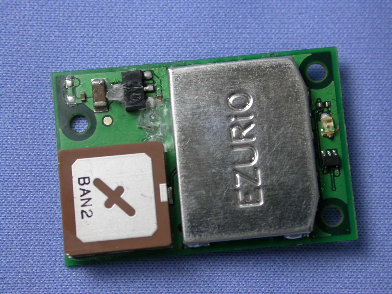
PI407B
Jan 12, 2008Bluetooth Intelligent Serial Module Version II
Equipment Class
DSS - Part 15 Spread Spectrum Transmitter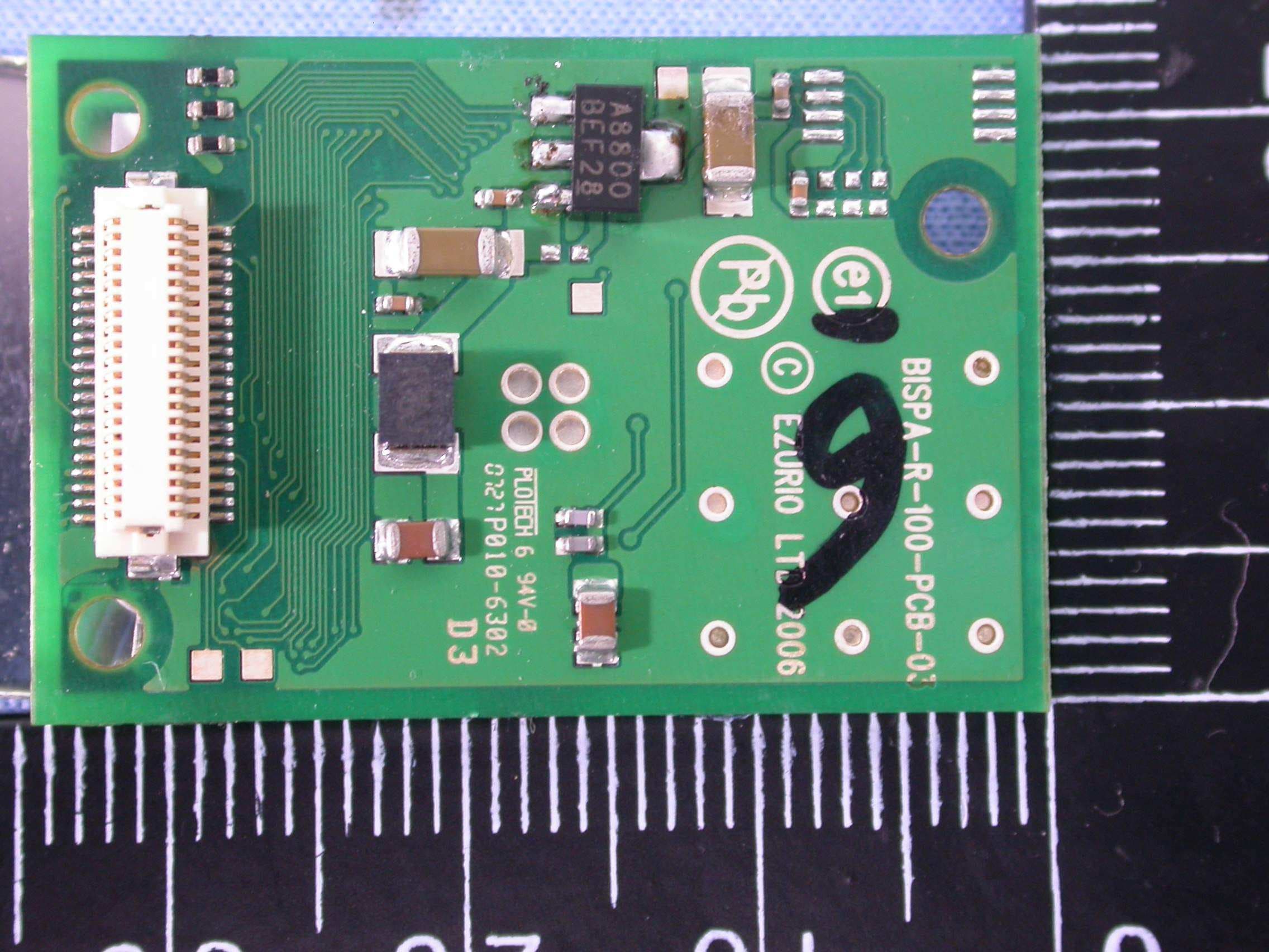
PI409B
Dec 16, 2007BISM PA 3V3
Equipment Class
DSS - Part 15 Spread Spectrum Transmitter