PI408BBISM PA
Laird Connectivity, LLC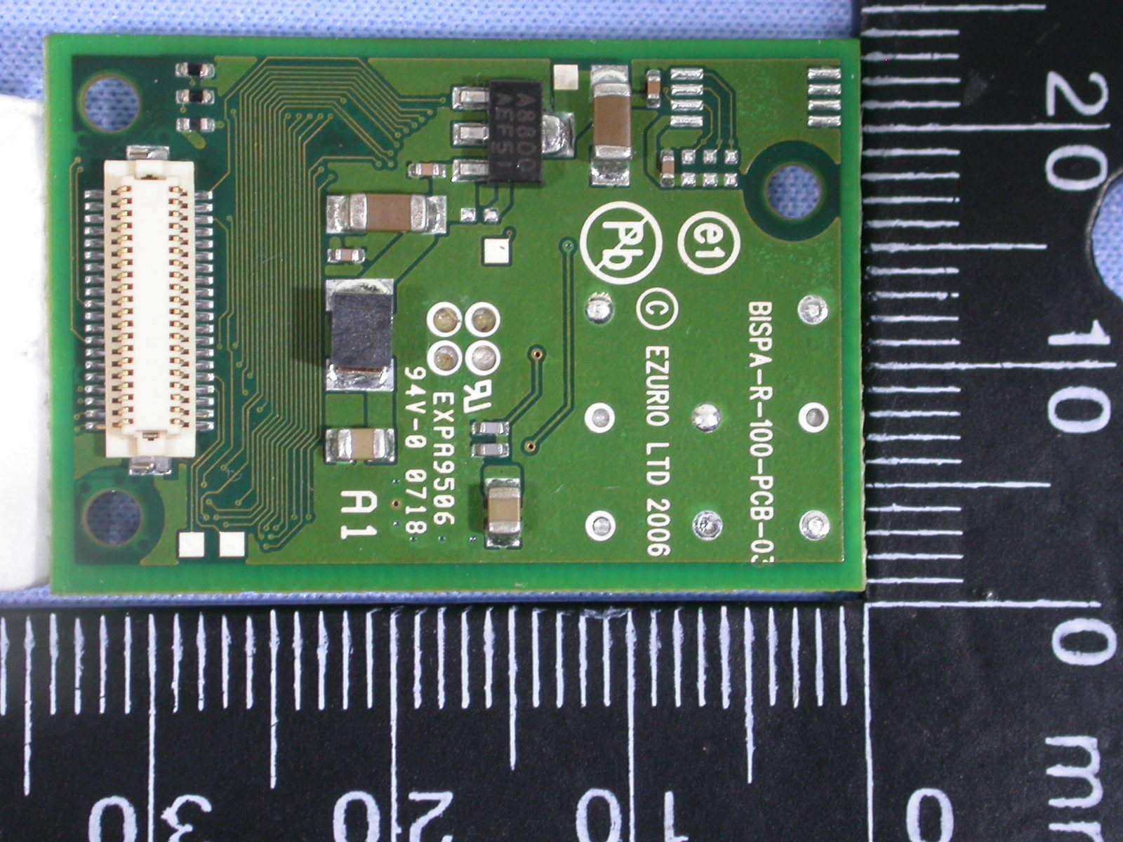
Click to zoom
Application Details
- Equipment Class
- DSS - Part 15 Spread Spectrum Transmitter
- Date of Grant
- Nov 19, 2007
- Application Purpose
- Original Equipment
- Date of Application
- Nov 19, 2007
- Equipment Note
- BISM PA
- Frequency Range
- 2402.00000000 - 2480.00000000
- Company
- Laird Connectivity, LLC
- Country
- United States
Documents & Files
Document Text
Text extracted from the exhibit documents filed with the FCC. Open a document above to read the original.
Users Manual
www.EZURiO.com DSH_BTM402_0v72 BISM2 PA Data Sheet.DOC © 2007 EZURiO Ltd 1 Long Range Bluetooth™ Serial Module Bluetooth Module with Power Amplifier Part Number: BTM402 1. General Description EZURiO’s BISM II PA Bluetooth Serial Module is a fully integrated and qualified Class 1 Bluetooth solution, which incorporates a power amplifier and low noise amplifier that maximises the RF link budget to provide the greatest range of any Bluetooth Module. The module is designed for lowest cost of integration and ownership for designers wishing to incorporate Bluetooth functionality into their products. The module is qualified to Bluetooth Version 2.0. The BISM II PA Bluetooth Serial Module is one of the most compact complete Bluetooth solutions, making it ideal to integrate into handheld devices. The module includes a high sensitivity, high gain antenna which provides excellent range. Typical open field performance provides ranges of up to 1,000 metres at transmit powers of 80mW. The BISM II PA Module is based on Cambridge Silicon Radio’s BlueCore 04 chipset. The module contain all of the hardware and firmware for a complete Bluetooth solution, requiring no further components. The Module has an integrated, high performance antenna which is matched with the Bluetooth RF and baseband circuitry. The firmware integrated into the BC04 chipset implements the higher layer Bluetooth protocol stack, with support for applications requiring Generic Access Profile (GAP), Service Discovery Profile (SDAP), Serial Port Profile (SPP), Dial Up Networking Profile (DUN), Headset Profile (HSP), Hands Free Profile (HFP), File Transfer Profile (FTP) and OBEX (Client). A virtual processor is used within the BC04 to implement an AT command processor. This interfaces to the host system over a straight forward serial port using an extensive range of AT commands. The AT command set abstracts the Bluetooth protocol from the host application, saving many months of programming and integration time. It provides extremely short integration times for data oriented cable replacement and voice applications. Firmware is also included that provides programming support for multi-point applications. A low cost development system is available for fast product evaluation and development. Support is provided for low power modes that make the BISM II PA particularly applicable to battery powered installations. The Module can be configured so that it can be attached to a ‘dumb’ terminal or attached to a PC or PDA for cable replacement applications. In addition to the Bluetooth functionality, The BISM II PA Module provides access to 9 General I/O lines and 2 analogue input lines. These can be configured to provide connection to simple devices such as switches or LEDs without requiring any external processor. Both the GPIO and ADC lines can be accessed either via the wired host UART connection, or remotely over the Bluetooth link. The BISM II PA module is supplied in a small form factor pcb (22.0mm x 34.0mm x 7.6mm), that connects to a main pcb using a 40 way Hirose connector. The interface is compatible with the BISM1 module and EZURiO’s 40 pin 802.11 modules. The BISM II PA module is Lead-free and is RoHS compliant and supports an industrial temperature range of -20°C to +85°C. A key feature of the design is that the module is pin and format compatible with EZURiO’s range of 802.11 wireless LAN modules. This allows designers to manufacture a single version of pcb which can accept either a Bluetooth or an 802.11 module, greatly reducing development time to generate a range of wirelessly enabled products. The compatible 802.11 modules are the WISMC01, which contains a full TCP/IP stack, network drivers and a web server, and the WISMC02 which contains wireless network drivers and a UDP stack with SLIP interface. www.EZURiO.com DSH_BTM402_0v72 BISM2 PA Data Sheet.DOC © 2007 EZURiO Ltd 2 1.1 Applications • POS Equipment • Medical Equipment • Telematics • Voice Applications • Industrial Automation • Automotive Applications 2. Features Feature Implementation Wireless Specification Standards Supported Bluetooth v2.0 Transmit Class Class 1 Frequency 2.400 – 2.4835 GHz Channels 79 channels Frequency Hopping Adaptive Frequency Hopping Max Transmit Power +19 dBmi from integrated antenna +17 dBm @ antenna connector (option) Min Transmit Power -27 dBmi from integrated antenna Receive Sensitivity -87 dBm Data Transfer rate Up to 300kbps Range Up to 1,000 metres free space Antenna Modes Integrated Antenna High performance +2dBi multilayer ceramic External Antenna (option) 50 Ohm U.FL connection UART Interface Serial Interface RS-232 bi-directional for commands and data 16550 compatible Baud Rate Configurable from 1,200 to 921,600bps Non-standard baud rates supported Bits 7 or 8 Parity Odd, even, none Stop bits 1 or 2 Default Serial parameters 9,600,n,8,1 Levels 3.0V CMOS Modem Control DTR, DSR, DCD, RI, RTS, CTS † General Purpose Interface I/O 9 general purpose I/O pins, 3.0V CMOS † ADC 2 ADC inputs. 8 bit, 1.8V max Audio Support 3 PCM Channels @ 64kbps SCO Channels Support SCO and eSCO PCM Interface Configurable as master or slave 8 bit A-law 8 bit μ-law 13 bit linear PCM Clock available when in slave mode www.EZURiO.com DSH_BTM402_0v72 BISM2 PA Data Sheet.DOC © 2007 EZURiO Ltd 3 Protocols & Firmware Bluetooth Stack V2.0 compliant. Fully integrated. Profiles GAP (Generic Access Profile) SDP (Service Discovery Profile) SPP (Serial Port Profile) FTP Client Advertised Profiles DUN (Dial Up Networking) FTP Server Headset (Audio Gateway) Handsfree (Audio Gateway) Profile Components Audio Gateway Generic OBEX Push/Pull Client Firmware Upgrade Available over UART Connection Modes Point to point (cable replacement) Multipoint – max 7 slaves Command Interface AT Instructions set Comprehensive control of connection and module operation S Registers for non-volatile storage of parameters Multipoint Software Supports multiple connections Current Consumption Data Trans…
Text truncated - open the document above for the full version.
Cover Letter(s)
1 Lucy Tsai From: Joe Hsieh [[email protected]] Sent: Sunday, November 18, 2007 6:44 PM To: Lucy Tsai Subject: Re: Ezurio Ltd, FCC ID: PI408B, Assessment NO.: AN07T7361, Notice#1 Attachments: Operational Decription.pdf; 07-10-MAS-192-01_External Photos.pdf; 07-10-MAS-192-01 _Internal Photos.pdf; BTM402 User Manual.pdf Dear Lucy, Re Q#1: Attached please find the new "Operation Description" document. Re Q#2: Attached please find the revised "User Manual" document. Re Q#3: Attached please find the separate Internal Photos and External Photos document. Any questions please feel free to contact with me. Thanks. Best regards, Joe ----- Original Message ----- From: Lucy Tsai To: [email protected] ; [email protected] Sent: Tuesday, November 13, 2007 5:07 PM Subject: FW: Ezurio Ltd, FCC ID: PI408B, Assessment NO.: AN07T7361, Notice#1 Hi Joe, Please address following issues. Q#1: The submitted user manual is identical to the operational description. Per submitted confidential request letter, operational description is seeking for long term confidential which would not be allowed because it is same as user manual. Please remove the operational description from the confidential request letter or provide another user manual. FYI: user manual can only be kept as confidential when getting FCC allowance by submitting the user manual with the explanation letter to FCC for approve. Q#2: Page 2 of operational description and user manual indicate the frequency range is from 2400‐2495MHz which is out of the band allowed in USA. Please explain. Q#3: Please remove internal photos from the external photos and provide the complete internal photos. Best Regards, Lucy
External Photos
FCC ID: PI408B Sheet A1 of A2 Sheets IC ID: 1931B-BISMPA ETC Report No. : 07-10-MAS-192-01 ANNEX A: EXTERNAL CONSTRUCTION PHOTOS OF EUT 1. Outside view 1 of EUT 2. Outside view 2 of EUT
Internal Photos
FCC ID: PI408B Sheet A2 of A2 Sheets IC ID: 1931B-BISMPA ETC Report No. : 07-10-MAS-192-01 3. Outside view 3 of EUT
RF Exposure Info
ETC Report No. : 07-10-MAS-192-04 Sheet 1 of 2 Sheets FCC ID. : PI408B Rev. No 1.0 MAXIMUM PERMISSIBLE EXPOSURE Standard Applicable Section 15.247 (b)(5) : Systems operating under the provisions of this section shall be operated in a manner that ensures that the public is not exposed to radio frequency energy levels in excess of the Commission's guidelines. See § 1.1307(b)(1) of this Chapter. Section 1.1310: The criteria listed in the following table shall be used to evaluate the environment impact of human exposure to radio frequency radiation as specified in 1.1307(b) LIMITS FOR MAXIMUM PERMISSIBLE EXPOSURE (MPE) Frequency Range (MHz) Electric Field Strength (V/m) Magnetic Field Strength (A/m) Power Density (nW/cm 2 ) Average Time (Minutes) (A) Limits for Occupational/control Exposures 300-1500 -- -- F/300 6 1500-100,000 -- -- 5 6 (B) Limits for General Population/Uncontrolled Exposures 300-1500 -- -- F/300 6 1500-100,000 -- -- 1 30 F = Frequency in MHz Calculations Friis transmission formula: P d = ( P out * G ) / ( 4 * pi * r 2 ) Where P d = power density in mW/cm 2 P out = output power to antenna in mW G = gain of antenna in linear scale pi = 3.1416 r = distance between observation point and center of the radiator in cm The limit of P d is 1 mW/cm 2 . If we know the maximum gain of the antenna and the total power input to the antenna, through the calculation, we will know the distance where the P d at 20 cm is meet the limit of MPE. ETC Report No. : 07-10-MAS-192-04 Sheet 2 of 2 Sheets FCC ID. : PI408B Rev. No 1.0 Result Operation Frequency (GHz) Distance (cm) Maximum Peak Output Power (dBm) Antenna Gain (dBi) Power Density (mW/cm 2 ) 2.402 20 17.0 2.0 0.0158 2.441 20 17.5 2.0 0.0177 2.480 20 14.5 2.0 0.0089 The P d at 20 cm distance calculated from the Friis transmission formula is mush smaller than the limit requirement 1 mW/cm 2 . The Installation Manual instructs the user to install the device such that it has a separation of at least 20 cm from persons to comply with the FCC's requirements. This separation of 20 cm more than meets the FCC's and Industry Canada RF exposure requirements.
Test Report
FCC ID: PI408B Sheet 1 of 62 Sheets IC ID: 1931B-BISMPA ETC Report No. : 07-10-MAS-192-01 Rev. No 1.0 CONFORMANCE TEST REPORT FOR FCC 47 CFR, Part 15 Subpart C and Canada RSS-210 Report No.: 07-10-MAS-192-01 Client: Ezurio Limited. Product: BISM PA Model: BTM402 FCC ID: PI408B IC ID: 1931B-BISMPA Manufacturer/supplier: Ezurio Limited. Date test item received: 2007/10/25 Date test campaign completed: 2007/11/14 Date of issue: 2007/11/15 The test result only corresponds to the tested sample. It is not permitted to copy this report, in part or in full, without the permission of the test laboratory. Total number of pages of this test report: 62 pages Total number of pages of photos: External photos 2 pages Setup photos 3 pages Test Engineer Checked By Approved By John Li James Joe Hsieh ELECTRONICS TESTING CENTER, TAIWAN NO.8, LANE 29, WENMING RD., LESHAN TSUEN, GUISHAN SHIANG, TAOYUAN COUNTY, TAIWAN 33383, R.O.C.TAIWAN, R.O.C. TEL: (03) 3276170~4 INT: +886-3-3276170~4 FAX: (03) 3276188 INT: +886-3-3276188 FCC ID: PI408B Sheet 2 of 62 Sheets IC ID: 1931B-BISMPA ETC Report No. : 07-10-MAS-192-01 Rev. No 1.0 Client : Ezurio Limited. Address : Saturn House, Mercury Park, Wycombe Lane, Wooburn Green HP10 0HH UK Manufacturer : Ezurio Limited. Address : Saturn House, Mercury Park, Wycombe Lane, Wooburn Green HP10 0HH UK EUT : BISM PA Trade name : EZURiO Model No. : BTM402 Power Source : DC 5V (From DC Power Supply to Test Jig) Regulations applied : FCC 47 CFR, Part 15 Subpart C (2006) Canada RSS-210 Issue 7 (2007) / RSS-Gen Issue 2 (2007) The testing described in this report has been carried out to the best of our knowledge and ability, and our responsibility is limited to the exercise of reasonable care. This certification is not intended to believe the sellers from their legal and/or contractual obligations. The compliance test is only certified for the test equipment and the results of the testing report relate only to the item tested. The compliance test of this report was conducted in accordance with the appropriate standards. It’s not intention to assure the quality and performance of the product. This report shall not be reproduced except in full, without the approval of ETC. This report must not be used by the client to claim product endorsement by NVLAP or any agency of the U.S. Government. Laboratory Introduction: Electronics Testing Center, Taiwan is recognized, filed and mutual recognition arrangement as following: 1 ISO9001: TüV Product Service 2 ISO/IEC 17025: BSMI, CNLA, DGT, NVLAP, CCIBLAC, UL, Compliance 3 Filing: FCC, Industry Canada, VCCI 4 MRA: Australia, Hong Kong, New Zealand, Singapore, USA, Japan, Korea, China, APLAC through CNLA 5 FCC Registration Number: 90588, 91094, 91095 NVLAP Lab Code 200133-0 FCC ID: PI408B Sheet 3 of 62 Sheets IC ID: 1931B-BISMPA ETC Report No. : 07-10-MAS-192-01 Rev. No 1.0 Table of Contents Page 1 GENERAL INFORMATION .............................................................................................................. 5 1.1 Product Description..............................................................................................................................5 1.2 Characteristics of Device .....................................................................................................................5 1.3 Test Methodology ................................................................................................................................5 1.4 Modifiction List of EUT ......................................................................................................................5 1.5 Test Facility..........................................................................................................................................5 1.6 Test Summary ......................................................................................................................................5 2 PROVISIONS APPLICABLE.............................................................................................................. 6 2.1 Definition .............................................................................................................................................6 2.2 Requirement for Compliance ...............................................................................................................7 2.3 Restricted Bands of Operation .............................................................................................................9 2.4 Labeling Requirement..........................................................................................................................9 2.5 User Information ................................................................................................................................10 3. SYSTEM TEST CONFIGURATION ............................................................................................... 11 3.1 Justification ........................................................................................................................................11 3.2 Devices for Tested System.................................................................................................................11 4 RADIATED EMISSION MEASUREMENT ................................................................................... 12 4.1 Applicable Standard...........................................................................................................................12 4.2 Measurement Procedure.....................................................................................................................12 4.3 Measuring Instrument ........................................................................................................................14 4.4 Radiated Emission Data.....................................................................................................................15 4.5 Field Strength Calculation..................…
Text truncated - open the document above for the full version.
Test Setup Photos
FCC ID: PI408B Sheet 1 of 3 Sheets IC ID: 1931B-BISMPA ETC Report No. : 07-10-MAS-192-01 Photos of Radiation Measuring Setup x-axis FCC ID: PI408B Sheet 2 of 3 Sheets IC ID: 1931B-BISMPA ETC Report No. : 07-10-MAS-192-01 y-axis z-axis FCC ID: PI408B Sheet 3 of 3 Sheets IC ID: 1931B-BISMPA ETC Report No. : 07-10-MAS-192-01 Photos of Conduction Measuring Setup
Contact Information
Applicant
Brian Petted(Technology Leader)
Test Firm
Electronics Testing Center, TaiwanWin-Po Tsai
Technical Specifications
| # | Rule Parts | Frequency Range | Power Output |
|---|---|---|---|
| 1 | 15C | 2.40 GHz - 2.48 GHz | 56.23 mW |
Other Applications from Laird Connectivity, LLC
PI4BL600T
Apr 18, 2013BL600 Series Bluetooth Low Energy Module
Equipment Class
DTS - Digital Transmission System
PI4BL600
Apr 11, 2013BL600 Series Bluetooth Low Energy Module
Equipment Class
DTS - Digital Transmission System
PI4511B
Dec 17, 2009Bluetooth Multimedia Module
Equipment Class
DSS - Part 15 Spread Spectrum Transmitter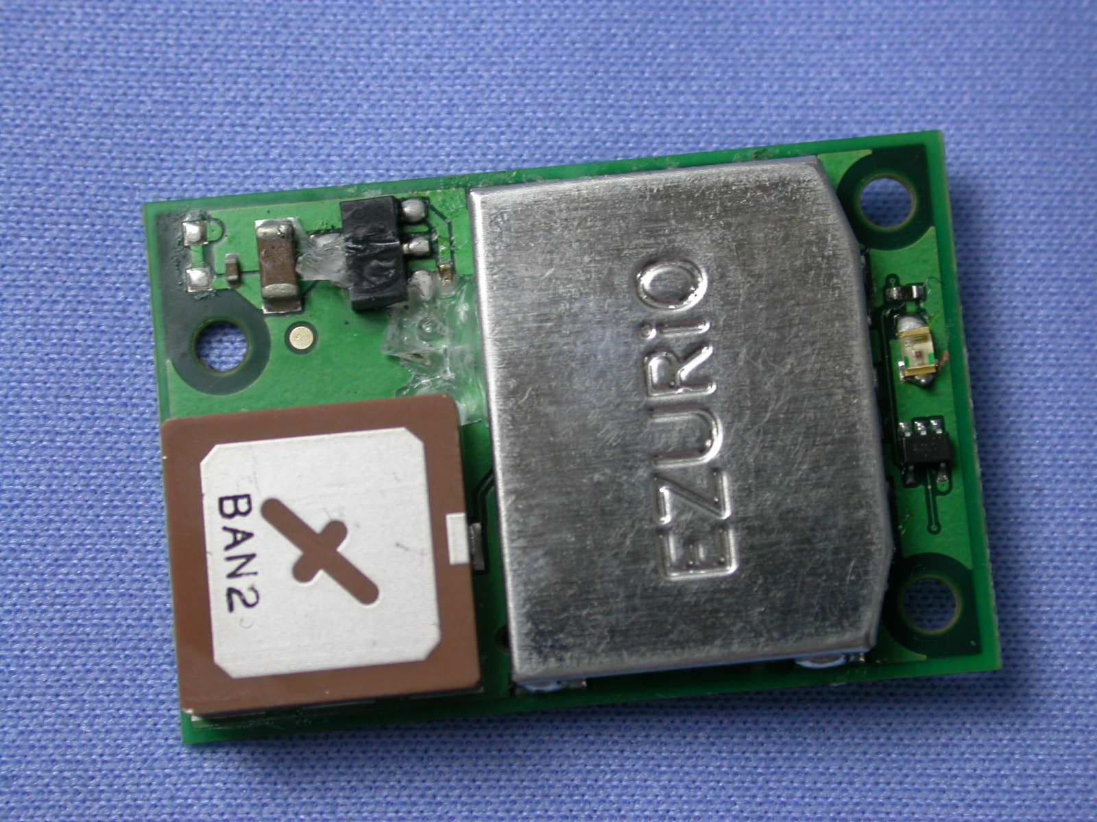
PI407B
Jan 12, 2008Bluetooth Intelligent Serial Module Version II
Equipment Class
DSS - Part 15 Spread Spectrum Transmitter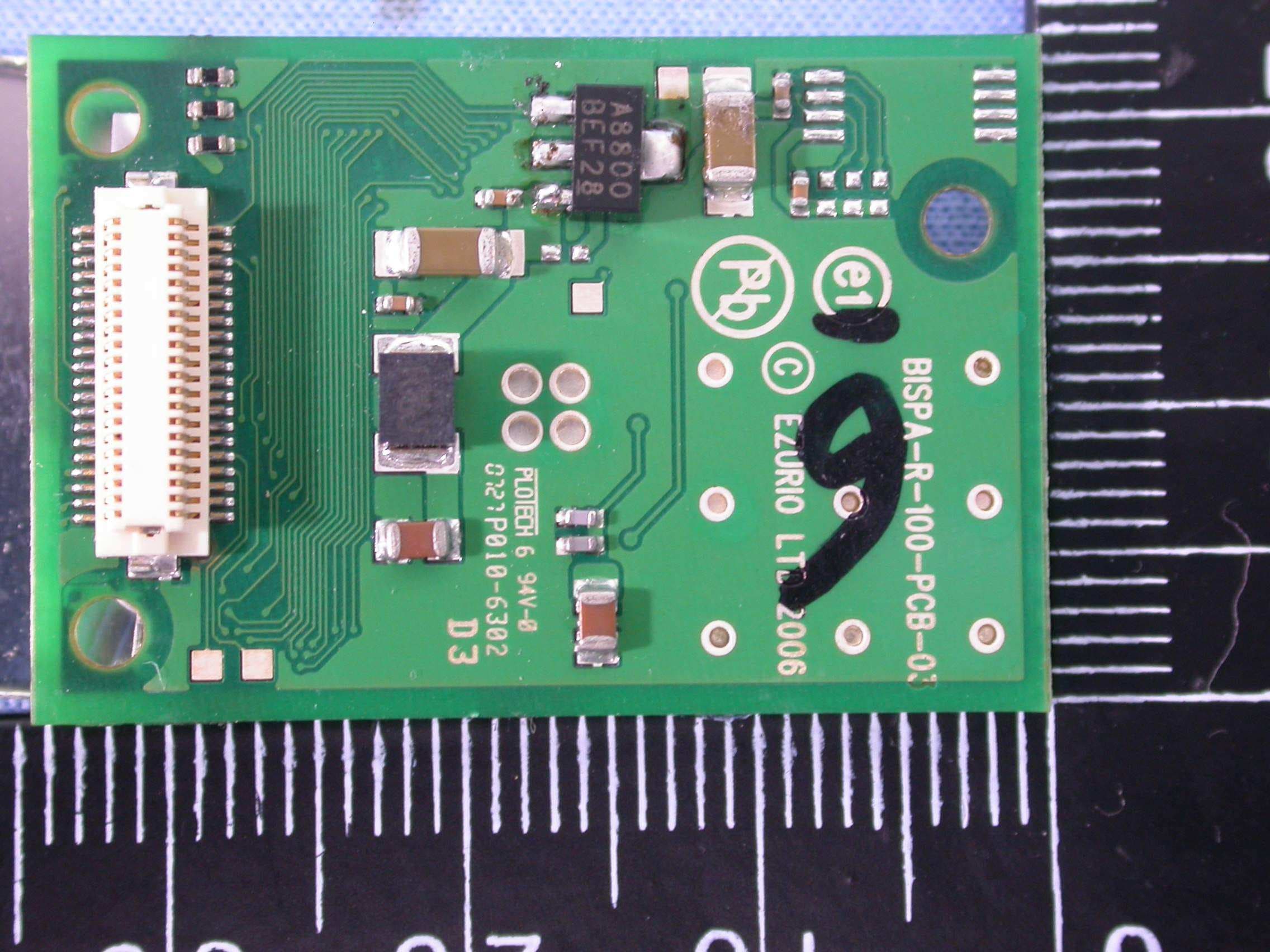
PI409B
Dec 16, 2007BISM PA 3V3
Equipment Class
DSS - Part 15 Spread Spectrum Transmitter