PI4BT-IBM-PCII-1Bluetooth PCMCIA Caard
Laird Connectivity, LLC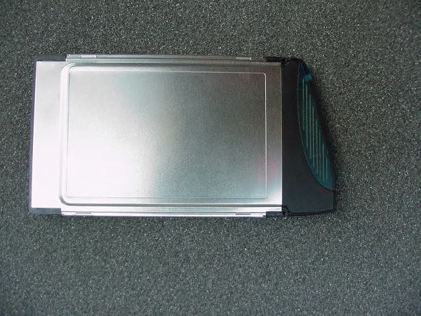
Click to zoom
Application Details
- Equipment Class
- DSS - Part 15 Spread Spectrum Transmitter
- Date of Grant
- Oct 29, 2001
- Application Purpose
- Original Equipment
- Date of Application
- Oct 29, 2001
- Equipment Note
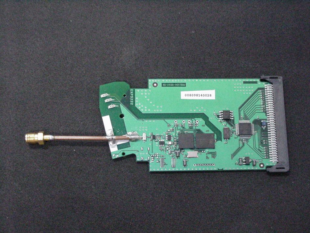
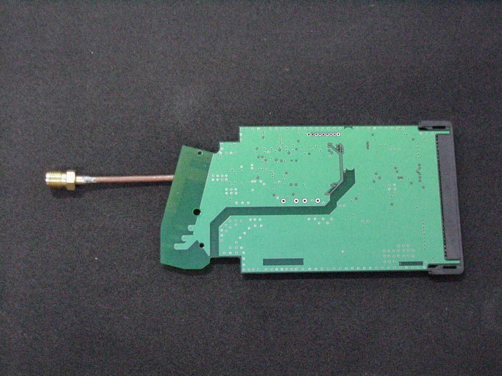
- Bluetooth PCMCIA Caard
- Frequency Range
- 2402.00000000 - 2480.00000000
- Company
- Laird Connectivity, LLC
- Country
- United States
Documents & Files
Document Text
Text extracted from the exhibit documents filed with the FCC. Open a document above to read the original.
Users Manual
1 About your Bluetooth PC Card II from IBM This section contains the product description, hardware and software installation instructions, and operating information for the Bluetooth PC Card II from IBM. Product description Based on the Bluetooth industry standard for wireless communica- tions, the Bluetooth PC Card II from IBM provides computing pro- fessionals with short-range wireless connectivity. You can now use the Bluetooth PC Card II from IBM to make wire- less connections within a personal area network to electronically exchange data and connect your computer to other Bluetooth devices. Some of the key product attributes of the Bluetooth PC Card II from IBM from IBM are as follows: •Any computer supporting a PCMCIA interface •Operation within the 2.4 GHz ISM unlicensed radio spectrum •Maximum data transfer rate of 721 KBps •Range of up to 10 meters (30 feet) •Data-transfer support •Point-to-point or point-multipoint radio link •Low power consumption •Authentication and encryption support •Certified Bluetooth Interoperability by the Bluetooth Special Interest Group •16 bit PCMCIA interface © Copyright IBM Corp. 2001 2 Profiles and services supported by the Bluetooth PC Card II from IBM The following is a list of profiles and services that the PC Card II from IBM supports: •Generic Serial - Establishes a Bluetooth wireless connection between your computer and another Bluetooth-enabled device and uses a temporary serial-port connection. •LAN Access Using PPP - Establishes a Bluetooth wireless net- work connection between your computer and another Bluetooth- enabled device or to a LAN that is connected to the server. •Dialup Networking - Establishes a Bluetooth wireless connection from your computer to a modem or another Bluetooth-enabled device. • OBEX (Object Exchange) Object Push - Establishes a Bluetooth wireless connection that enables your computer to send items from its personal information manager (PIM) to the personal information manager on another Bluetooth-enabled device. •OBEX File Transfer -Establishes a Bluetooth wireless connec- tion that enables your computer to perform file -system actions on another Bluetooth-enabled device. •Fax - Makes a connection available to fax documents from one Bluetooth-enabled device to another. •OBEX IrMC Sync - Establishes a Bluetooth wireless connection and synchronizes the contacts on your computer with the con- tacts on another Bluetooth-enabled device. © Copyright IBM Corp. 2001 3 Installing the Bluetooth PC Card II from IBM This section contains information about making sure that your com- puter has the correct level of BIOS code and installing the Bluetooth PC Card II hardware and software. Verifying the BIOS code level in a ThinkPad computer If you have one of the ThinkPad A, T, or X Series computers that are listed in the tables in this section, your computer must have the required BIOS code level for the Bluetooth PC Card II to work. The ThinkPad BIOS Update Utility is provided on the installation CD. Note: IBM frequently updates the BIOS code: therefore, this infor- mation is subject to change. To download the latest version of the BIOS code for your computer, go to http://www.pc.ibm.com/support on the World Wide Web. Table 2-1. ThinkPad computer BIOS code levels - United States models ThinkPad model Folder name on CD Bios version T20BIOS\TPT20\US x.xx (IYETxxWW) T21BIOS\TPT21\US x.xx (KZETxxWW) T22 BIOS\TPT22\US x.xx (16ETxxWW) A20pBIOS\TPA20p\US x.xx (IVETxxWW) A21p/A22BIOS\TPA21p\US x.xx (KYETxxWW) X20/X21/i Series1620BIOS\TPX20\US x.xx (IZETxxWW) 4 Table 2-2. ThinkPad computer BIOS code levels - Japan models How to check your computers BIOS level To determine the BIOS code level in your ThinkPad computer using the Windows 98SE, Windows 2000, or Windows Me operating sys- tem, use this procedure: 1. Click Start --> Control Panel. Note: For Windows Me, you might have to click View all Control Panel Options. 2. Double click-->the ThinkPad Configuration icon. 3. Click System Information. 4. BIOS Version. 5. Determine whether your BIOS version is older than the BIOS ver- sion listed in the tables: •If your BIOS version is newer than the one listed in Table 2 con- tinue with “ Installing the Bluetooth software”. •If your BIOS version is older than the one listed on Table 2, con- tinue with the next section “ Updating the BIOS code in a Think- Pad computer”. ThinkPad model Folder name on CD Bios version T20BIOS\TPT20\JP x.xx (IYETxxWW) T21BIOS\TPT21\JP x.xx (KZETxxWW) T22 BIOS\TPT22\JP x.xx (16ETxxWW) A20pBIOS\TPA20p\JP x.xx (IVETxxWW) A21p/A22BIOS\TPA21p\JP x.xx (KYETxxWW) X20/X21/i Series1620BIOS\TPX20\JP x.xx (IZETxxWW) 5 • If you are not sure what BIOS version you have continue with the next section “ Updating the BIOS code in a ThinkPad com- puter” and the IBM BIOS Update Utility will check your BIOS version for you. Updating the BIOS code in a ThinkPad computer Your computer must have an ac adapter and a charged battery pack to update the BIOS code. If your ThinkPad computer is attached to any type of port replicator, turn off the computer, and detach the port rep- licator. Before using the IBM ThinkPad BIOS Update Utility with Windows 98SE, download and apply the Windows 98SE Shutdown Supple- ment from the Microsoft support Web site at http://sup- port.microsoft.com/support/kb/articles/Q239/8/87.ASP. To update the BIOS code, use the following procedure: 1. Connect the ac adapter to the ThinkPad computer. 2. Start Windows 98SE, Windows 2000, or Windows Me. 3. Create a temporary folder on your hard drive (for example, c:\temp). 4. Insert the IBM Bluetooth UltraPort Installation CD into your CD- ROM or DVD drive. 5. Refer to the tables on 2-1 to determine the location of the IBM ThinkPad BIOS Update Utility program required to update the BIOS level for your Thinkpad A, T, or X Series computer. 6. Copy the IBM ThinkPad BIOS Update Utility from the appropriate folder on the installation CD and store the file into the temporary f…
Text truncated - open the document above for the full version.
Cover Letter(s)
126 Colindale Avenue Colindale London NW9 5HD United Kingdom Registered in England No. 2348741 Registered Office: 660 Eskdale Road, WINNERSH TRIANGLE, Nr. Wokingham, Berkshire RG41 5TS attn:Reviewing Engineer Federal Communications Commission 7435 Oakland Mills Road Columbia, MD 21046 RE: CONFIDENTIALITY REQUEST FOR THE BLUETOOTH PC CARD II FROM IBM, FCC ID: PI4BT-IBM-PCII-1 To Whom It May Concern: This letter serves as an official request for confidentiality under FCC Rule Section 0.459. We have requested that the schematic diagrams, the layouts and the block diagram required to be submitted with this application be withheld from public review. These documents are company proprietary information that should not get into the possession of competitors. Please contact me if there is any information you may need. Sincerely, Peter de Witdate:22 October 2001 Approvals Manager
ID Label/Location Info
Rear label design for Bluetooth PCB Card for IBM Proposed rear label design for IBM PC Card, using a standard design. Label size will be 42mm*65.5mm Black section will be pre-printed label with white text for approval markings Not pre-printed This section will include serial number, BD Mac address in barcode format Not pre-printed Will change depending on country of manufacture 11 S barcode
Operational Description
3. Testobject Data Type Designation: Kind of Device: (optional) Voltage Type: Voltage level: Equipment under Test: Bluetooth transceiver PCMCIA card Bluetooth PC card II from IBM DC 5.0 V Ports 3.1 General EUT Description General product description: Bluetooth is a short-range radio link intended to be a cable replacement between portable and/or fixed electronic devices. Bluetooth operates in the unlicensed ISM Band at 2.4 GHz. In the US a band of 83.5 MHz width is available. In this band, 79 RF channels spaced 1MHz apart are defined. The channel is represented by a pseudo-random hopping sequence through the 79 channels. The channel is devided into time slots, with a nominal slot length of 625μs, where each slot corresponds to different RF hop frequencies. The nominal hop rate is 1600 hops/s. All frequencies are equally used. The average time of occupancy is 0.3797 s within a 30 second period. The symbol rate on the channel is 1 Ms/s. The EUT provides the following ports: AC line of the laptop Enclosure The main components of EUT are listed and described in Chapter 3.2 Page 7 of 20 Testreport Reference: 4_TDK_0300_BT_FCCb Short Description Equipment under Test Type Designation 3.2 EUT Main components: Type, S/N, Short Descriptions etc. used in this Test Report HW StatusSW StatusSerial No.Date of Receipt Rev3Beta10.305028a980080--Bluetooth PC card II from IBM EUT A NOTE: The short description is used to simplify the identification of the EUT in this test report 3.3 Ancillary Equipment Short Description Equipment under TestType DesignationHW StatusSW StatusSerial No.FCC Id For the purposes of this test report, ancillary equipment is defined as equipment which is used in conjunction with the EUT to provide additional operational and control features to the EUT. It is necessary to configure the system in a typical fashion, as a customer would normally use it. AE 5PC MouseLogitech M- MD15L ---DZLMMD15L AE 4PrinterHP DJ 895 cxi--SG97E1V0Y5- AE 3KeyboardCompaq--123755-002AQ6-23K15 AE 2MonitorSamsung Sync Master 700p --SE 17H3MK3052 56N CSE 7839 AE 1LaptopIBM Thinkpad--ZZ-00013- Setup No.Combination of EUTsDescription 3.4 EUT Setups This chapter describes the combination of EUT's and ancillary equipment used for testing. setup 1EUT A + AE 1 + AE 2 + AE 3 + AE 4 + AE 5 Page 8 of 20Testreport Reference: 4_TDK_0300_BT_FCCb
Test Report
Page 1 of 11 PG Results 23 March 2001 Filename: BlueCore01_BC01b_PG_Results_v2.1 MEMORANDUM Distribution:Peter Flittner, Robert Young, James Collier cc: Prepared By:Alex Busteed Subject:Results of Processing Gain Tests for FCC Qualification 1 INTRODUCTION This memo presents the results of the Processing Gain (PG) tests carried out for FCC qualification of the Cambridge Silicon Radio BC01B Bluetooth chip. The FCC states that the PG from a hybrid Bluetooth receiver must be greater than 17 dB when measured in accordance with the Continuous Wave (CW) jamming margin method. Testing of the BC01b has found the PG due to the DS section to be approximately 5 dB and the PG due to the FH part to be approximately 15 dB. It is therefore concluded that the BC01B complies with the FCC PG requirements for radio communication systems. The rest of this paper outlines the PG measurement technique and discusses the test results. Appendix A contains a list of test equipment and Appendix B contains a printout of the measurement results. 2 METHOD 2.1 PG Definition The Processing Gain from a frequency hopping communication system is derived from two parts, the FH section and the DS section. The PG due to FH is given by a simple equation and is constant. However measurement of the PG due to DS is a little more complex. One technique is to use the CW jamming margin method. This method measures PG due to DS using the following algorithm: A CW signal generator is stepped in 50kHz increments across the passband of the system, recording at each point the generator level required to produce the 0.1% Packet Error Rate (PER). This is the jammer level. This level is then referenced to the output power of the intended Bluetooth signal and the Jammer to Signal Ratio JSR is thus calculated. The worst 4 Page 2 of 11 PG Results 23 March 2001 JSR measurements are discarded and the worst remaining JSR is used to calculate the PG due to DS as follows: sysp LJSRSNRG++= min where G p = the processing gain of the system, SNR = the signal to noise ratio required for 0.1% BER, JSR min = minimum J/S ratio and L sys = system losses. 2.2 PG Measurement Technique Figure 1 provides an overview of the PG measurement technique. The measurement is performed in two parts, measurement of the system SNR and measurement of JSR min . Figure 1: PG Measurement Technique The system SNR is calculated using the following algorithm. Generate Bluetooth PRBS-9 packets using a BC01B emulator (1) and a Vector Signal Generator (2). Combine this signal with white noise of a constant level, which is generated using a noise source (4) and a CW Signal Generator (3). Then vary the level of the Bluetooth signal until the BER measured by the BC01B (7) is 0.1%. The resulting SNR is the signal level divided by the Noise level. Page 3 of 11 PG Results 23 March 2001 The JSR for a given jamming frequency is calculated using the following algorithm. Generate Bluetooth PRBS-9 packets using the BC01B emulator (1) and the Vector Signal Generator (2). Combine this signal with a constant CW tone at the jamming frequency using a CW Signal Generator (5) and a combiner (6). Then vary the level of the Bluetooth signal until the PER measured by the Casira Bluetooth Module (7) is 0.1%. The resulting JSR is the signal level divided by the jamming level. 3 RESULTS 3.1 Overview The measurements found that the PG due to DS caused by the access code in page and inquiry mode is found to be approximately 5dB when the access code is a relatively random mixture of 1's and 0's. A random access code causes the most Inter Symbol Interference (ISI) and hence the worst PG for a hybrid system. Therefore only the results for this access code are used in the PG calculation. The PG due to FH is given as PG FH = 10 log 10 (number of frequency hops) The number of hops in a Bluetooth system is 32, therefore the PG due to FH is approximately 15 dB. When this is added to the PG due to DS, the total PG for the BC01B is approximately 20 dB, above the minimum PG requirement for FCC qualification. 3.2 Detailed Results Test Date:17/11/00 Sample Time: 30 seconds Access Code: c6967e Signal Frequency:2.432GHz Receiver Sensitivity: -88.7 dBm Jammer Signal Level:-85.7 dBm Measured SNR: 18.8dB System Losses: 2dB To calculate processing gain, ignore the worst 20% of data points and then apply the following formula: Page 4 of 11 PG Results 23 March 2001 sysp LJSRSNRG++= min Where G p = Processing Gain of the module SNR = signal to noise ratio of the module JS min = minimum J/S ratio after the worst 20% of J/S samples have been discarded L sys = System losses A total of 20 samples were taken by stepping the jamming signal frequency offsets in 50kHz increments over the bandwidth of the receiver. The worst 4 samples were found at –500kHz, -450kHz, -400kHz and 500kHz and were discarded. The remaining minimum J/S ratio was found to be -15.4dB at an offset of +350kHz Thus, the processing gain due to direct sequence spreading in page and inquiry mode is dBG p 4.524.158.18=+−= -500-400-300-200-1000100200300400500 -30 -25 -20 -15 -10 -5 0 5 Jamming Frequency Offset (kHz) J/S (dBs) J/S ratio performance for Processing Gain FCC Testing Page 5 of 11 PG Results 23 March 2001 APPENDIX A - TEST EQUIPMENT LIST Reference:Instrument TypeName 1BlueCore Emulator BoardN/A 2Vector Signal GeneratorIFR2052 3CW Signal GeneratorIFR2025 4White Noise GeneratorHP33120A 5RF MixerM8HC-7 6RF Combiner6 dB loss combiner 7Bluetooth Motherboard and BC01B Module Casira Development Kit 85V, 4A DC Power SupplyN/A 9Spectrum AnalyserHP E4405B Page 6 of 11 PG Results 23 March 2001 APPENDIX B - TEST RESULTS Timestamp: 14:42.43, 16/11/2000 Signal Freq = 2.432 GHz Jammer Level = -85.7 dBm Jammer Offset = -500 kHz Level = -68.7 dBm BER = 0.03% PER = 0.01% SER1 = 0.01% SER2 = 0.01% Level = -70.7 dBm BER = 0.32% PER = 0.79% SER1 = 0.79% SER2 = 0.79% Level = -69.7 dBm BER = 0.11% PER = 0.18% SER1 = 0.18% SER2 = 0.18% Level = -68.7 dBm BER = 0.04% PER = 0.03% SER1 …
Text truncated - open the document above for the full version.
Test Report
Registergerichth registered in:Vorstandh Board of Directors:7 layers AG, Borsigstrasse 11 Ratingen HRB 3264Dr. Wolfgang Dahm40880 Ratingen, Germany AufsichtsratsvorsitzendehDr. Hans-Jürgen MeckelburgPhone: +49 (0) 2102 749 0 Chairman of the Supervisory Board:Fax: +49 (0) 2102 749 350 Dr. Sabine Grobeckerwww.7layers.com Annex Additional declaration part according FCC 15.247 for Bluetooth devices Version: 2000-01-11 (Annex - Additional declaration part according FCC 15.247 for Bluetooth devices) Page 2 of 5 pages 1 Output power and channel separation of a Bluetooth device in the different operating modes: The different operating modes (data-mode, acquisition-mode) of a Bluetooth device don’t influence the output power and the channel spacing. There is only one transmitter which is driven by identical input parameters concerning these two parameters. Only a different hopping sequence will be used. For this reason the check of these RF parameters in one op-mode is sufficient. 2 Frequency range of a Bluetooth device: Hereby we declare that the maximum frequency of this device is: 2402 – 2480 MHz. This is according the Bluetooth Core Specification V 1.0B (+ critical errata) for devices which will be operated in the USA. This was checked during the Bluetooth Qualification tests (Test Case: TRM/CA/04-E). Other frequency ranges ( e.g. for Spain, France, Japan) which are allowed according the Core Specification are not supported by this device. 3 Co-ordination of the hopping sequence in data mode to avoid simultaneous occupancy by multiple transmitters: Bluetooth units which want to communicate with other units must be organised in a structure called piconet. This piconet consist of max. 8 Bluetooth units. One unit is the master the other seven are the slaves. The master co-ordinates frequency occupation in this piconet for all units. As the master hop sequence is derived from it’s BD address which is unique for every Bluetooth device, additional masters intending to establish new piconets will always use different hop sequences. 4 Example of a hopping sequence in data mode: Example of a 79 hopping sequence in data mode: 40, 21, 44, 23, 42, 53, 46, 55, 48, 33, 52, 35, 50, 65, 54, 67, 56, 37, 60, 39, 58, 69, 62, 71, 64, 25, 68, 27, 66, 57, 70, 59, 72, 29, 76, 31, 74, 61, 78, 63, 01, 41, 05, 43, 03, 73, 07, 75, 09, 45, 13, 47, 11, 77, 15, 00, 64, 49, 66, 53, 68, 02, 70, 06, 01, 51, 03, 55, 05, 04 (Annex - Additional declaration part according FCC 15.247 for Bluetooth devices) Page 3 of 5 pages 5 Equally average use of frequencies in data mode and behaviour for short transmissions: The generation of the hopping sequence in connection mode depends essentially on two input values: 1. LAP/UAP of the master of the connection 2. Internal master clock The LAP (lower address part) are the 24 LSB’s of the 48 BD_ADDRESS. The BD_ADDRESS is an unambiguous number of every Bluetooth unit. The UAP (upper address part) are the 24 MSB’s of the 48 BD_ADDRESS. The internal clock of a Bluetooth unit is derived from a free running clock which is never adjusted and is never turned off. For synchronisation with other units only offset are used. It has no relation to the time of the day. Its resolution is at least half the RX/TX slot length of 312.5 μs. The clock has a cycle of about one day (23h30). In most case it is implemented as 28 bit counter. For the deriving of the hopping sequence the entire LAP (24 bits), 4 LSB’s (4 bits) (Input 1) and the 27 MSB’s of the clock (Input 2) are used. With this input values different mathematical procedures (permutations, additions, XOR- operations) are performed to generate the sequence. This will be done at the beginning of every new transmission. Regarding short transmissions the Bluetooth system has the following behaviour: The first connection between the two devices is established, a hopping sequence was generated. For transmitting the wanted data the complete hopping sequence was not used. The connection ended. The second connection will be established. A new hopping sequence is generated. Due to the fact that the Bluetooth clock has a different value, because the period between the two transmission is longer (and it cannot be shorter) than the minimum resolution of the clock (312.5 μs). The hopping sequence will always differ from the first one. 6 Receiver input bandwidth and behaviour for repeated single or multiple packets: The input bandwidth of the receiver is 1 MHz. In every connection one Bluetooth device is the master and the other one is the slave. The master determines the hopping sequence (see chapter 5). The slave follows this sequence. Both devices shift between RX and TX time slot according to the clock of the master. Additionally the type of connection (e.g. single or multislot packet) is set up at the beginning of the connection. The master adapts its hopping frequency and its TX/RX timing according to the packet type of the connection. Also the slave of the connection will use these settings. Repeating of a packet has no influence on the hopping sequence. The hopping sequence generated by the master of the connection will be followed in any case. That means, a repeated packet will not be send on the same frequency, it is send on the next frequency of the hopping sequence. (Annex - Additional declaration part according FCC 15.247 for Bluetooth devices) Page 4 of 5 pages 7 Dwell time in data mode The dwell time of 0.3797s within a 30 second period in data mode is independent from the packet type (packet length). The calculation for a 30 second period is a follows: Dwell time = time slot length * hop rate / number of hopping channels *30s Example for a DH1 packet (with a maximum length of one time slot) Dwell time = 625 μs * 1600 1/s / 79 * 30s = 0.3797s (in a 30s period) For multislot packet the hopping is reduced according to the length of the packet. Example for a DH5 packet (with a maximum length of five time slots) Dwell time = 5 * 625 μs * 1600 * 1/5 *1/s /…
Text truncated - open the document above for the full version.
Test Report
EMC Measurement/Technical Report 4_TDK_0300_BT_FCCc on 7 Layers AG Borsigstr. 11 40880 Ratingen Germany Note: The following test results relate only to the devices specified in this document. This report shall not be reproduced in parts without the written approval of the testing laboratory. Bluetooth PC card II from IBM Registergericht - registered in: Ratingen, HRB 3264 Aufsichtratsvorsitzende - Chairman of the Supervisory Board: Dr. Sabine Grobecker Vorstand - Board of Directors: Dr. Wolfgang Dahm Dr. Hans-Jürgen Meckelburg 7 layers AG, Borsigstrasse 11 40880 Ratingen, Germany Phone: +49 (0) 2102 749 0 Fax: +49 (0) 2102 749 350 http://www.7Layers.com Report Reference: TTI-P-G 178/99TTI-P-G 178/99 Table of Contents 0. Summary 0.1 Technical Report Summary 0.2 Measurement Summary 1. Administrative Data 1.1 Testing Laboratory 1.2 Project Data 1.3 Applicant Data 1.4 Manufacturer Data 3. Testobject Data 3.1 General EUT Description 3.2 EUT Main Components 3.3 Ancillary Equipment 3.4 EUT Setups 3.5 Operating Modes 4. Measurement Results Conducted Emissions Occupied Bandwidth Peak Power Output Spurious RF Conducted Emissions 5. Testequipment 6. Foto Report 7. Setup Drawings 3 3 4 6 6 6 6 6 8 8 9 9 9 10 11 11 13 16 19 30 33 36 37 Spurious RF Radiated Emissions21 2. Product Labeling 2.1 FCC ID Label 2.2 Location of Label on the EUT 7 7 7 Dwell Time Power Density Channel Separation Processing Gain 25 27 29 4.1 4.2 4.3 4.4 4.5 4.6 4.7 4.8 8. Annex Measurement plots27 Pages Page 2 of 61Testreport Reference: 4_TDK_0300_BT_FCCc 0 Summary 0.1 Technical Report Summary Type of Authorization: Certification for an Intentional Radiator (Frequency Hopping Spread Spectrum) Applicable FCC Rules: Prepared in accordance with the requirements of FCC Rules and Regulations as listed in 47 CFR Ch.1 Parts 0 to 19 (10-1-98 Edition). The following subparts are applicable to the results in this test report. Part 2, Subpart J - Equipment Authorization Procedures, Certification Sections Part 15, Subpart C - Intentional Radiators § 15.201 Equipment authorization requirement § 15.207 Conducted limits § 15.209 Radiated emission limits; general requirements § 15.247 Operation within the bands 902-928 MHz, 2400-2483,5 MHZ and 5725-5850 MHz Summary Test Results: The Equipment under test fulfilled the requirements of the applied FCC rules. Note: The tests were selected and performed with reference to the FCC Public Notice DA 00- 705, released March 30, 2000 Page 3 of 61Testreport Reference: 4_TDK_0300_BT_FCCc 0.2 Measurement Summary § 15.207FCC Part 15, Subpart C ANSI C63.41992The measurement was performed according to Conducted Emissions (AC Power Line)Conducted Emissions (AC Power Line) OP-ModeOP-ModeSetupSetupPortPortFinal ResultFinal Result setup 1op-mode 2AC line of the laptoppassed § 15.247 (a) (1) (ii)FCC Part 15, Subpart C ANSI C63.41992The measurement was performed according to Occupied BandwidthOccupied Bandwidth OP-ModeOP-ModeSetupSetupPortPortFinal ResultFinal Result setup 2op-mode 1temporary antenna connectorpassed setup 2op-mode 2temporary antenna connectorpassed setup 2op-mode 3temporary antenna connectorpassed setup 2op-mode 4temporary antenna connectorpassed setup 2op-mode 5temporary antenna connectorpassed § 15.247 (b) (1)FCC Part 15, Subpart C FCC §15.3110-1-1998The measurement was performed according to Peak Power OutputPeak Power Output OP-ModeOP-ModeSetupSetupPortPortFinal ResultFinal Result setup 2op-mode 1temporary antenna connectorpassed setup 2op-mode 2temporary antenna connectorpassed setup 2op-mode 3temporary antenna connectorpassed setup 2op-mode 4temporary antenna connectorpassed setup 2op-mode 5temporary antenna connectorpassed § 15.247 (c)FCC Part 15, Subpart C FCC §15.3110-1-1998The measurement was performed according to Spurious RF Conducted EmissionsSpurious RF Conducted Emissions OP-ModeOP-ModeSetupSetupPortPortFinal ResultFinal Result setup 2op-mode 1temporary antenna connectorpassed setup 2op-mode 2temporary antenna connectorpassed setup 2op-mode 3temporary antenna connectorpassed § 15.247 (c), §15.35 (b), § 15.209FCC Part 15, Subpart C ANSI C63.41992The measurement was performed according to Spurious Radiated EmissionsSpurious Radiated Emissions OP-ModeOP-ModeSetupSetupPortPortFinal ResultFinal Result setup 1op-mode 1enclosurepassed setup 1op-mode 2enclosurepassed setup 1op-mode 3enclosurepassed § 15.247 (g)FCC Part 15, Subpart C Page 4 of 61Testreport Reference: 4_TDK_0300_BT_FCCc FCC §15.3110-1-1998The measurement was performed according to Dwell TimeDwell Time OP-ModeOP-ModeSetupSetupPortPortFinal ResultFinal Result setup 2op-mode 4temporary antenna connectorpassed setup 2op-mode 5temporary antenna connectorpassed § 15.247 (g)FCC Part 15, Subpart C FCC §15.3110-1-1998The measurement was performed according to Power DensityPower Density OP-ModeOP-ModeSetupSetupPortPortFinal ResultFinal Result setup 2op-mode 4temporary antenna connectorpassed setup 2op-mode 5temporary antenna connectorpassed § 15.247 (a) (1)FCC Part 15, Subpart C FCC §15.3110-1-1998The measurement was performed according to Channel SeparationChannel Separation OP-ModeOP-ModeSetupSetupPortPortFinal ResultFinal Result setup 2op-mode 5temporary antenna connectorpassed Responsible for Accreditation Scope: Responsible for Test Report: Page 5 of 61Testreport Reference: 4_TDK_0300_BT_FCCc 1. Administrative Data 1.1 Testing Laboratory Company Name: Address: The test facility is also accredited by the following accreditation organisation: Responsible for Accreditation Scope: 7 Layers AG Borsigstr. 11 40880 Ratingen Germany DAR-Registration no. TTI-P-G 178/99 Dipl.-Ing Bernhard Retka Dipl.-Ing Arndt Stöcker This facility has been fully described in a report submitted to the FCC and accepted in a letter dated February 07, 2000 under the registration number 96716. - Deutscher Akkreditierungs Rat - Regulierungsbehörde für Telekommunikation und Post (Reg TP) 07.08.01 Dipl.- Ing. Thomas Hoell 04.10.01 20.08. - 28.09.01 Responsible for t…
Text truncated - open the document above for the full version.
Test Report
EMC Measurement/Technical Report 4_TDK_0300_BT_FCCd on 7 Layers AG Borsigstr. 11 40880 Ratingen Germany Note: The following test results relate only to the devices specified in this document. This report shall not be reproduced in parts without the written approval of the testing laboratory. Bluetooth PC card II from IBM Registergericht - registered in: Ratingen, HRB 3264 Aufsichtratsvorsitzende - Chairman of the Supervisory Board: Dr. Sabine Grobecker Vorstand - Board of Directors: Dr. Wolfgang Dahm Dr. Hans-Jürgen Meckelburg 7 layers AG, Borsigstrasse 11 40880 Ratingen, Germany Phone: +49 (0) 2102 749 0 Fax: +49 (0) 2102 749 350 http://www.7Layers.com Report Reference: TTI-P-G 178/99TTI-P-G 178/99 Table of Contents 0. Summary 0.1 Technical Report Summary 0.2 Measurement Summary 1. Administrative Data 1.1 Testing Laboratory 1.2 Project Data 1.3 Applicant Data 1.4 Manufacturer Data 3. Testobject Data 3.1 General EUT Description 3.2 EUT Main Components 3.3 Ancillary Equipment 3.4 EUT Setups 3.5 Operating Modes 4. Measurement Results Conducted Emissions Occupied Bandwidth Peak Power Output Spurious RF Conducted Emissions 5. Testequipment 6. Foto Report 7. Setup Drawings 3 3 4 5 5 5 5 5 7 7 8 8 8 9 10 10 15 18 21 Spurious RF Radiated Emissions12 2. Product Labeling 2.1 FCC ID Label 2.2 Location of Label on the EUT 6 6 6 Dwell Time Power Density Channel Separation Processing Gain 4.1 4.5 Page 2 of 21Testreport Reference: 4_TDK_0300_BT_FCCd 0 Summary 0.1 Technical Report Summary Type of Authorization: Certification for an Unintentional Radiator (Class B digital device) Applicable FCC Rules: Prepared in accordance with the requirements of FCC Rules and Regulations as listed in 47 CFR Ch.1 Parts 0 to 19 (10-1-98 Edition). The following subparts are applicable to the results in this test report. Part 2, Subpart J - Equipment Authorization Procedures, Certification Sections Part 15, Subpart B - Unintentional Radiators § 15.101 Equipment authorization requirement § 15.107 Conducted limits § 15.109 Radiated emission limits Summary Test Results: The Equipment under test fulfilled the requirements of the applied FCC rules. Page 3 of 21Testreport Reference: 4_TDK_0300_BT_FCCd 0.2 Measurement Summary §15.107FCC Part 15, Subpart B ANSI C63.41992The measurement was performed according to Conducted Emissions (AC Power Line)Conducted Emissions (AC …
Text truncated - open the document above for the full version.
Contact Information
Applicant
Brian Petted(Technology Leader)
Test Firm
7layers AGRobert Machulec
Technical Specifications
| # | Rule Parts | Frequency Range | Power Output |
|---|---|---|---|
| 1 | 15C | 2.40 GHz - 2.48 GHz | 5.00 mW |
Other Applications from Laird Connectivity, LLC
PI4BL600T
Apr 18, 2013BL600 Series Bluetooth Low Energy Module
Equipment Class
DTS - Digital Transmission System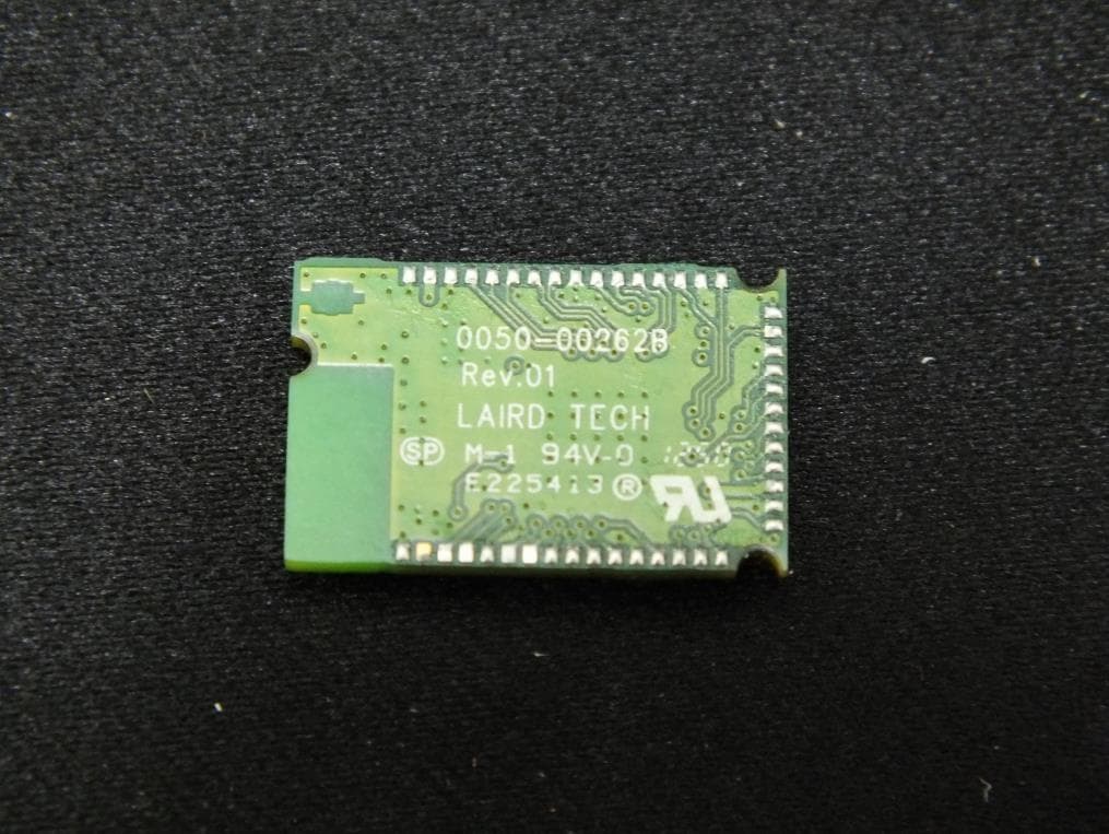
PI4BL600
Apr 11, 2013BL600 Series Bluetooth Low Energy Module
Equipment Class
DTS - Digital Transmission System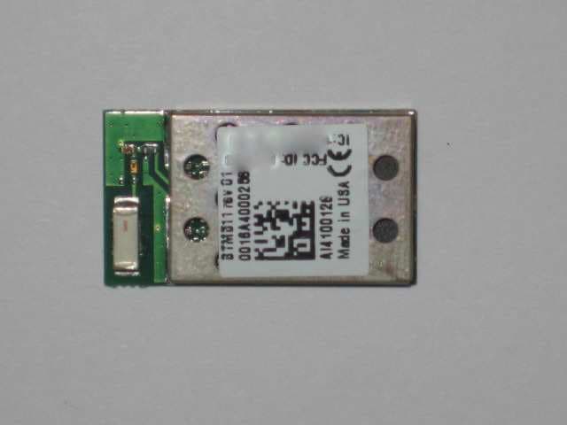
PI4511B
Dec 17, 2009Bluetooth Multimedia Module
Equipment Class
DSS - Part 15 Spread Spectrum Transmitter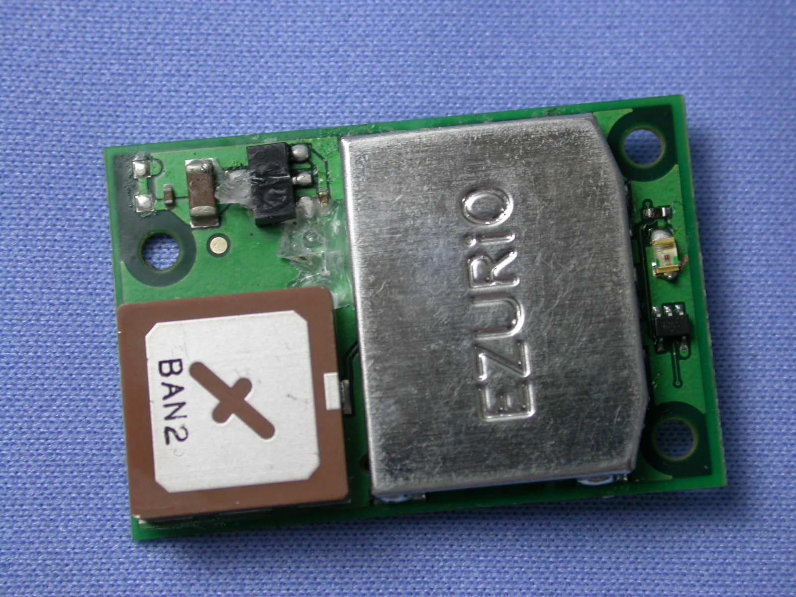
PI407B
Jan 12, 2008Bluetooth Intelligent Serial Module Version II
Equipment Class
DSS - Part 15 Spread Spectrum Transmitter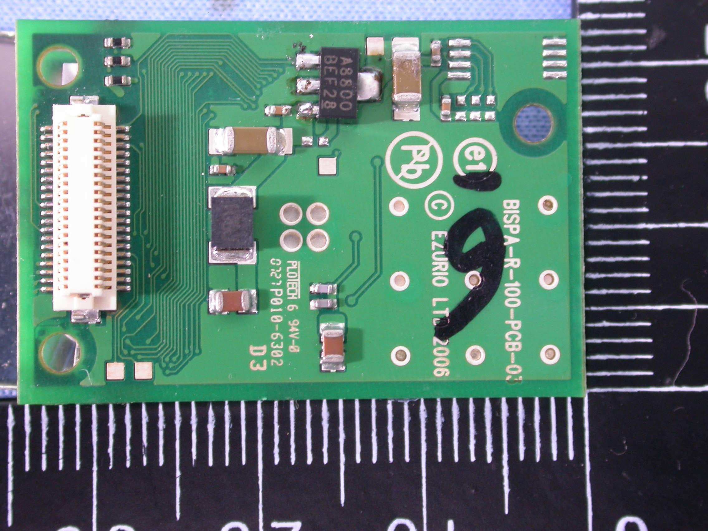
PI409B
Dec 16, 2007BISM PA 3V3
Equipment Class
DSS - Part 15 Spread Spectrum Transmitter