PI4BT-ULTRAUSB Bluetooth Transmitter
Laird Connectivity, LLC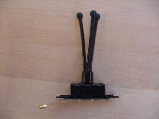
Click to zoom
Application Details
- Equipment Class
- DSS - Part 15 Spread Spectrum Transmitter
- Date of Grant
- May 21, 2001
- Application Purpose
- Original Equipment
- Date of Application
- May 21, 2001
- Equipment Note
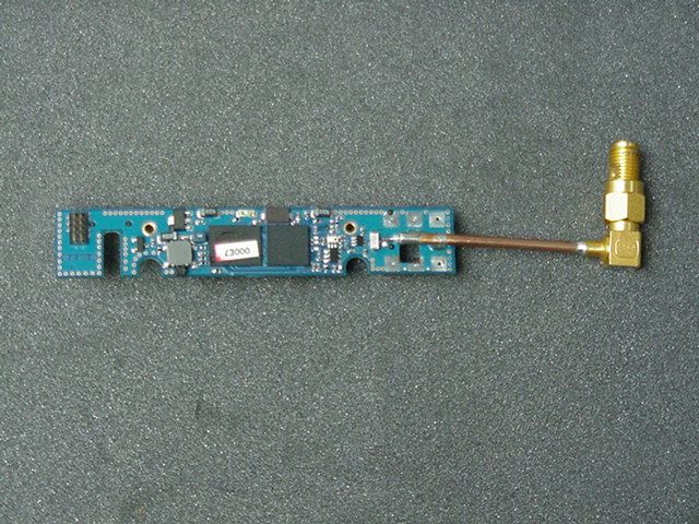
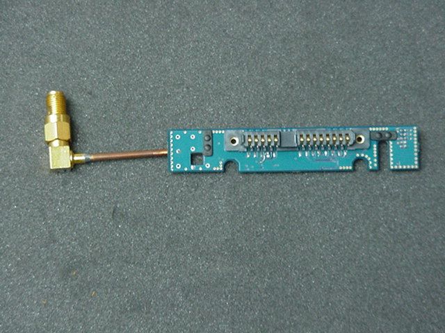
- USB Bluetooth Transmitter
- Frequency Range
- 2402.00000000 - 2480.00000000
- Company
- Laird Connectivity, LLC
- Country
- United States
Documents & Files
Document Text
Text extracted from the exhibit documents filed with the FCC. Open a document above to read the original.
Users Manual
IBM ® Bluetooth UltraPort Module from IBM User’s Reference Guide OPTIONS by IBM First Edition (February 2001) The following paragraph does not apply to the United Kingdom of any country where such provisions are inconsistent with local law: INTERNATIONAL BUSINESS MACHINES CORPORATION PROVIDES THIS PUBLICATION "AS IS" WITHOUT ANY WAR- RANTY OF ANY KIND, EITHER EXPRESS OR IMPLIED, INCLUDING, BUT NOT LIMITED TO, THE LIMITED WAR- RANTIES OF MERCHANTABILITY OF FITNESS FOR A PAR- TICULAR PURPOSE. Some states do not allow disclaimers or express or implied warranties in certain transactions; therefore, this statement may not apply to you. This publication could include technical or typographical errors. Changes are periodically made to the information herein; these changes will be incorporated in new editions of the publication. IBM may make improvements or changes in the products or the programs described in this publication at any time. It is possible that this publication may contain reference to, or infor- mation about, IBM products (machines and programs), programming, or services that are not announced in your country. Such references or information must not be construed to mean that IBM intends to announce such IBM products, programming, or services in your country. Requests for technical information about IBM products should be made to your IBM authorized dealer or your IBM marketing repre- sentative. © Copyright International Business Machines Corporation 2001. All rights reserved. Note to U.S. Government users - Documentation related to restricted rights - Use, duplication or disclosure is subject to restrictions set forth in GSA ADP Schedule Contract with IBM Corp. Contents About the Bluetooth UltraPort Module from IBM Registering your product About the Product Parts and Parts Numbers Hardware, Software, and OS requirements Computers that need an external USB connector Installation Procedure Safety Warnings Safety Statements Physical Installation of the Module Step 1 - Physical Installation of the interposer and the mod- ule.fmPhysical Installation on laptops with a bay Physical Installation on laptops wihtout a bay and on desktop com- puters Physical Installation on X20 Series Installation of the module’s clip-on cover Installation of the Drivers Installation of the software on a laptop Installation of the software on a desktop Updating the system BIOS Installation of the Applications Installation the applications on laptops Installation the applications on desktops Using IBM Ultraport Bluetooth Hints and Tips Working with the Bluetooth Ultraport Module’s Applications The Bluetooth Ultraport Module’s Control Panel Getting Help How to open the software online user’s guide In Addition Appendix A. Help and Service Information Appendix B. Product Warranties Copyright IBM Corp. 2000 Registering Your Product Thank you for purchasing the Bluetooth UltraPort Module from IBM. Please take a few moments to register your product and provide us with information that will help IBM to better serve you in the future. Your feedback is valuable to us in developing products and services that are important to you, as well as in developing better ways to communicate with you. Register your product on the IBM site at: http://www.ibm.com/pc/register IBM will send you information and updates on your registered prod- uct unless you indicate on the Web site questionnaire that you do not want to receive further information. © Copyright IBM Corp. 2001 About the Product The Bluetooth UltraPort Module from IBM (sometimes referred as USB device) is a device allowing your ThinkPad to communicate with other devices without the use of a cable. It is fast becoming a must-have communication tool. The Bluetooth UltraPort Module from IBM is “Plug & Play” compat- ible, which makes installation simple. If you are using a supported IBM ThinkPad, the IBM UltraPort Blue- tooth is configured automatically when you connect it to you com- puter. In addition you will need to use a USB cable to connect your ThinkPad to the Bluetooth UltraPort Module from IBM. These extra parts are provided with the product. Using the Bluetooth UltraPort Module from IBM and the accompa- nying software, you can spice up your communication needs and be synchronized all the time when on the move. 1/ The list of laptops supported is as follows: ThinkPad T20/T21/T22 ThinkPad A20/A21 ThinkPad X20/X21 Thinkpad TransNote ThinkPad i Series ThinkPad 600/E/X ThinkPad 570/E © Copyright IBM Corp. 2001 ThinkPad 390E/X ThinkPad 240/X/Z Note: Some of these laptop have an UltraPort connector, other don't have an UltraPort connector and need to be attached through the external USB connector. 2/ The list of desktops supported is as follows: NetVista A60 NetVista A60i NetVista A40 NetVista A40i NetVista X40i NetVista A40/p NetVista S40/p NetVista X40 NetVista A20 NetVista A20i All of the desktop systems will be connected via the external USB connector. Parts and Parts Numbers When you open the box containing the Bluetooth UltraPort Module from IBM, you can see the following content: •The IBM Ultraport Bluetooth module (USB module) •The IBM system BIOS update CD • The Bluetooth Ultraport CD •A parts kit including: •A USB cable • Interposers (2) •Spacers (2, for X20 Series ThinkPad systems) • The clip-on cover for IBM Ultraport Bluetooth •A tripod • A tripod housing unit Please not that for each part you have a FRU part number and an IBM part number. Find these part numbers below: Part NameFRU NumberIBM Part Number Adapter ASM08K6108 Bluetooth UltraPort Module 09N9813 Here are some of them: The numbers on the left are IBM FRU part numbers with descriptions etc. 04P3072 Interposers and cover FRU 27L0542 USB CABLE FRU 08K6108 Adapter ASM FRU 08K6449 Tripod FRU 09N9813 Bluetooth UltraPort FRU Module 22P4907 Bluetooth UltraPort Sydney Spacers FRU Bob. let me know if this is unclear. Note: You need the USB only if you use a desktop computer or one of the following laptops: T…
Text truncated - open the document above for the full version.
Users Manual
Safety Warnings Please make sure you read the following points before you start using your Bluetooth UltraPort Module: Only avoid using it in airplanes and hospitals. If you need to travel with the Bluetooth UltraPort module from IBM and have to go to a hospital or to any place where electronic equipment is used, switch off the unit completely, or remove it. Make sure the your Bluetooth UltraPort Module is kept at a distance of at least 22 cm of a pacemaker. The Bluetooth UltraPort Module may impact the functioning of the pacemaker. As you may not know who has and who hasn't a pacemaker, make sure you have removed the module from your computer whenever you are in a crowd. As a rule make sure you don't use your module when you are close to any electronic equipment. This includes fire detectors, automatic doors, etc. Keep your Bluetooth UltraPort Module at a distance of at least 2m from any *OA, *AV piece of equipment, and at least 3m away from a microwave oven. If you work too close to a TV set or a radio receiver, you may not be able to communicate with other devices and at the same time your Bluetooth equipment may impact the quality of your TV image or the quality of the reception of your radio receiver. Do not detach the UltraPort device while an application is running. Although your ThinkPad computer has two USB ports (the USB port and the UltraPort bay), use only one port at a time for an UltraPort. If your ThinkPad has an UltraPort connector, you can choose either the connector or a USB port. Do not put an operating cellular phone near the computer when using the Ultraport Bluetooth device. It might cause a system malfunction. *Note: OA refers to Office Automation products and AV to Audio Video products. Please note the following: In order to comply with FCC RF Exposure requirements, this device must be installed in such a way that a minimum separation distance of 20 cm is always maintained between the antenna and all persons during normal operation.
ID Label/Location Info
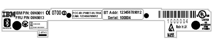
label will be turned 180°
ID Label/Location Info
Marianne Bosley To:[email protected] Cc:Chris Harvey Subject:RE: new TCB application Good morning sir, I have reviewed the attached information for all of the necessary administrative documentation, and have found the following: 1. FCC Label Location - I did not find a photo, or engineer's drawing, of the device showing the location of the FCC label on the device. 2. FCC Identification Label - Where you have the FCC ID, and the format of it, on the "label plate" is fine. However, we either need a revised copy of this label plate showing the correct ID now that you have a grantee code for TDK (no XXXs), or another copy of the same label plate with a statement on the side of that label plate stating that "FCC ID:XXXBT-ULTRA will be replaced with FCC ID:PI4BT-ULTRA". 3. Statement pursuant to Section 15.19 of the FCC Rules and Regs - I did locate this statement in the User's reference guide/manual. However, the FCC's rule is that if the device is larger than your palm, than there is room for this statement on the device (most include it on the identification label). 4. Confidentiality - Should you desire the schematics and block diagram to be held confidential, you must submit a written request. You must specifiy the FCC identifier, the FCC Rule Part that refers to confidentiality, and the items to be held confidential. Please refer to the application package attachment for an example. 5. Manual - Is the User's reference guide the user's manual. 6. Manual user's information - I could not locate the statement pursuant to Section 15.21 of the FCC Rules & Regs in the manual. A copy is attached. 7. Service agreement - A copy is attached. It is policy of the TCB process to have one signed by each manufacturer. Please have TDK sign and return to us. -----Origina l Message----- From:Chris Harvey Sent:Friday, March 09, 2001 9:26 AM To:Marianne Bosley Subject:FW: new TCB application Please associate these documents with the MT#10706. Thanks -----Origina l Message----- From:Lohoff Torsten [SMTP:[email protected]] Sent:Friday, March 09, 2001 5:10 AM To:'Chris Harvey' Subject:AW: new TCB application Chris, attached the file with the TDK documents. We have not yet finished the FCC test reports. This will be done in the next week. You can already start with the administrative review. Thanks I will be out of the office next week until Wednesday (in Moscow for type approval). Best Regards Torsten -----Ursprüngliche Nachricht----- Von: Chris Harvey [mailto:[email protected]] Gesendet am: Donnerstag, 8. März 2001 17:51 An: 'Lohoff Torsten' Betreff: RE: new TCB application Torsten, if you can get the Test Report and Users Manual information to me today, will attempt to get Greg to review them today. Otherwise the technical review may need to wait a few days. Please let me know if this is possible (you can follow up with the administrative paperwork, such as the authorization letters, confidentiality letters, labels, TCB Contract, Schematics, Block Diagrams, etc. tomorrow to complete the application). Best regards, Chris Harvey Chris Harvey EMC Lab Director MET Laboratories, Inc. 1-800-638-6057 [email protected] www.metlabs.com > -----Original Message----- > From:Lohoff Torsten [SMTP:[email protected]] > Sent:Thursday, March 08, 2001 11:30 AM > To:'Chris Harvey' > Subject: AW: new TCB application > > Chris, > > I remember, the grantee fee has increased from 45 to 50. > However thanks for the filing. You will get the whole documents tomorrow. > > Regards > > Torsten > > -----Ursprüngliche Nachricht----- > Von: Chris Harvey [mailto:[email protected]] > Gesendet am: Donnerstag, 8. März 2001 17:23 > An: 'Lohoff Torsten' > Betreff: RE: new TCB application > > Torsten, I have filed for the FCC Grantee Code for TDK. It is PI4, the > second letter is a "capital i". It is already paid for on my credit card, > so there should be no fee issues this time. We are available to file an > application at any time. Please be sure that the documentation submitted, > especially the label, has the Grantee Code included in it. > > I forgot to look-up the grantee code fee (which recently changed). I paid > the $50 fee, but will only invoice to you the $45 fee I mentioned earlier. > A small bonus for you. > > thanks, > > Chris > > Chris Harvey > EMC Lab Director > MET Laboratories, Inc. > 1-800-638-6057 > [email protected] > www.metlabs.com > > > > -----Original Message----- > > From: Lohoff Torsten [SMTP:[email protected]] > > Sent:Thursday, March 08, 2001 10:34 AM > > To:'Chris Harvey' > > Subject:AW: new TCB application > > > > Chris, > > > > the contact information is in my mail below. > > Please let me know the grantee code as soon as you received it. We can > > complete the rest of the documents then. > > > > Thanks > > > > Torsten > > > > -----Ursprüngliche Nachricht----- > > Von: Chris Harvey [mailto:[email protected]] > > Gesendet am: Donnerstag, 8. März 2001 16:31 > > An: 'Lohoff Torsten' > > Cc: Marianne Bosley > > Betreff: RE: new TCB application > > > > Torsten I received the PO this morning for the Grantee Code request and > > TCB > > filing for the new TDK application. Do you need any documentation from > me > > to assist you in gathering the information? In order for MET to request > > the > > Grantee Code we will need the full company name and address for the TDK > > office as well as the phone, fax email and contact information. > > > > Best regards, > > > > Chris Harvey > > > > Chris Harvey > > EMC Lab Director > > MET Laboratories, Inc. > > 1-800-638-6057 > > [email protected] > > www.metlabs.com > > > > > > > > > > > -----Original Message----- > > > From: Lohoff Torsten [SMTP:[email protected]] > > > Sent: Wednesday, March 07, 2001 12:58 PM > > > To:'[email protected]' > > > Subject:new TCB application > > > > > > Chris, > > > > > > I am just preparing the purchase order for the new project, the TDK > > > 'Bluetooth Ultraport Module from IBM' > > > I did not pu…
Text truncated - open the document above for the full version.
Operational Description
Registergerichth registered in:Vorstandh Board of Directors:7 layers AG, Borsigstrasse 11 Ratingen HRB 3264Dr. Wolfgang Dahm40880 Ratingen, Germany AufsichtsratsvorsitzendehDr. Hans-Jürgen MeckelburgPhone: +49 (0) 2102 749 0 Chairman of the Supervisory Board:Fax: +49 (0) 2102 749 350 Dr. Sabine Grobeckerwww.7layers.com Annex Additional declaration part according FCC 15.247 for Bluetooth devices Version: 2000-01-11 (Annex - Additional declaration part according FCC 15.247 for Bluetooth devices) Page 2 of 5 pages 1 Output power and channel separation of a Bluetooth device in the different operating modes: The different operating modes (data-mode, acquisition-mode) of a Bluetooth device don’t influence the output power and the channel spacing. There is only one transmitter which is driven by identical input parameters concerning these two parameters. Only a different hopping sequence will be used. For this reason the check of these RF parameters in one op-mode is sufficient. 2 Frequency range of a Bluetooth device: Hereby we declare that the maximum frequency of this device is: 2402 – 2480 MHz. This is according the Bluetooth Core Specification V 1.0B (+ critical errata) for devices which will be operated in the USA. This was checked during the Bluetooth Qualification tests (Test Case: TRM/CA/04-E). Other frequency ranges ( e.g. for Spain, France, Japan) which are allowed according the Core Specification are not supported by this device. 3 Co-ordination of the hopping sequence in data mode to avoid simultaneous occupancy by multiple transmitters: Bluetooth units which want to communicate with other units must be organised in a structure called piconet. This piconet consist of max. 8 Bluetooth units. One unit is the master the other seven are the slaves. The master co-ordinates frequency occupation in this piconet for all units. As the master hop sequence is derived from it’s BD address which is unique for every Bluetooth device, additional masters intending to establish new piconets will always use different hop sequences. 4 Example of a hopping sequence in data mode: Example of a 79 hopping sequence in data mode: 40, 21, 44, 23, 42, 53, 46, 55, 48, 33, 52, 35, 50, 65, 54, 67, 56, 37, 60, 39, 58, 69, 62, 71, 64, 25, 68, 27, 66, 57, 70, 59, 72, 29, 76, 31, 74, 61, 78, 63, 01, 41, 05, 43, 03, 73, 07, 75, 09, 45, 13, 47, 11, 77, 15, 00, 64, 49, 66, 53, 68, 02, 70, 06, 01, 51, 03, 55, 05, 04 (Annex - Additional declaration part according FCC 15.247 for Bluetooth devices) Page 3 of 5 pages 5 Equally average use of frequencies in data mode and behaviour for short transmissions: The generation of the hopping sequence in connection mode depends essentially on two input values: 1. LAP/UAP of the master of the connection 2. Internal master clock The LAP (lower address part) are the 24 LSB’s of the 48 BD_ADDRESS. The BD_ADDRESS is an unambiguous number of every Bluetooth unit. The UAP (upper address part) are the 24 MSB’s of the 48 BD_ADDRESS. The internal clock of a Bluetooth unit is derived from a free running clock which is never adjusted and is never turned off. For synchronisation with other units only offset are used. It has no relation to the time of the day. Its resolution is at least half the RX/TX slot length of 312.5 μs. The clock has a cycle of about one day (23h30). In most case it is implemented as 28 bit counter. For the deriving of the hopping sequence the entire LAP (24 bits), 4 LSB’s (4 bits) (Input 1) and the 27 MSB’s of the clock (Input 2) are used. With this input values different mathematical procedures (permutations, additions, XOR- operations) are performed to generate the sequence. This will be done at the beginning of every new transmission. Regarding short transmissions the Bluetooth system has the following behaviour: The first connection between the two devices is established, a hopping sequence was generated. For transmitting the wanted data the complete hopping sequence was not used. The connection ended. The second connection will be established. A new hopping sequence is generated. Due to the fact that the Bluetooth clock has a different value, because the period between the two transmission is longer (and it cannot be shorter) than the minimum resolution of the clock (312.5 μs). The hopping sequence will always differ from the first one. 6 Receiver input bandwidth and behaviour for repeated single or multiple packets: The input bandwidth of the receiver is 1 MHz. In every connection one Bluetooth device is the master and the other one is the slave. The master determines the hopping sequence (see chapter 5). The slave follows this sequence. Both devices shift between RX and TX time slot according to the clock of the master. Additionally the type of connection (e.g. single or multislot packet) is set up at the beginning of the connection. The master adapts its hopping frequency and its TX/RX timing according to the packet type of the connection. Also the slave of the connection will use these settings. Repeating of a packet has no influence on the hopping sequence. The hopping sequence generated by the master of the connection will be followed in any case. That means, a repeated packet will not be send on the same frequency, it is send on the next frequency of the hopping sequence. (Annex - Additional declaration part according FCC 15.247 for Bluetooth devices) Page 4 of 5 pages 7 Dwell time in data mode The dwell time of 0.3797s within a 30 second period in data mode is independent from the packet type (packet length). The calculation for a 30 second period is a follows: Dwell time = time slot length * hop rate / number of hopping channels *30s Example for a DH1 packet (with a maximum length of one time slot) Dwell time = 625 μs * 1600 1/s / 79 * 30s = 0.3797s (in a 30s period) For multislot packet the hopping is reduced according to the length of the packet. Example for a DH5 packet (with a maximum length of five time slots) Dwell time = 5 * 625 μs * 1600 * 1/5 *1/s /…
Text truncated - open the document above for the full version.
Operational Description
./2000 Ver.1 TDK Corporation *Note: This document is PRELIMINARY. All specifications are subject to change without notice and are not guaranteed. PRELIMINARY (under development) CERAMIC PATCH ANTENNA FOR BLUETOOTH SAMPLE P/N: CANPB1240 (12x12x4 mm type) [MECHANICAL DIMENSIONS] [ELECTRICAL CHARACTERISTICS] PARAMETERFREQ (MHz)MIN.MAX.UNIT Centre frequency2442MHz Bandwidth85MHz Antenna Gain2400-2485+2dBi Impedance2400-248550ohm Return Loss2400-2485 -6dB Operating temperature-30+85∞C Storage temperature-40+85∞C [RECOMMENDED PCB PATTERN] ./2000 Ver.1 TDK Corporation *Note: This document is PRELIMINARY. All specifications are subject to change without notice and are not guaranteed. PRELIMINARY (under development) [RADIATION PATTERN] • ITEM:CANPB1240 (12x12x4 mm type) • Measurement frequency:2.47 GHz • Standard antenna:Standard dipole (Anritsu) • Tx antenna:Horn (Condor Systems) -25 -25-25 -25 -20 -20-20 -20 -15 -15-15 -15 -10 -10-10 -10 -5 -5-5 -5 0 00 0 5 55 5 0 00 0 45 4545 45 90 9090 90 135 135135 135 -180 -180-180 -180 -135 -135-135 -135 -90 -90-90 -90 -45 -45-45 -45 zx plane zx planezx plane zx plane yz plane yz planeyz plane yz plane dBi dBidBi dBi z y x Note: Tested antenna has been soldered on 40x40 mm 2 PCB. [GAIN & RETURN LOSS] -35 -30 -25 -20 -15 -10 -5 0 5 2.22.32.42.52.62.7 Freq(GHz) Gain(dBi) -35 -30 -25 -20 -15 -10 -5 0 5 Return(dB) yz plane zx plane mid plane max return Note: These characteristics had been measured on z-axis.
Operational Description
© Copyright IBM Corp. 2001 About the Product The Bluetooth UltraPort Module from IBM (sometimes referred as USB device) is a device allowing your ThinkPad to communicate with other devices without the use of a cable. It is fast becoming a must-have communication tool. The Bluetooth UltraPort Module from IBM is “Plug & Play” compat- ible, which makes installation simple. If you are using a supported IBM ThinkPad, the IBM UltraPort Blue- tooth is configured automatically when you connect it to you com- puter. In addition you will need to use a USB cable to connect your ThinkPad to the Bluetooth UltraPort Module from IBM. These extra parts are provided with the product. Using the Bluetooth UltraPort Module from IBM and the accompa- nying software, you can spice up your communication needs and be synchronized all the time when on the move. 1/ The list of laptops supported is as follows: ThinkPad T20/T21/T22 ThinkPad A20/A21 ThinkPad X20/X21 Thinkpad TransNote ThinkPad i Series ThinkPad 600/E/X ThinkPad 570/E © Copyright IBM Corp. 2001 ThinkPad 390E/X ThinkPad 240/X/Z Note: Some of these laptop have an UltraPort connector, other don't have an UltraPort connector and need to be attached through the external USB connector. 2/ The list of desktops supported is as follows: NetVista A60 NetVista A60i NetVista A40 NetVista A40i NetVista X40i NetVista A40/p NetVista S40/p NetVista X40 NetVista A20 NetVista A20i All of the desktop systems will be connected via the external USB connector.
Test Report
EMC Measurement/Technical Report 4_TDK_0200_BT_FCC_a on 7 Layers AG Borsigstr. 11 40880 Ratingen Germany Note: The following test results relate only to the devices specified in this document. This report shall not be reproduced in parts without the written approval of the testing laboratory. Portofino USB Device Registergericht - registered in: Ratingen, HRB 3264 Aufsichtratsvorsitzende - Chairman of the Supervisory Board: Dr. Sabine Grobecker Vorstand - Board of Directors: Dr. Wolfgang Dahm Dr. Hans-Jürgen Meckelburg 7 layers AG, Borsigstrasse 11 40880 Ratingen, Germany Phone: +49 (0) 2102 749 0 Fax: +49 (0) 2102 749 350 http://www.7Layers.com Report Reference: Table of Contents 0. Summary 0.1 Technical Report Summary 0.2 Measurement Summary 1. Administrative Data 1.1 Testing Laboratory 1.2 Project Data 1.3 Applicant Data 1.4 Manufacturer Data 3. Testobject Data 3.1 General EUT Description 3.2 EUT Main Components 3.3 Ancillary Equipment 3.4 EUT Setups 3.5 Operating Modes 4. Measurement Results Conducted Emissions Occupied Bandwidth Output Power Spurious Emissions Conducted 5. Testequipment 6. Foto Report 7. Setup Drawings 3 3 4 6 6 6 6 6 8 8 9 9 9 10 11 - 11 14 17 29 31 33 Spurious Emissions Radiated19 2. Product Labeling 2.1 FCC ID Label 2.2 Location of Label on the EUT 7 7 7 Dwell Time Power Density Channel Separation Processing Gain 24 26 28 - 4.1 4.2 4.3 4.4 4.5 4.6 4.7 8. Annex Page 2 of 57Testreport Reference: 4_TDK_0200_BT_FCC_a 0 Summary 0.1 Technical Report Summary Type of Authorization: Certification for an Intentional Radiator (Frequency Hopping Spread Spectrum) Applicable FCC Rules: Prepared in accordance with the requirements of FCC Rules and Regulations as listed in 47 CFR Ch.1 Parts 0 to 19 (10-1-98 Edition). The following subparts are applicable to the results in this test report. Part 2, Subpart J - Equipment Authorization Procedures, Certification Sections Part 15, Subpart C - Intentional Radiators § 15.201 Equipment authorization requirement § 15.203 Antenna requirements § 15.207 Conducted limits § 15.209 Radiated emission limits; general requirements § 15.247 Operation within the bands 902-928 MHz, 2400-2483,5 MHZ and 5725-5850 MHz Summary Test Results: All performed tests fulfilled the requirements of the applicable FCC rules. Note: The tests were selected and performed with reference to the FCC Public Notice DA 00- 705, released March 30, 2000 Page 3 of 57Testreport Reference: 4_TDK_0200_BT_FCC_a 0.2 Measurement Summary § 15.247 (a) (1) (ii)FCC Part 15, Subpart C ANSI C63.41992The measurement was performed according to Occupied BandwidthOccupied Bandwidth OP-ModeOP-ModeSetupSetupPortPortFinal ResultFinal Result setup 2op-mode 1temporary antenna connectorpassed setup 2op-mode 2temporary antenna connectorpassed setup 2op-mode 3temporary antenna connectorpassed setup 2op-mode 4temporary antenna connectorpassed setup 2op-mode 5temporary antenna connectorpassed § 15.247 (b) (1)FCC Part 15, Subpart C FCC §15.3110-1-1998The measurement was performed according to Peak Power OutputPeak Power Output OP-ModeOP-ModeSetupSetupPortPortFinal ResultFinal Result setup 2op-mode 1temporary antenna connectorpassed setup 2op-mode 2temporary antenna connectorpassed setup 2op-mode 3temporary antenna connectorpassed setup 2op-mode 4temporary antenna connectorpassed setup 2op-mode 5temporary antenna connectorpassed § 15.247 (c)FCC Part 15, Subpart C FCC §15.3110-1-1998The measurement was performed according to Spurious RF Conducted EmissionsSpurious RF Conducted Emissions OP-ModeOP-ModeSetupSetupPortPortFinal ResultFinal Result setup 2op-mode 1temporary antenna connectorpassed setup 2op-mode 2temporary antenna connectorpassed setup 2op-mode 3temporary antenna connectorpassed § 15.247 (c), §15.35 (b), § 15.209FCC Part 15, Subpart C ANSI C63.41992The measurement was performed according to Spurious Radiated EmissionsSpurious Radiated Emissions OP-ModeOP-ModeSetupSetupPortPortFinal ResultFinal Result setup 3op-mode 1enclosurepassed setup 3op-mode 2enclosurepassed setup 3op-mode 3enclosurepassed § 15.247 (g)FCC Part 15, Subpart C FCC §15.3110-1-1998The measurement was performed according to Dwell TimeDwell Time OP-ModeOP-ModeSetupSetupPortPortFinal ResultFinal Result setup 2op-mode 4temporary antenna connectorpassed setup 2op-mode 5temporary antenna connectorpassed § 15.247 (g)FCC Part 15, Subpart C Page 4 of 57Testreport Reference: 4_TDK_0200_BT_FCC_a FCC §15.3110-1-1998The measurement was performed according to Power DensityPower Density OP-ModeOP-ModeSetupSetupPortPortFinal ResultFinal Result setup 2op-mode 4temporary antenna connectorpassed setup 2op-mode 5temporary antenna connectorpassed § 15.247 (a) (1)FCC Part 15, Subpart C FCC §15.3110-1-1998The measurement was performed according to Channel SeparationChannel Separation OP-ModeOP-ModeSetupSetupPortPortFinal ResultFinal Result setup 2op-mode 6temporary antenna connectorpassed Responsible for Accreditation Scope: Responsible for Test Report: Page 5 of 57Testreport Reference: 4_TDK_0200_BT_FCC_a 1. Administrative Data 1.1 Testing Laboratory Company Name: Address: The test facility is also accredited by the following accreditation organisation: Responsible for Accreditation Scope: 7 Layers AG Borsigstr. 11 40880 Ratingen Germany DAR-Registration no. TTI-P-G 178/99-10 Dipl.-Ing Bernhard Retka Dipl.-Ing Arndt Stöcker This facility has been fully described in a report submitted to the FCC and accepted in a letter dated February 07, 2000 under the registration number 96716. - Deutscher Akkreditierungs Rat - Regulierungsbehörde für Telekommunikation und Post (Reg TP) 2000-12-02 Mattias Geier 2001-04-18 2000-12-02 - 2001-04-11 Project Leader: Receipt of EUT: Date of Test(s): Date of Report: 1.2 Project Data TDK Systems Europe UK Peter de Wit, Heiberg 20A, 6936 126 Colindale Avenue Colindale, London NW9 5HD UK TDK Systems Europe UK Peter de Wit, Heiberg 20A, 6936 126 Colindale Avenue Colindale, London NW9 5HD UK 1.4 Manufacturer Data Company Nam…
Text truncated - open the document above for the full version.
Test Report
EMC Measurement/Technical Report 4_TDK_0200_BT_FCC_b on 7 Layers AG Borsigstr. 11 40880 Ratingen Germany Note: The following test results relate only to the devices specified in this document. This report shall not be reproduced in parts without the written approval of the testing laboratory. Portofino USB Device Registergericht - registered in: Ratingen, HRB 3264 Aufsichtratsvorsitzende - Chairman of the Supervisory Board: Dr. Sabine Grobecker Vorstand - Board of Directors: Dr. Wolfgang Dahm Dr. Hans-Jürgen Meckelburg 7 layers AG, Borsigstrasse 11 40880 Ratingen, Germany Phone: +49 (0) 2102 749 0 Fax: +49 (0) 2102 749 350 http://www.7Layers.com Report Reference: Table of Contents 0. Summary 0.1 Technical Report Summary 0.2 Measurement Summary 1. Administrative Data 1.1 Testing Laboratory 1.2 Project Data 1.3 Applicant Data 1.4 Manufacturer Data 3. Testobject Data 3.1 General EUT Description 3.2 EUT Main Components 3.3 Ancillary Equipment 3.4 EUT Setups 3.5 Operating Modes 4. Measurement Results Conducted Emissi…
Text truncated - open the document above for the full version.
Contact Information
Applicant
Brian Petted(Technology Leader)
Test Firm
7layers AGRobert Machulec
Technical Specifications
| # | Rule Parts | Frequency Range | Power Output |
|---|---|---|---|
| 1 | 15C | 2.40 GHz - 2.48 GHz | 1.40 mW |
Other Applications from Laird Connectivity, LLC
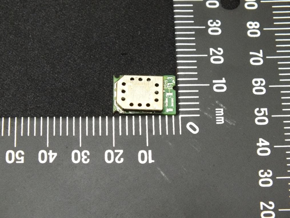
PI4BL600T
Apr 18, 2013BL600 Series Bluetooth Low Energy Module
Equipment Class
DTS - Digital Transmission System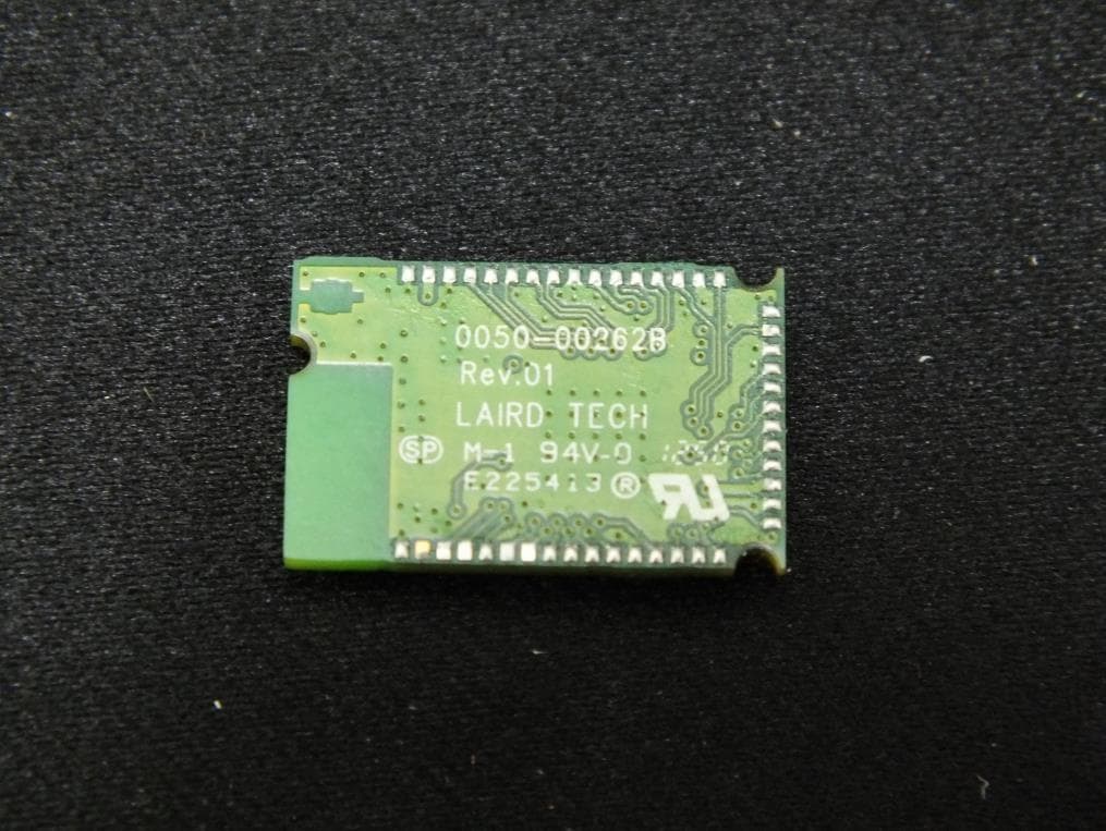
PI4BL600
Apr 11, 2013BL600 Series Bluetooth Low Energy Module
Equipment Class
DTS - Digital Transmission System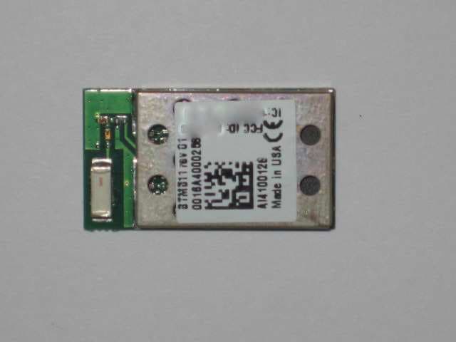
PI4511B
Dec 17, 2009Bluetooth Multimedia Module
Equipment Class
DSS - Part 15 Spread Spectrum Transmitter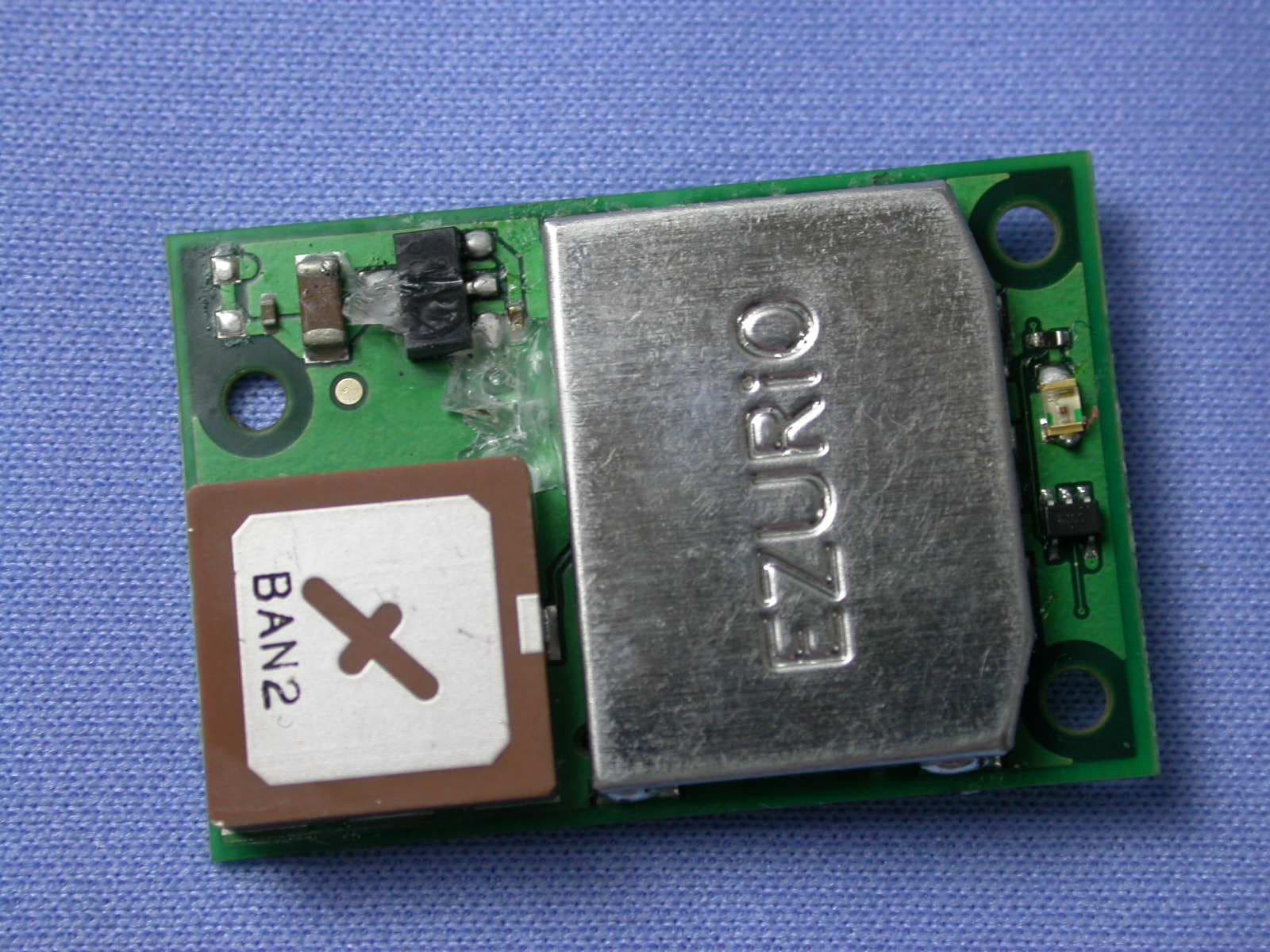
PI407B
Jan 12, 2008Bluetooth Intelligent Serial Module Version II
Equipment Class
DSS - Part 15 Spread Spectrum Transmitter
PI409B
Dec 16, 2007BISM PA 3V3
Equipment Class
DSS - Part 15 Spread Spectrum Transmitter