PIDAIRSPAN-BSR900Base Station Radio (BSR)
Airspan Networks Inc
Click to zoom
Application Details
- Equipment Class
- DTS - Digital Transmission System
- Date of Grant
- Jan 01, 2004
- Application Purpose
- Original Equipment
- Date of Application
- Jan 01, 2004
- Equipment Note
- Base Station Radio (BSR)
- Frequency Range
- 903.00000000 - 927.00000000
- Company
- Airspan Networks Inc
- Country
- United States
Documents & Files
Document Text
Text extracted from the exhibit documents filed with the FCC. Open a document above to read the original.
Users Manual
Connecting the World with Wireless Access Solutions WipLL and AS3010 WipLL and AS3010 WipLL and AS3010 WipLL and AS3010 Systems SystemsSystems Systems Wireless IP-Based Local Loop System Release 4.2B Hardware Installation Guide The WipLL product bears the CE marking. This CE marking demonstrates WipLL's full compliance with applicable European Union (EU) directives: The WipLL product bears the Underwriters Laboratories (UL) marking, demonstrating full compliance with UL's safety requirements: WipLL products also bear the Federal Communications Commission (FCC) marking, demonstrating compliance with FCC Part 15 regulations. Revision Record: WipLL Hardware Installation Guide Pub. Rev. Date Update Description - Nov-00 First edition and printing. (Marconi) - Mar-01 WipLL Release 1.4 (Marconi) - Apr-01 WipLL Release 2.0 (Marconi) - Jul-01 WipLL Release 2.2 (Marconi) - Nov-01 WipLL Release 2.6 (Marconi) - Jun-02 WipLL Release 3.0A (Marconi) 01 Feb-03 WipLL Release 4.0. Author: InterDoc. Updates: Airspan template and content (connector pinouts; cable crimping, and general) 02 May-03 WipLL Release 4.2F. Author: InterDoc. Updates: graphics, deleted BSR with serial port. 03 Jul-03 WipLL Release 4.2A. Author: InterDoc. Updates: Chapter 1 for Transparent Bridging; 5.8 GHz; 2.8 GHz. 04 Aug-03 WipLL Release 4.2A. Author: InterDoc. Updates: formatting; graphics; BSDU LEDs 05 Oct-03 WipLL & AS3010 Rel. 42B. Auth: InterDoc. Updates: RSSI Plug for SPR; IDR RSSI levels; SDA-4S/Vltag; safety guidelines; Append. D. Publication No. 02030311-05 Copyright by Airspan Networks LTD., 2003. All rights reserved worldwide. The information contained in this document is proprietary and is subject to all relevant copyright, patent and other laws protecting intellectual property, as well as any specific agreement protecting Airspan Networks LTD. rights in the aforesaid information. Neither this document nor the information contained herein may be published, reproduced or disclosed to third parties, in whole or in part, without the express, prior, written permission of Airspan Networks LTD. In addition, any use of this document or the information contained herein for any purposes other than those for which it was disclosed is strictly forbidden. Airspan Networks LTD. reserves the right, without prior notice or liability, to make changes in equipment design or specifications. Information supplied by Airspan Networks LTD. is believed to be accurate and reliable. However, no responsibility is assumed by Airspan Networks LTD. for the use thereof nor for the rights of third parties which may be effected in any way by the use thereof. Any representation(s) in this document concerning performance of Airspan Networks LTD. product(s) are for informational purposes only and are not warranties of future performance, either express or implied. Airspan Networks LTD. standard limited warranty, stated in its sales contract or order confirmation form, is the only warranty offered by Airspan Networks LTD. in relation thereto. This document may contain flaws, omissions or typesetting errors; no warranty is granted nor liability assumed in relation thereto unless specifically undertaken in Airspan Networks LTD. sales contract or order confirmation. Information contained herein is periodically updated and changes will be incorporated into subsequent editions. If you have encountered an error, please notify Airspan Networks LTD. All specifications are subject to change without prior notice. Main Operations: Airspan Communications Ltd. Cambridge House Oxford Road Uxbridge Middlesex UB8 1UN United Kingdom Tel: (44)-895 467100 Web site: http//www.airspan.com Customer Service (TAC): [email protected] or (+972) 8 929 2266 This page is intentionally left blank. Hardware Installation Guide Contents 02030311-05 Airspan Networks Ltd. v Contents About this Manual................................................................................................ xiii Purpose ....................................................................................................... xiii Targeted Audience ...................................................................................... xiii Organization of this manual......................................................................... xiv Conventions ................................................................................................. xv Technical support ......................................................................................... xv 1. Introduction .............................................................................................. 1-1 1.1. Main Features ..................................................................................... 1-2 1.2. Customer Benefits............................................................................... 1-3 1.3. System Architecture ............................................................................ 1-4 1.3.1. Base Station ......................................................................... 1-5 1.3.2. Subscriber Site ..................................................................... 1-8 1.3.3. Network Operations Center ................................................ 1-12 1.4. Applications ....................................................................................... 1-13 1.4.1. Broadband Data Access ..................................................... 1-13 1.4.2. High Speed Internet Access ............................................... 1-14 1.4.3. Voice over IP ...................................................................... 1-15 1.4.4. Traffic Engineering in Multi-Tenant Application .................. 1-16 1.4.5. Repeater Solution ............................................................... 1-17 2. Safety Guidelines ..................................................................................... 2-1 2.1. General Safety Guidelines ..........................................…
Text truncated - open the document above for the full version.
Users Manual
Installing the BSDU Hardware Installation Guide 5-10 Airspan Networks Ltd. 02030311-05 Figure 5-5: Cable connections for BSDU daisy chaining Note: When daisy-chaining BSDUs, it does not matter which 100Base-T ports you use to connect two BSDUs. For example, you can connect 100Base-T 1 to 100Base-T 2, or 100Base-T 1 to 100Base-T 1. Hardware Installation Guide Installing the BSDU 02030311-05 Airspan Networks Ltd. 5-11 5.8. Connecting Sync IN/OUT ports The BSDUís front panel provides an in/out synchronization 8-Pin RJ-45 ports for synchronization between BSDUs at the base station. The SYNC OUT of the master BSDU is connected to the SYNC IN of a slave BSDU, which then connects its SYNC OUT to the SYNC IN of another slave BSDU, and so on. ! Connector: 8-Pin RJ-45 (male) ! Cable: straight-through cable ! Connector Pinouts: ! Sync IN Pin Name Description 1 TD+ Transmit data to GPS 2 TD- Transmit data from GPS 3 Rx+ Receive Data (hop synchronization) 4 NC Not connected 5 NC Not connected 6 Rx- Receive Data (hop synchronization) 7 1PPS+ GPS pulse per second 8 1PPS- GPS pulse per second Installing the BSDU Hardware Installation Guide 5-12 Airspan Networks Ltd. 02030311-05 ! Sync OUT Pin Name Description 1 TD+ Transmit data to GPS 2 TD- Transmit data from GPS 3 Tx+ Transmit Data (hop synchronization) 4 RD+ Receive Data (from GPS) 5 RD- Receive Data (to GPS) 6 Tx- Transmit Data (hop synchronization) 7 1PPS+ GPS pulse per second 8 1PPS- GPS pulse per second Hardware Installation Guide Installing the BSDU 02030311-05 Airspan Networks Ltd. 5-13 5.9. Connecting to BSPS for Power Management The BSDUís front panel provides a 9-Pin DB-type port for serial RS-232 power management of the BSPS. WipLLís WipManage manages BSPS by connecting to the BSDU through the IP network (i.e., from the BSR), and then manages BSPS through the serial connection between the BSDU and BSPS. The reason for the serial connection is that the BSPS does not support SNMP-based management, which is the basis of WipManage. ! Connector: depending on the BSPS model: ! 9-Pin D-type female (BSDU and BSPS) -Or- ! 9-Pin D-type female (BSDU) to 8-Pin RJ-45 (BSPS) adapter (see Figure 5-6) Figure 5-6: BSDU-to-BSPS power management connectors (RJ-45 to 9-Pin D-type cable adapter) ! Cable length: 60 cm Installing the BSDU Hardware Installation Guide 5-14 Airspan Networks Ltd. 02030311-05 ! Connector pinouts: BSDU BSPS 9-Pin D-type RJ-45 Pin Name Description Pin Name 1 NC Not connected 1 NC 2 Rx Receive Data 2 NC 3 Tx Transmit Data 3 Rx 4 NC Not connected 4 NC 5 GND Ground 5 GND 6 NC Not connected 6 Tx 7 NC Not connected 7 NC 8 NC Not connected 8 NC 9 NC Not connected To connect the BSDU to the BSPS for BSPS serial power management: 1. Connect the 9-pin D-type female connector, at one end of the cable, to the BSDUís 9-pin D-type port labeled POWER Management (see Figure 5-7). 2. Connect the RJ-45 connector, at the other end of the cable, to the BSPS System Controllerís RJ-45 serial port (see Figure 5-7). Hardware Installation Guide Installing the BSDU 02030311-05 Airspan Networks Ltd. 5-15 Figure 5-7: BSDU-to-BSPS serial cable connections for BSPS power management Installing the BSDU Hardware Installation Guide 5-16 Airspan Networks Ltd. 02030311-05 5.10. Connecting to PC for Serial Management The BSDUís front panel provides a 9-Pin D-type port for BSDU serial management (labeled Monitor). Serial management allows you to connect the WipLLís network management system (WipConfig) to BSDU without assigning BSDU an IP address. ! Connector: 9-pin D-type male ! Cable: straight-through ! Connector pinouts: 9-Pin D-type Connector PinSignal 1 Not connected (NC) 2 Rx 3 Tx 4 NC 5 NC 6 NC 7 NC 8 NC 9 NC Hardware Installation Guide Installing the BSDU 02030311-05 Airspan Networks Ltd. 5-17 To connect the PC to the BSDU by serial connection (see Figure 5-8): 1. Connect the 9-pin D-type female connector to the PC. 2. Connect the 9-pin D-type male connector, at the other end of the cable, to the BSDUís serial port (labeled Monitor). Figure 5-8: PC-to-BSDU Serial Connections Installing the BSDU Hardware Installation Guide 5-18 Airspan Networks Ltd. 02030311-05 5.11. Connecting to PC for Network IP Management For network (IP) configurations, you can connect the PC to the BSDUís local port, or remotely (from anywhere) if you have IP connectivity to the device. For PC-to- BSDU local network (IP) connections you need to connect the PC to the BSDUís 10BaseT or 100BaseT port. The BSDUís front panel provides two 10Base-T ports: left is labeled 10Base-T 1; right is labeled 10Base-T 2. Port 1 provides PC management interface to all BSRs connected to the BSDU. Port 2 provides management interface only to the BSDU. If you connect the BSDUís two 10BaseT ports (i.e., loop the ports) to one another by a crossover cable, then you can connect the PC to one of the BSDUís 100BaseT ports. If the two BSDU 10BaseT ports are not connected to one another, then you need to connect the PC to the BSDUís right- most 10BaseT port (labeled 10Base-T 2). Note: For WipLL management, it is recommended to connect Port 1 to Port 2 by a crossover cable, and then connect the management station (PC) to one of the 100Base-T ports. In such a setup, you can provide management to all daisy-chained BSDUs and their associated BSRs through one 100Base-T port. ! Connector: 8-Pin RJ-45 (male) ! Cables: ! Crossover cable for looping the two 10BaseT ports ! Straight-through for connecting the PC to the 100BaseT port Hardware Installation Guide Installing the BSDU 02030311-05 Airspan Networks Ltd. 5-19 ! Connector pinouts: RJ-45 (10Base-T) RJ-45 (100Base-T) Pin Signal Pin Function 1 +Rx 1+Tx 2 -Rx 2-Tx 3 +Tx 3+Rx 4 NC 4NC 5 NC 5NC 6 -Tx 6-Rx 7 NC 7NC 8 NC 8NC To connect the PC to the BSDU using a network connection: 1. Connect the RJ-45 connector to the PCís Ethernet port. 2. Connector the RJ-45 connector, at the other end of cable, to the BSDUís 10Base-T port labeled 2 (see Figure 5-9); -Or- Connect the BSDUís t…
Text truncated - open the document above for the full version.
Cover Letter(s)
American TCB 6731 Whittier Ave Suite C110 McLean, VA 22101 USA Installaing Outdoor & Indoor units and Third-party External Antennas 1. The device cannot be sold retail,to the general public or by mail order,it must be sold to dealers. 2. Installation must be controlled. 3. Installation must be preformed by licensed professionals. 4. Installation requires special training because a standard N-type connector is used on third- party external antenna. The device is not intended for use by general public, only for industry/commercial use. Name of authorized person: Zion Levi Position: Compliances & Testing Engineer Date: December 31, 2003: Airspan Networks (Israel) Ltd., Israel Address: Harava St,”Unitronics” building Airport City 70100, P.O.199 Israel Tel: +972-3-9777444 ; Fax: +972-3-9777400, www.airspan.com
Cover Letter(s)
HERMON LABORATORIES December 23, 2003 American TCB 6731 Whittier Ave Suite C110 McLean, VA 22101 Attn: Mr. T. Johnson, Examining Engineer RE: your e-mail dated December 12, 2003; Airspan Networks Ltd. FCC ID: PIDAIRSPAN-BSR900, ATCB000959 Dear Mr. Johnson, Please find below the answer to your question. 1) The BSR900_Label.jpg file was uploaded December 23, 2003. 2) For professional installation requirement please refer to page 2-5 of the Installation_Guide_15693. 3) The first antenna connector is for Tx and Rx the same like IDR, one at a time, the second antenna is used in Rx mode for diversity option. 4) The part 2 of complete manual, Hardware_Installation_Guide_v05-42B_part2_1/part2_2 was uploaded on December 23, 2003. 5) The BSR is the base station radio unit and has no provision for connection to personal computer, only gateway or router. The Airspan’s statement was uploaded on December 23, 2003. 6) “Digital_modulation_description” file was uploaded on December 23, 2003 via Additional information folder. 7) Just hybrid mode. 8) Refer to “Digital_modulation_description” file. 9) Refer to “Digital_modulation_description” file. 10) The SA was set in video triggering mode and the trigger position coincides with the left edge of the plot. The Tx duration was verified with longer sweep time to ensure the total Tx duration was captured, but such a plot did not provide sufficient resolution for accurate measurements. 11) The RBW was set 1 MHz, wider than 6 dB BW (refer to plots A15, A19, 6 dB bandwidth is 800 kHz) as required in Federal Register Vol.62 No.92. 12) The testing was performed according to “First example”, page 91, as DTS. 13) Certainly, the calculation on plot A49 was incorrect. The correct value 39.83 dBμV/m is shown in section 4.6, page 12 of the same test report. Sorry for my mistake. 14) The frequency is 4.95 MHz, not 14 MHz, QP and average measurements are demonstrated in section 4.7 of test report and plots A85-A88. Sincerely, Marina Cherniavsky, certification engineer Hermon Laboratories
Cover Letter(s)
HERMON LABORATORIES December 31, 2003 American TCB 6731 Whittier Ave Suite C110 McLean, VA 22101 Attn: Mr. T. Johnson, Examining Engineer RE: your e-mail dated December 31, 2003; Airspan Networks Ltd. FCC ID: PIDAIRSPAN-BSR, ATCB000959 Dear Mr. Johnson, Please find below the answers to your questions. 1) The label with a higher resolution “BSR_900_label_123103” was uploaded on December 31, 2003 via Label Location folder. 2) Aispan confirms that the device operates only in hybrid mode. “Description_Hybrid_mode_900_rev1” page 5 was corrected, the file was uploaded on December 31, 2003 via Operational Description folder. 3) The frequency is 5 MHz not 14 MHz, plot A86 with frequency illustration was uploaded on December 31, 2003 via Additional information folder. 4) The requested letter “Installatiom_marketing_letter” was uploaded on December 31, 2003 via cover letter folders. 5) We regret the information is not clear, we confirm that a) The method “First example” was used, not Method 3; b) “Description_Hybrid_mode_900” is issued for information only, number of hopping channels was not tested and was not compared with the limit – please refer to our test report AIRRAD_FCC.15694_rev1 c) power spectral density was measured and shown - please see §4.1 of our test report AIRRAD_FCC.15694_rev1; d) minimum bandwidth was measured and shown in §4.4 of our test report AIRRAD_FCC.15694_rev1. Sincerely, Marina Cherniavsky, certification engineer Hermon Laboratories
External Photos
FCC ID:PIDAIRSPAN-BSR900 Date: November 2003 Page 1 of 3 EXTERNAL PHOTOGRAPHS This document contains 2 photographs FCC ID:PIDAIRSPAN-BSR900 Date: November 2003 Page 2 of 3 Photograph No.1 BSR 900 MHz base station radio unit Front view FCC ID:PIDAIRSPAN-BSR900 Date: November 2003 Page 3 of 3 Photograph No.2 BSR 900 MHz base station radio unit Rear side view
Operational Description
Technical Note WipLL 900 MHz Wireless IP-Based Local Loop System External Antenna Specifications Connecting the World with Wireless Access Solutions Revision Record: External Antenna Specifications Pub/ Rev Date Update Description 01 Nov-03 Airspan. Author: InterDoc Publication No. 18110311-01 Copyright by Airspan Networks LTD., 2003. All rights reserved worldwide. The information contained in this document is proprietary and is subject to all relevant copyright, patent and other laws protecting intellectual property, as well as any specific agreement protecting Airspan Networks LTD. rights in the aforesaid information. Neither this document nor the information contained herein may be published, reproduced or disclosed to third parties, in whole or in part, without the express, prior, written permission of Airspan Networks LTD. In addition, any use of this document or the information contained herein for any purposes other than those for which it was disclosed is strictly forbidden. Airspan Networks LTD. reserves the right, without prior notice or liability, to make changes in equipment design or specifications. Information supplied by Airspan Networks LTD. is believed to be accurate and reliable. However, no responsibility is assumed by Airspan Networks LTD. for the use thereof nor for the rights of third parties which may be effected in any way by the use thereof. Any representation(s) in this document concerning performance of Airspan Networks LTD. product(s) are for informational purposes only and are not warranties of future performance, either express or implied. Airspan Networks LTD. standard limited warranty, stated in its sales contract or order confirmation form, is the only warranty offered by Airspan Networks LTD. in relation thereto. This document may contain flaws, omissions or typesetting errors; no warranty is granted nor liability assumed in relation thereto unless specifically undertaken in Airspan Networks LTD. sales contract or order confirmation. Information contained herein is periodically updated and changes will be incorporated into subsequent editions. If you have encountered an error, please notify Airspan Networks LTD. All specifications are subject to change without prior notice. External Antenna Specifications Contents 18110311-03 Airspan Networks Ltd. iii Contents 1. Introduction ........................................................................................................................ 4 2. BSR External Antennas ..................................................................................................... 4 2.1. Sector Antenna ...................................................................................................... 5 2.2. Sector Antenna Dual Polarization.......................................................................... 7 2.3. Omnidirectional Antenna ....................................................................................... 9 3. IDR External Antennas..................................................................................................... 10 3.1. 10 dBi Panel ........................................................................................................ 11 3.2. 6.5 dBi Panel ....................................................................................................... 12 External Antenna Specifications Technical Note 18110311-03 Airspan Networks Ltd. 4 1. Introduction The WipLL BSR and IDR devices operating in the 900 MHz band, provide N-type receptacles for connecting external antennas. The BSR provides two N-type receptacles (for antenna diversity), and the IDR provides one TNC-type receptacle. This document lists the specifications of these external antennas intended for the BSR and IDR devices. 2. BSR External Antennas Airspan provides the following external antennas for BSR devices operating in the 900 MHz band: Sector antenna Dual Polarization Sector antenna Omnidirectional antenna External Antenna Specifications Technical Note 18110311-03 Airspan Networks Ltd. 5 2.1. Sector Antenna This antenna is designed for best non-line of sight performance with Airspan’s BSR operating in the 900 MHz band. Advanced features include: high gain and mechanical downtilt. External Antenna Specifications Technical Note 18110311-03 Airspan Networks Ltd. 6 Electrical specifications Frequency range 870 –960 MHz Polarization Vertical Gain 15.5 dBi Half-power beam width • H-plane:65° • E-plane:13° Front-to-back ratio >25 dB Impedance 50 . VSWR <1.3 Intermodulation IM3 (2 x 43 dBm carrier) <–150 dBc Max.power 500 W (at 50 °C ambient temperature) Mechanical specifications Input 7-16 female Connector position Bottom Weight 6 kg Wind load • Frontal: 220 N (at 150 km/h) • Lateral: 140 N (at 150 km/h) • Rearside: 490 N (at 150 km/h) Max.wind velocity 200 km/h Packing size 1422 x 272 x 160 mm Height/width/depth 1294 /258 /103 mm External Antenna Specifications Technical Note 18110311-03 Airspan Networks Ltd. 7 2.2. Sector Antenna Dual Polarization This antenna is designed for best non-line of sight performance with Airspan’s BSR operating in the 900 MHz band. Advanced features include: high gain and mechanical downtilt. External Antenna Specifications Technical Note 18110311-03 Airspan Networks Ltd. 8 Electrical specifications Frequency range 806 –880 MHz 880 –960 MHz Polarization +45°, –45° +45°, –45° Gain 2 x 15 dBi 2 x 15.5 dBi Half-power beam width Copolar +45°/ –45° • Horizontal: 68° • Vertical: 16° • Horizontal: 65° • Vertical: 15° Front-to-back ratio, copolar >30 dB Isolation >30 dB Impedance 50Ω VSWR <1.4 Intermodulation IM3 (2 x 43 dBm carrier) <–150 dBc Max. power per input 600 W (at 50 °C ambient temperature) Mechanical specifications Input 2 x 7-16 female Connector position* Bottom or top Weight 10 kg Wind load • Frontal:230 N (at 150 km/h) • Lateral:130 N (at 150 km/h) • Rearside:500 N (at 150 km/h) Max. wind velocity 200 km/h Packing size 1422 x 287 x 165 mm Height/width/depth 12…
Text truncated - open the document above for the full version.
RF Exposure Info
FCC ID:PIDAIRSPAN-BSR900 Environmental evaluation and exposure limit according to FCC CFR 47part 1, §1.1307, §1.1310 The BSR 900 MHz transceiver is classified as mobile. Limit for power density for general population/uncontrolled exposure is f/1500 mW/cm 2 for 300 – 1500 MHz frequency range: P = 903/1500 = 0.6 mW/cm 2 The power density P (mW/cm 2 ) = P T / 4π r 2 , where P T is the maximum equivalent isotropically radiated power (EIRP), which is equal to: transmitter maximum output power 18 dBm plus maximum antenna gain 15.5 dBi and the maximum equivalent isotropically radiated power is 33.5 dBm = 2238 mW. The power density at 20 cm (minimum safe distance, required for mobile devices), calculated as follows: 2238 mW / 4π (20 cm) 2 = 0.445 mW/cm 2 < 0.6 mW/cm 2 was found below the limit. Hence, no safety hazard exists for human being.
Contact Information
Applicant
Grant Pottash(Technical Services Director)
Technical Contact
Hermon LaboratoriesEdward Usoskin
[email protected]972 4 628-8001
Harakevet Industrial zone · Binyamina · Israel
Non-Technical Contact
Airspan Networks (Isreal) Ltd.Zion Levi
[email protected]+972 3977 7444
Test Firm
Hermon Laboratories Ltd.Alexander Usoskin
Technical Specifications
| # | Rule Parts | Frequency Range | Power Output |
|---|---|---|---|
| 1 | 15C | 903 MHz - 927 MHz | 63.00 mW |
Other Applications from Airspan Networks Inc
PIDAS1035
Sep 20, 2023LTE Base Station
Equipment Class
TNB - Licensed Non-Broadcast Station Transmitter
PIDASPOT5410
Jan 10, 2021B42H/B43L/B48
Equipment Class
CBD - Citizens Band Category A and B Devices
PIDAS1030
Aug 23, 2020LTE Base Station Radio
Equipment Class
CBD - Citizens Band Category A and B Devices
PIDH4K25
Jan 27, 2016Base station of LTE fixed cellular system
Equipment Class
TNB - Licensed Non-Broadcast Station Transmitter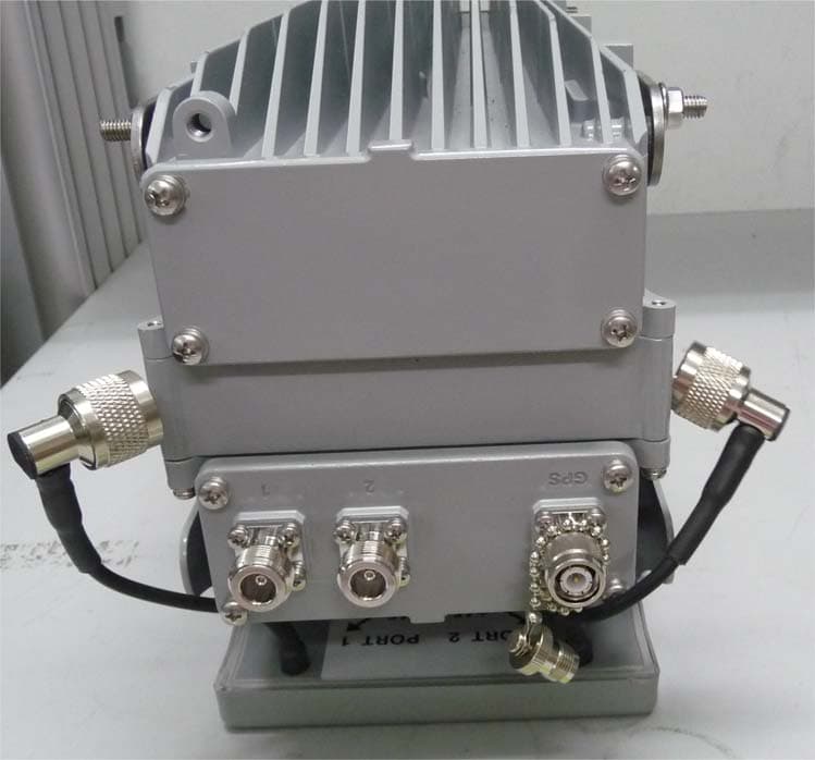
PIDAHR2500
Aug 23, 2015Base station of LTE fixed cellular system
Equipment Class
TNB - Licensed Non-Broadcast Station Transmitter