PIDAIRSPAN-IDRIndoor Data Radio (IDR)
Airspan Networks Inc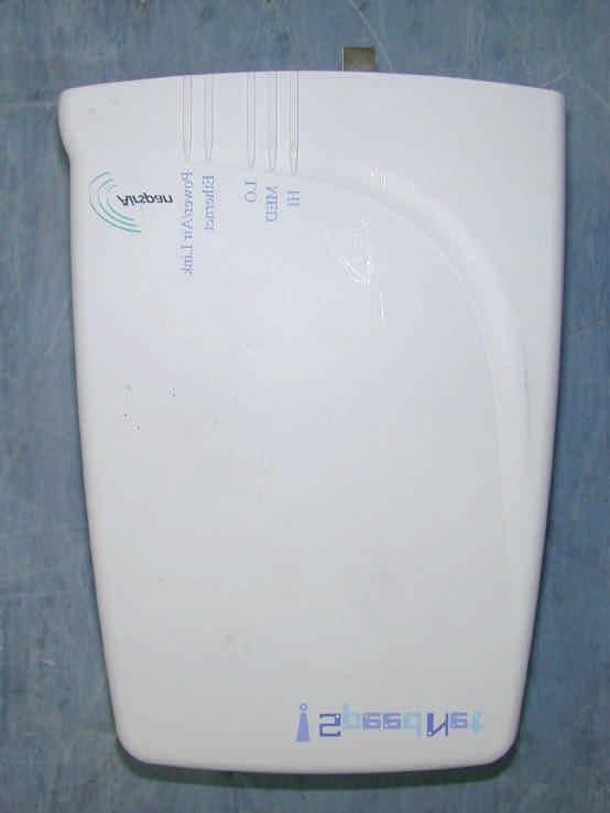
Click to zoom
Application Details
- Equipment Class
- DTS - Digital Transmission System
- Date of Grant
- Dec 30, 2003
- Application Purpose
- Original Equipment
- Date of Application
- Dec 30, 2003
- Equipment Note
- Indoor Data Radio (IDR)
- Frequency Range
- 903.00000000 - 927.00000000
- Company
- Airspan Networks Inc
- Country
- United States
Documents & Files
Document Text
Text extracted from the exhibit documents filed with the FCC. Open a document above to read the original.
Users Manual
FCC Declaration of Conformity We, the undersigned, Company: Airspan Networks Inc Address: 777 Yamato Road Suite 105 Boca Raton, FL 33431 Country: USA Telephone number: +1 561 893-8670 Fax number: +1 561 893-8671 are the Responsible Party for this Declaration, certify and declare under our sole responsibility that the following equipment: Brand Type Product description Airspan IDR Ext 900MHz Indoor Radio complies with Part 15 of the FCC Rules. Operation is subject to the following two conditions: (1) this device may not cause harmful interference, and (2) this device must accept any interference received, including interference that may cause undesired operation. on ...23 / 12/ 2003................................. (date) .................................... .................................... (signature) .................................... (name and function)
Users Manual
02030311-06 Airspan Networks Ltd. 10-1 Installing the IDR Installing the IDRInstalling the IDR Installing the IDR This chapter describes the installation of the WipLL Indoor Data Radio (IDR), which is installed at the base station. This chapter includes the following sections: ! Overview ! Physical Dimensions and Basic Design ! Mounting the IDR ! Desk Mounting ! Wall and Pole Mounting ! Connecting a Third-Party External Antenna ! Connecting to an Ethernet Network ! Positioning IDR for Optimum RF Reception ! Connecting to PC for Serial Configuration ! Connecting Power ! Power LEDs Warning: When operating in the 900 MHz band, the IDR model with an external antenna must not be co-located or operating in conjunction with any other antenna or transmitter. 10 Installing the IDR Hardware Installation Guide 10-2 Airspan Networks Ltd. 02030311-06 10.1. Overview The IDR device is an optional WipLL device that combines the functionality of the SPR and SDA devices. The IDR has a built-in antenna that provides an interface for transmission with the base station. In addition, the IDR provides an interface for 10Base-T Ethernet with the subscriber's network. However, unlike the SDA, a separate power supply unit (power adapter) powers the IDR. The IDR is available in two models: ! IDR with an internal antenna ! IDR with a TNC connector for connecting to a third-party external antenna RF link t o BSR Optional external Optional externalOptional external Optional external antenna antennaantenna antenna RF cable IDR PC RF link t o BSR Optional external Optional externalOptional external Optional external antenna antennaantenna antenna RF cable IDR PC Figure 10-1: Typical IDR setup at subscriber's premises (showing optional antenna) Hardware Installation Guide Installing the IDR 02030311-06 Airspan Networks Ltd. 10-3 Warning: To avoid electrical or fire hazard, ensure that all connections to the IDR are performed prior to connecting the power supply. Note: The digital portion of the transceiver has been tested and found to comply with the limits for a Class B digital device, pursuant to part 15 of the FCC rules. These limits are designed to provide reasonable protection against harmful interference in a residential installation. This equipment generates, uses, and can radiate radio frequency energy and, if not installed and used in accordance with the instructions, may cause harmful interference to radio communications. However, there is no guarantee that interference will not occur in a particular installation. If this equipment does cause harmful interference to radio or television reception, which can be determined by turning the equipment on and off, the user is encouraged to try correct the interference by performing one or more of the following measures: - Reorientate or relocate the receiving antenna - Increase separation between the equipment and receiver - Connect the equipment to an outlet on a circuit different from that to which the receiver is connected - Consult the dealer or an experienced radio/TV technician for help Installing the IDR Hardware Installation Guide 10-4 Airspan Networks Ltd. 02030311-06 10.2. Physical Dimensions and Basic Design The IDR is encased in a chassis providing access to the IDR's communication port at the front panel. Figure 10-2: IDR front panel with cover removed exposing ports The IDR's physical dimensions are described in Table 10-1. Table 10-1: IDR physical dimensions Parameter Value Comment Weight 1,43 kg Dimensions (H x W x D) • IDR with built-in antenna • IDR with an external antenna • 155 mm (6.1 inches) x 233 mm (9.17 inches) x 74.5 mm (2.93 inches) • 120.5 mm (4.74 inches) x 61mm (2.4 inches) x 35 mm (1.37 inches) Note: Dimensions exclude the external power adapter. TNC-type connector for 3 rd party external antenna RJ-11 serial port Molex 6-pin power port LEDs RJ-45 10Base-T port Chassis cover bolt Hardware Installation Guide Installing the IDR 02030311-06 Airspan Networks Ltd. 10-5 10.3. Mounting the IDR The IDR may be mounted in the following ways: ! Desk ! Pole ! Wall Note: Before mounting or attaching any brackets to the IDR, ensure that all cables are securely attached and that the unit functions correctly in the proposed location. 10.3.1. Desk Mounting The IDR may be mounted on a desk in one of the following ways: ! Vertically ! Horizontally Installing the IDR Hardware Installation Guide 10-6 Airspan Networks Ltd. 02030311-06 10.3.1.1. Vertical-Desk Mounting A base plate is provided to mount the unit vertically on the desk, i.e., in standing position. The base plate is designed to fit in one position only. To desk mount the IDR in a vertical position: ! Insert the IDR into the base and press firmly until the tabs click into place. See Figure 10-3. Figure 10-3: IDR vertical desk mounting Desk- mounting plate Hardware Installation Guide Installing the IDR 02030311-06 Airspan Networks Ltd. 10-7 10.3.1.2. Horizontal-Desk Mounting To position the IDR horizontally on the desk, four rubber pads, supplied with the unit, must be fitted to avoid damage to mounting surfaces. mTo desk mount the IDR in a horizontal position: ! Secure the rubber pads to the posts provided on the rear of the IDR using four self-tapping screws. See Figure 10-4. Figure 10-4: IDR horizontal desk mounting using supplied rubber pads and tapping screws Rubber foot Screw Installing the IDR Hardware Installation Guide 10-8 Airspan Networks Ltd. 02030311-06 10.3.2. Wall and Pole Mounting The IDR may be mounted to a wall or to a 5-cm diameter pole. Wall and pole mounting both use the same mounting brackets and wall hanger plate. 10.3.2.1. Assembling the Bracket and Hanger Plate The wall hanger plate secures the IDR to a wall or pole. The wall bracket and hanger plate allows positioning the IDR in the correct orientation. Holes are provided in the wall hanger plate for both pole and wall mounting options To assemble the bracket and hanger plate: 1. Insert a 4 mm hex nut into the slot on the t…
Text truncated - open the document above for the full version.
Users Manual
02030311-06 Airspan Networks Ltd. 2-1 Safety Guidelines Safety GuidelinesSafety Guidelines Safety Guidelines This chapter outlines general safety guidelines when installing the WipLL system. This chapter includes the following sections: ! General Safety Guidelines ! Electrical Safety Guidelines ! Handling Electrostatic Devices ! Grounding ! Lightening Protection ! Installing Outdoor Units and Third-Party External Antennas ! Radio Interference Prevention ! Cabling ! General ! Labeling 2 Safety Guidelines Hardware Installation Guide 2-2 Airspan Networks Ltd. 02030311-06 2.1. General Safety Guidelines The following lists general safety guidelines when working with the WipLL equipment: ! The user and the installer should be aware that changes and modifications not expressly approved by Airspan Networks could void the userís authority to operate the equipment. ! Never install equipment that is damaged. ! Only qualified personnel should be allowed to install, replace, and service the WipLL equipment. 2.2. Electrical Safety Guidelines The following lists electrical safety guidelines when working with the WipLL equipment: ! Disconnect all power when installing ! Never install the equipment during stormy weather and lightening Hardware Installation Guide Safety Guidelines 02030311-06 Airspan Networks Ltd. 2-3 2.2.1. Handling Electrostatic Devices Electrostatic devices are those devices that may be damaged by the inadvertent discharge of static electricity from a charged body. The risk of damage, due to electrostatic discharge (ESD) to a device, may cause the device to fail suddenly, or it may induce a partial defect within the device, which will cause subsequent premature failure. Static electricity can result from operators walking on floors, moving around on chairs, from the movement of operator's clothing or even casual brushing against racks, benches or walls. Airspan recommends the following guidelines to be adopted to minimize the risk of component failure due to electrostatic discharge to the device: ! WipLL devices are provided typically in see-through anti-static bags. Wherever possible, checking and inspection of a unit should occur without removing it from the bag. ! All operators shall wear the approved conductive overall. ! Where operators come into direct contact with any piece of electronic hardware, operators must wear an ESD-preventive wrist strap. All straps and cords should be tested using a Wrist Strap Tester prior to use. The wrist strap cords shall have a 2 Meg Ohm resistor fitted at either end. Wrist straps should be worn in direct contact with bare skin and not over clothing. Warning: Under no circumstances is it permissible for units to be handled by unprotected operators. Safety Guidelines Hardware Installation Guide 2-4 Airspan Networks Ltd. 02030311-06 2.2.2. Grounding Only certain WipLL devices require additional grounding. WipLL devices that do not require additional grounding have grounding at the main supply outlet. The following table lists the WipLL devicesí grounding requirements. Site WipLL device Grounding BSR Through the mains (via BSDU) BSDU Additional grounding required (grounding lug at rear end of chassis) Base Station BSPS Additional grounding required (grounding lug at rear end of chassis) SPR Through the mains (via SDA) CPE IDR Through the mains 2.3. Lightening Protection WipLL devices comply to the Surge Immunity standard: EN 61000-4-5. WipLL devices are protected from lightening surges as the outdoor devices (BSRs and SPRs) are encased in a plastic chassis. Therefore, if lightening strikes the device, an electrical circuit cannot be completed, and hence, no electrical surge can occur. In addition, WipLL outdoor and indoor (SDA) devices provide high speed data line protection against direct and induced transient over-voltages surges on the cables. This capability is provided by the fact that all WipLL device are designed with TVS (transient voltage suppressor) components that maintain potential differences. However, for geographical areas that have above normal lightening activity, Airspan can supply a surge protector composed of a 15-pin D-type adapter with a grounding wire. Hardware Installation Guide Safety Guidelines 02030311-06 Airspan Networks Ltd. 2-5 2.4. Installing Outdoor & Indoor Units and Third-Party External Antennas Warning: It is the responsibility of the person installing the WipLL system to ensure that when using the outdoor antenna kits in the United States (or where FCC rules apply), that only those antennas certified with the product are used. The use of any antenna other than those certified with the product is expressly forbidden in accordance with FCC rules CFR47 part 15.204. The installer should configure the output power level of antennas according to country regulations and per antenna type. Warning: Outdoor, Indoor units and antennas should be installed ONLY by experienced installation professionals who are familiar with local building and safety codes and, wherever applicable, are licensed by the appropriate government regulatory authorities. Failure to do so may void Airspanís WipLL product warranty and may expose the end user or the service provider to legal and financial liabilities. Airspan and its resellers or distributors are not liable fo r injury, damage or violation of regulations associated with the installation of outdoor units or antennas. Warning: When operating in the 900 MHz band, the IDR model with an external antenna must not be co-located or operating in conjunction with any other antenna or transmitter. Warnings: 1) The device cannot be sold retail, to the general public or by mail order. It must be sold to dealers. 2) Installation must be controlled. 3) Installation must be performed by licensed professionals. 4) Installation requires special training. Safety Guidelines Hardware Installation Guide 2-6 Airspan Networks Ltd. 02030311-06 2.6. Radio Interference Prevention The digital portion of the transcei…
Text truncated - open the document above for the full version.
Users Manual
02030311-06 Airspan Networks Ltd. C-1 Technical Specifications Technical SpecificationsTechnical Specifications Technical Specifications This appendix lists the technical specifications for the following WipLL units: ! WipLL Base Station equipment: ! Base Station Radio (BSR) ! Point-to-Point Radio (PPR) ! Base Station Distribution Unit (BSDU) ! Base Station Power Supply (BSPS) ! GPS antenna ! WipLL Customer premises equipment: ! Subscriber Premises Radio (SPR) ! Subscriber Data Adapter (SDA) − SDA-1 − SDA-4H − SDA-4S models ! Indoor Data Radio (IDR) C Technical Specifications Hardware Installation Guide C-2 Airspan Networks Ltd. 02030311-06 C.1. Base Station WipLL Equipment The following sub-sections list the specifications of the following WipLL Base Station equipment: ! Base Station Radio (BSR) ! Point-to-Point Radio (PPR) ! Base Station Distribution Unit (BSDU) ! Base Station Power Supply (BSPS) Hardware Installation Guide Technical Specifications 02030311-06 Airspan Networks Ltd. C-3 C.1.1. Base Station Radio (BSR) Table C-1: BSR and MAC Specifications Parameter Value Comment Operating frequency range • 2.4 GHz • 3.x GHz, MMDS, 2.8 • 5.8 GHz • 900 MHz • 700 MHz • ISM band • Licensed band • Unlicensed • Unlicensed • Licensed *Other ranges available for trial Spectrum spreading method Frequency hopping Per ETSI EN301 253 Duplex method • Time Division Duplex (TDD): 2.4 GHz, 2.8 GHz, 3.x GHz, MMDS, 900 MHz, 700 MHz, and 5.8 GHz • Frequency Division Duplex (FDD): 3.x GHz Transmit bit rates Up to 4 Mbps BER and distance dependent Channel spacing 1 MHz For 3.5 GHz the channel spacing can be 1 MHz or 1.75 MHz Output power from the BSR Up to 27 dBm (configurable) Depending on local regulations, maximum output power can be configured at the factory Modulation method 8-level CPFSK Channel access method PPMA / Adaptive TDMA Protocol efficiency Up to 80% For large data packets Number of SPR/IDR per BSR Up to 126 Technical Specifications Hardware Installation Guide C-4 Airspan Networks Ltd. 02030311-06 Table C-2: BSR EMC and Radio Standards Compliance Parameter Value Radio Standards Compliance • ETSI EN 300 328-1 • ETSI EN 301 253 • FCC part 15 • RSS139 • Telec EMC • ETSI ETS 300 826 • ETSI EN 300 385 • ETSI EN 300 386-2 • ETSI ETS 300 132-2 • FCC part 15 Table C-3: BSR Agency Certification Parameter Value Emissions / Immunity EN 300 339 EN 300 386-2 ETS 300 328 Safety EN / IEC 60950 Environmental ETS 300 019-2-x Table C-4: BSR Network Specifications Parameter Value Comment Filtering Rate 10,500 frames/sec At 64 byte packets Forwarding Rate 1,300 frames/sec At 64 byte packets Routing table length 200 networks, including subnets Table C-5: BSR Power Requirements Parameter Value Comment Voltage • Minimum: • Maximum: 48 VDC nominal • 30 VDC • 55 VDC Voltage is received from the BSDU or SDA, depending on base station setup Maximum Amperes: 500 mA Hardware Installation Guide Technical Specifications 02030311-06 Airspan Networks Ltd. C-5 Table C-6: BSR Environmental Conditions Parameter Value Comment Operating temperature of outdoor units (BSR and SPR) -30∫C to +60∫C Optional range of -40∫C to +70∫C Storage temperature -40∫C to +80∫C Table C-7: BSR Network Interface Parameter Value Comment Ethernet Network UTP EIA/TIA Category 5 Standards Compliance ANSI/IEEE 802.3 and ISO/IEC 8802-3 10Base-T compliant Serial Port RS-232 Table C-8: BSR Physical Dimensions Parameter Value Comment Height 400 mm (15.74 inches) Width 317 mm (12.48 inches) Depth 65.5 mm (2.58 inches) Weight 4.7 kg Excluding mounting kit Technical Specifications Hardware Installation Guide C-6 Airspan Networks Ltd. 02030311-06 C.1.2. Point-to-Point Radio (PPR) Table C-9: PPR Radio Specifications Parameter Value Operating frequency bands • 2,400 to 2,500 MHz • 3,400 to 3,800 MHz • 5,725 to 5,875 MHz Duplex method • Time Division Duplex (TDD) for all bands • Frequency Division Duplex (FDD) for 3.4 to 3.8 GHz Radio Technology FH-CDMA Multiple Access Method PPMA Output power 27 dBm Antenna type (built-in) • PPR • SPR • 18 dBi / 15 dBi • 18 dBi / 15 dBi Sub-Channel Spacing 1 MHz Modulation Multilevel (2, 4, or 8) CPFSK Receiver Sensitivity (BER 1E- 6 at 2/4/8 FSK) -90/ -83/ -75 dBm Throughput Up to 4 Mbps per PPR-SPR link Radio Standards Compliance • ETSI EN 300 328-1 • ETSI EN 301 253 • FCC part 15 • RSS139 • Telec EMC • ETSI ETS 300 826 • ETSI EN 300 385 • ETSI EN 300 386-2 • ETSI ETS 300 132-2 • FCC part 15 Hardware Installation Guide Technical Specifications 02030311-06 Airspan Networks Ltd. C-7 C.1.3. Base Station Distribution Unit (BSDU) Table C-10: BSDU Network Specifications Parameter Value Filtering Rate 105,000 Frames / sec Forwarding Rate 62,500 Frames / sec Table C-11: BSDU Power Requirements Parameter Value Voltage 48VDC nominal Power consumption Maximum 300W (including the feeding of 6 ◊ BSRs) Table C-12: BSDU Environmental Conditions Parameter Value Operating Temperature 0∫C to +50∫C Storage Temperature -40∫C to +80∫C Table C-13: BSDU Network Interface Parameter Value Comment Ethernet Network 100/10Base-T: UTP EIA/TIA Category 5 Standards Compliance ANSI/IEEE 802.3, ISO/IEC 8802-3 10/100 Base-T compliant Serial Port RS-232 Table C-14: BSDU Physical Dimensions Parameter Value Height 4.32 cm Width 48.26 cm Depth 22.86 cm Weight 2.9 kg Technical Specifications Hardware Installation Guide C-8 Airspan Networks Ltd. 02030311-06 C.1.4. Base Station Power Supply (BSPS) Table C-15: BSPS Rectifier Specifications Parameter Value Voltage 90VAC to 270VAC Current (nominal) 3.2A @ 230V / 4.3A @ 115V Frequency 47Hz to 63Hz Input Power factor (nominal line/load) Greater or equal to 0.993 Voltage (default) 53.5VDC Regulation (line & load) ±0.4% Adjustable range 47 to 58 VDC Current 12A @ 54V Ripple & noise 50mVp-p Efficiency (nominal load) 85% @ 230V / 82% @ 115V Overload current <12A Over-voltage protection 60 VDC Over-temperature protection (measured on case, upper panel corner) • 80±5∞C rectifier stops • 72±5∞C rectifier recovers Walk-in time < 0.…
Text truncated - open the document above for the full version.
Users Manual
02030311-06 Airspan Networks Ltd. D-1 FCC Declaration of FCC Declaration of FCC Declaration of FCC Declaration of Conformity for IDR Conformity for IDRConformity for IDR Conformity for IDR We, Airspan Networks Inc., Company: Airspan Networks Inc Address: 777 Yamato Road Suite 105 Boca Raton, FL 33431 Country: USA Telephone number: +1 561 893-8670 Fax number: +1 561 893-8671 are the Responsible Party for this Declaration, certify and declare under our sole responsibility that the following equipment: Brand Type Product description Airspan Networks Inc IDR Ext 900MHz Indoor Radio complies with Part 15 of the FCC Rules. Operation is subject to the following two conditions: (1) this device may not cause harmful interference, and (2) this device must accept any interference received, including interference that may cause undesired operation. D
Users Manual
Connecting the World with Wireless Access Solutions WipLL and AS3010 WipLL and AS3010 WipLL and AS3010 WipLL and AS3010 Systems SystemsSystems Systems Wireless IP-Based Local Loop System Release 4.2B Hardware Installation Guide The WipLL product bears the CE marking. This CE marking demonstrates WipLL's full compliance with applicable European Union (EU) directives: The WipLL product bears the Underwriters Laboratories (UL) marking, demonstrating full compliance with UL's safety requirements: WipLL products also bear the Federal Communications Commission (FCC) marking, demonstrating compliance with FCC Part 15 regulations. Revision Record: WipLL Hardware Installation Guide Pub. Rev. Date Update Description - Nov-00 First edition and printing. (Marconi) - Mar-01 WipLL Release 1.4 (Marconi) - Apr-01 WipLL Release 2.0 (Marconi) - Jul-01 WipLL Release 2.2 (Marconi) - Nov-01 WipLL Release 2.6 (Marconi) - Jun-02 WipLL Release 3.0A (Marconi) 01 Feb-03 WipLL Release 4.0. Author: InterDoc. Updates: Airspan template and content (connector pinouts; cable crimping, and general) 02 May-03 WipLL Release 4.2F. Author: InterDoc. Updates: graphics, deleted BSR with serial port. 03 Jul-03 WipLL Release 4.2A. Author: InterDoc. Updates: Chapter 1 for Transparent Bridging; 5.8 GHz; 2.8 GHz. 04 Aug-03 WipLL Release 4.2A. Author: InterDoc. Updates: formatting; graphics; BSDU LEDs 05 Oct-03 WipLL & AS3010 Rel. 42B. Auth: InterDoc. Updates: RSSI Plug for SPR; IDR RSSI levels; SDA-4S/Vltag; safety guidelines; Append. D. Publication No. 02030311-05 Copyright by Airspan Networks LTD., 2003. All rights reserved worldwide. The information contained in this document is proprietary and is subject to all relevant copyright, patent and other laws protecting intellectual property, as well as any specific agreement protecting Airspan Networks LTD. rights in the aforesaid information. Neither this document nor the information contained herein may be published, reproduced or disclosed to third parties, in whole or in part, without the express, prior, written permission of Airspan Networks LTD. In addition, any use of this document or the information contained herein for any purposes other than those for which it was disclosed is strictly forbidden. Airspan Networks LTD. reserves the right, without prior notice or liability, to make changes in equipment design or specifications. Information supplied by Airspan Networks LTD. is believed to be accurate and reliable. However, no responsibility is assumed by Airspan Networks LTD. for the use thereof nor for the rights of third parties which may be effected in any way by the use thereof. Any representation(s) in this document concerning performance of Airspan Networks LTD. product(s) are for informational purposes only and are not warranties of future performance, either express or implied. Airspan Networks LTD. standard limited warranty, stated in its sales contract or order confirmation form, is the only warranty offered by Airspan Networks LTD. in relation thereto. This document may contain flaws, omissions or typesetting errors; no warranty is granted nor liability assumed in relation thereto unless specifically undertaken in Airspan Networks LTD. sales contract or order confirmation. Information contained herein is periodically updated and changes will be incorporated into subsequent editions. If you have encountered an error, please notify Airspan Networks LTD. All specifications are subject to change without prior notice. Main Operations: Airspan Communications Ltd. Cambridge House Oxford Road Uxbridge Middlesex UB8 1UN United Kingdom Tel: (44)-895 467100 Web site: http//www.airspan.com Customer Service (TAC): [email protected] or (+972) 8 929 2266 This page is intentionally left blank. Hardware Installation Guide Contents 02030311-05 Airspan Networks Ltd. v Contents About this Manual................................................................................................ xiii Purpose ....................................................................................................... xiii Targeted Audience ...................................................................................... xiii Organization of this manual......................................................................... xiv Conventions ................................................................................................. xv Technical support ......................................................................................... xv 1. Introduction .............................................................................................. 1-1 1.1. Main Features ..................................................................................... 1-2 1.2. Customer Benefits............................................................................... 1-3 1.3. System Architecture ............................................................................ 1-4 1.3.1. Base Station ......................................................................... 1-5 1.3.2. Subscriber Site ..................................................................... 1-8 1.3.3. Network Operations Center ................................................ 1-12 1.4. Applications ....................................................................................... 1-13 1.4.1. Broadband Data Access ..................................................... 1-13 1.4.2. High Speed Internet Access ............................................... 1-14 1.4.3. Voice over IP ...................................................................... 1-15 1.4.4. Traffic Engineering in Multi-Tenant Application .................. 1-16 1.4.5. Repeater Solution ............................................................... 1-17 2. Safety Guidelines ..................................................................................... 2-1 2.1. General Safety Guidelines ..........................................…
Text truncated - open the document above for the full version.
Users Manual
Installing the BSPS Hardware Installation Guide 7-28 Airspan Networks Ltd. 02030311-05 Symptom Possible Cause Remedy between any two modules). • Rectifier(s) are not properly adjusted. • Re-adjust the voltage of the problematic rectifier(s). Battery backup time is too low • Battery is too small for the application. • Charging voltage is too low • Weak battery • Increase battery capacity • Raise the system output voltage using the ìVOLT ADJ.î • Replace the battery and check ambient temperature according to manufacturerís instructions Part II Part IIPart II Part II Installing WipLL Customer Installing WipLL Customer Installing WipLL Customer Installing WipLL Customer Premises Equipment Premises EquipmentPremises Equipment Premises Equipment Part II describes the procedures for installing the WipLL equipment located at the subscriberís premises. Part II includes the following chapters: ! Chapter 8, ìInstalling the SPRî ! Chapter 9, ìInstalling the SDAî ! Chapter 10, ìInstalling the IDRî This page is intentionally left blank. 02030311-05 Airspan Networks Ltd. 8-1 Installing the SPR Installing the SPRInstalling the SPR Installing the SPR This chapter describes the installation of the WipLL Subscriber Premises Radio (SPR) at the subscriber's premises. This chapter includes the following chapters: ! Overview ! Physical Dimensions and Basic Design ! Cable Guidelines ! Mounting the SPR ! Minimum Distance between SPRs ! Wall Mounting ! Pole Mounting ! Connecting an External Third-Party Antenna (Optional) ! Connecting to the SDA ! Connecting to a PC for Serial Configuration ! Connecting the RSS LED Adapter ! Connecting Power 8 Installing the SPR Hardware Installation Guide 8-2 Airspan Networks Ltd. 02030311-05 8.1. Overview The SPR receives and transmits data from and to the base station. The SPR connects to the subscriberís network through the SDA. The SDA is an Ethernet hub/LAN switch (depending on SDA model) that provides the SPR with DC power, lightening protection, and Ethernet (10Base-T and/or 100Base-T )connectivity to the subscriberís PCs/network (up to four PCs depending on SDA model). The SPR connects to the SDA by a CAT-5 cable. The SPR is typically mounted on the subscriber's roof or external wall; the SDA is installed inside the subscriber's premises. The SPR is available in the following models: ! SPR with Standard Gain: includes a built-in antenna 15-dBi antenna gain, covering an area of 23 degrees ! SPR with High-Gain Antenna: includes a built-in antenna with an 18-dBi antenna gain, covering 15 degrees. ! SPR with External Antenna: includes an N-type connector port for attaching a third-party external antenna. Figure 8-1 displays a typical setup of the SPR and SDA at the subscriber's premises. Note: The SDA can also be installed at a base station that has only one BSR. This SDA replaces the need for the BSDU, and provides power and connectivity to the single BSR. Hardware Installation Guide Installing the SPR 02030311-05 Airspan Networks Ltd. 8-3 RF link CAT-5e PC Figure 8-1: Typical SPR and SDA location and connections at subscriber's premises Warning: As the system emits microwave radiation, a minimum distance o f 200 mm must be maintained from the front of the SPR. To avoid electrical or fire hazard, connect the SPR to the power supply only after mounting the SPR and connecting data cables between the SPA and SDA units. Note: Usually, the SPR is initialized (i.e., configured with an IP address) at Airspan's factory. However, if the SPR has not been configured, see Section 8.7, ìConnecting to a PC for Serial Configurationî, before mounting the SPR. Subscriber Data Adapter (SDA) located inside Subscriber Premises Radio (SPR) located on the roof Installing the SPR Hardware Installation Guide 8-4 Airspan Networks Ltd. 02030311-05 Note: The digital portion of the transceiver has been tested and found to comply with the limits for a Class B digital device, pursuant to part 15 of the FCC rules. These limits are designed to provide reasonable protection against harmful interference in a residential installation. This equipment generates, uses, and can radiate radio frequency energy and, if not installed and used in accordance with the instructions, may cause harmful interference to radio communicat…
Text truncated - open the document above for the full version.
Contact Information
Applicant
Grant Pottash(Technical Services Director)
Technical Contact
Hermon LaboratoriesEdward Usoskin
[email protected]972 4 628-8001
Harakevet Industrial zone · Binyamina · Israel
Non-Technical Contact
Airspan Networks (Israel) Ltd.Zion Levi
[email protected]+972 3977 7444
Test Firm
Hermon Laboratories Ltd.Alexander Usoskin
Technical Specifications
| # | Rule Parts | Frequency Range | Power Output |
|---|---|---|---|
| 1 | 15C | 903 MHz - 927 MHz | 61.00 mW |
Other Applications from Airspan Networks Inc
PIDAS1035
Sep 20, 2023LTE Base Station
Equipment Class
TNB - Licensed Non-Broadcast Station Transmitter
PIDASPOT5410
Jan 10, 2021B42H/B43L/B48
Equipment Class
CBD - Citizens Band Category A and B Devices
PIDAS1030
Aug 23, 2020LTE Base Station Radio
Equipment Class
CBD - Citizens Band Category A and B Devices
PIDH4K25
Jan 27, 2016Base station of LTE fixed cellular system
Equipment Class
TNB - Licensed Non-Broadcast Station Transmitter
PIDAHR2500
Aug 23, 2015Base station of LTE fixed cellular system
Equipment Class
TNB - Licensed Non-Broadcast Station Transmitter