PIDAIRSPAN-IDR900Indoor Data Radio (IDR)
Airspan Networks Inc
Click to zoom
Application Details
- Equipment Class
- DTS - Digital Transmission System
- Date of Grant
- May 25, 2004
- Application Purpose
- Original Equipment
- Date of Application
- May 25, 2004
- Equipment Note
- Indoor Data Radio (IDR)
- Frequency Range
- 903.00000000 - 927.00000000
- Company
- Airspan Networks Inc
- Country
- United States
Documents & Files
Document Text
Text extracted from the exhibit documents filed with the FCC. Open a document above to read the original.
Users Manual
02030311-07 Airspan Networks Inc. 2-1 Safety Guidelines This chapter outlines safety guidelines when installing the WipLL system. Warning: The user and the installer should be aware that changes and modifications not expressly approved by Airspan Networks could void the user’s authority to operate the equipment. Warning: Never install equipment that is damaged. Warning: Only qualified personnel should be allowed to install, replace, and service the WipLL equipment. 2.1. Electrical Safety Guidelines Warning: Disconnect all power when installing. 2.1.1. Handling Electrostatic Devices Electrostatic devices are those devices that may be damaged by the inadvertent discharge of static electricity from a charged body. The risk of damage, due to electrostatic discharge (ESD) to a device, may cause the device to fail suddenly, or it may induce a partial defect within the device, which will cause subsequent premature failure. 2 Safety Guidelines Hardware Installation Guide 2-2 Airspan Networks Inc. 02030311-07 Static electricity can result from operators walking on floors, moving around on chairs, from the movement of operator's clothing or even casual brushing against racks, benches or walls. Airspan recommends the following guidelines to be adopted to minimize the risk of component failure due to electrostatic discharge to the device: WipLL devices are provided typically in see-through anti-static bags. Wherever possible, checking and inspection of a unit should occur without removing it from the bag. All operators shall wear the approved conductive overall. Where operators come into direct contact with any piece of electronic hardware, operators must wear an ESD-preventive wrist strap. All straps and cords should be tested using a Wrist Strap Tester prior to use. The wrist strap cords shall have a 2 Meg Ohm resistor fitted at either end. Wrist straps should be worn in direct contact with bare skin and not over clothing. Warning: To prevent ESD damage to WipLL devices, always wear an ESD wris t strap when handling these devices or coming into contact with internal components. 2.1.2. Grounding Only certain WipLL devices require additional grounding. WipLL devices that do not require additional grounding have grounding at the main supply outlet. The following table lists the WipLL devices’ grounding requirements. Table 2-1: WipLL grounding requirements Site WipLL device Grounding BSR Through the mains (via BSDU) BSDU Additional grounding required (grounding lug at rear end of chassis) Base Station BSPS Additional grounding required (grounding lug at rear end of chassis) SPR Through the mains (via SDA) CPE IDR Through the mains Hardware Installation Guide Safety Guidelines 02030311-07 Airspan Networks Inc. 2-3 2.1.3. Lightening Protection Warning: Never install the equipment during stormy weather and lightening. WipLL devices comply with the Surge Immunity standard: EN 61000-4-5. WipLL devices are protected from lightening surges as the outdoor devices (BSRs and SPRs) are encased in a plastic chassis. Therefore, if lightening strikes the device, an electrical circuit cannot be completed, and hence, no electrical surge can occur. In addition, WipLL outdoor and indoor (SDA) devices provide high-speed data line protection against direct and induced transient over-voltages surges on the cables. This capability is provided by the fact that all WipLL devices are designed with TVS (transient voltage suppressor) components that maintain potential differences. However, for geographical areas that have above normal lightening activity, Airspan can supply a surge protector composed of a 15-pin D-type adapter with a grounding wire. Safety Guidelines Hardware Installation Guide 2-4 Airspan Networks Inc. 02030311-07 2.2. Installing WipLL Radios and Third-Party External Antennas Warning: It is the responsibility of the person installing the WipLL system to ensure that when using the outdoor antenna kits in the United States (or where FCC rules apply), that only those antennas certified with the product are used. The use of any antenna other than those certified with the product is expressly forbidden in accordance with FCC rules CFR47 part 15.204. The installer should configure the output power level of antennas according to country regulations and per antenna type. Warning: Outdoor WipLL units and antennas should be installed ONLY by experienced installation professionals who are familiar with local building and safety codes and, wherever applicable, are licensed by the appropriate government regulatory authorities. Failure to do so may void Airspan’s WipLL product warranty and may expose the end user or the service provider to legal and financial liabilities. Airspan and its resellers or distributors are not liable fo r injury, damage or violation of regulations associated with the installation of outdoor units or antennas. Warning: When using external antennas, the external antennas must not be co-located or operating in conjunction with any other antenna or transmitter. Warnings: 1) The device cannot be sold retail, to the general public or by mail order. It must be sold to dealers. 2) Installation must be controlled. 3) Installation must be performed by licensed professionals. 4) Installation requires special training. Hardware Installation Guide Safety Guidelines 02030311-07 Airspan Networks Inc. 2-5 Warning: In accordance with FCC regulations, ensure that when operating in unlicensed bands, the external antennas provide an EIRP of less than or equal to 36 dBm to prevent interference with other radios operating in the unlicensed band. The EIRP is defined by the following formula: Max. Power Output + Antenna Gain - Cable Loss ≤ 36 dBm (EIRP) Thus, ensure that cable loss is sufficiently high to achieve EIRP of 36 dBm or less. The table below lists examples of cable loss per cable for maximum antenna gains, based on the formula above. Note that the EIRP is either equal to or less than 36 dBm. Safety Guid…
Text truncated - open the document above for the full version.
Users Manual
02030311-07 Airspan Networks Inc. 12-1 Installing the IDR This chapter describes the installation of the WipLL Indoor Data Radio (IDR), which is installed at the subscriber site. Warning: When operating in the 900 MHz band, the IDR model with an external antenna must not be co-located or operating in conjunction, with any other antenna or transmitter. Warning: To avoid electrical or fire hazard, ensure that all cable connections to the IDR are performed prior to connecting the power supply. Note: The digital portion of the transceiver has been tested and found to comply with the limits for a Class B digital device, pursuant to part 15 of the FCC rules. These limits are designed to provide reasonable protection against harmful interference in a residential installation. This equipment generates, uses, and can radiate radio frequency energy and, if not installed and used in accordance with the instructions, may cause harmful interference to radio communications. However, there is no guarantee that interference will not occur in a particular installation. If this equipment does cause harmful interference to radio or television reception, which can be determined by turning the equipment on and off, the user is encouraged to try correct the interference by performing one or more of the following measures: - Reorientate or relocate the receiving antenna - Increase separation between the equipment and receiver - Connect the equipment to an outlet on a circuit different from that to which the receiver is connected - Consult the dealer or an experienced radio/TV technician for help 12 Installing the IDR Hardware Installation Guide 12-2 Airspan Networks Inc. 02030311-07 12.1. Physical Dimensions and Basic Design The IDR is encased in a chassis providing access to the IDR's communication port at the front panel. The following figure displays the IDR’s front panel (when the front chassis cover is removed). Figure 12-1: IDR front panel (removed cover) exposing ports TNC-type connector for 3 rd party external antenna RJ-11 serial port Molex 6-pin power port LEDs RJ-45 10Base-T port Chassis cover bolt Hardware Installation Guide Installing the IDR 02030311-07 Airspan Networks Inc. 12-3 The IDR's physical dimensions are described in Table 12-1. Table 12-1: IDR physical dimensions Parameter Value Comment Weight 1,43 kg Dimensions (H x W x D) • IDR with built-in antenna • IDR with an external antenna • 155 mm (6.1 inches) x 233 mm (9.17 inches) x 74.5 mm (2.93 inches) • 120.5 mm (4.74 inches) x 61mm (2.4 inches) x 35 mm (1.37 inches) Note: Dimensions exclude the external power adapter. 12.2. Mounting the IDR The IDR is installed indoors. It is positioned so that the IDR (or a third-party external antenna) is in line-of-site with the WipLL Base Station (i.e., BSR). The IDR may be mounted in the following ways: Desktop Pole Wall Warning: The IDR must only be installed indoors. Airspan is not liable and responsible for any damages that may occur to the IDR if it is installed outdoors. Note: Before mounting or attaching any brackets to the IDR, ensure that all cables are securely attached and that the unit functions correctly in the proposed location. Installing the IDR Hardware Installation Guide 12-4 Airspan Networks Inc. 02030311-07 12.2.1. Desktop Mounting The IDR may be mounted on a desk in one of the following orientations: Vertically Horizontally 12.2.1.1. Vertical Desk Mounting A base plate is provided to mount the IDR vertically on a desk so that it is in a standing position. To desk mount the IDR in a vertical position: Insert the IDR into the base plate, pressing firmly until the tabs click into place (see Figure 12-2). Figure 12-2: IDR vertical desk mounting Desk- mounting plate Hardware Installation Guide Installing the IDR 02030311-07 Airspan Networks Inc. 12-5 12.2.1.2. Horizontal-Desk Mounting To position the IDR horizontally on a desk, four rubber pads, supplied with the unit, must be fitted to avoid damage to the mounting surface. To desk mount the IDR in a horizontal position: Secure the rubber pads to the posts provided on the rear of the IDR using four self-tapping screws. See Figure 12-3. Figure 12-3: IDR horizontal desk mounting using supplied rubber pads and tapping screws Installing the IDR Hardware Installation Guide 12-6 Airspan Networks Inc. 02030311-07 12.2.2. Wall and Pole Mounting The IDR may be mounted to a wall or to a 5-cm diameter pole. Wall and pole mounting both use the same mounting brackets and wall hanger plate. 12.2.2.1. Assembling the Bracket and Hanger Plate The wall hanger plate secures the IDR to a wall or pole. The wall bracket and hanger plate allows positioning the IDR in the correct orientation. Holes are provided in the wall hanger plate for both pole and wall mounting options To assemble the bracket and hanger plate: 1. Insert a 4 mm hex nut into the slot on the tilt arm component 2. Holding the nut in place, attach the tilt arm to the mounting bracket using a 4 mm socket head bolt. Hand-tighten the bolt only. See Figure 12-4. 3. Affix the complete mounting assembly to the rear of the IDR using the 4-off self-tapping screws supplied with the kit. Figure 12-4: Mounting bracket assembly Mounting Bracket Screw Tilt Arm Nut Hardware Installation Guide Installing the IDR 02030311-07 Airspan Networks Inc. 12-7 4. Attach the wall bracket assembly to wall hanger using an M4 socket-head bolt and nut as shown in Figure 12-5. The bolt is only to be hand tightened at this stage. Wall Hanger M-4 nut Screw Mounting bracket assembly Figure 12-5: Wall hanger fixing method Figure 12-6: Wall hanger & mounting bracket assembly Installing the IDR Hardware Installation Guide 12-8 Airspan Networks Inc. 02030311-07 5. Once assembled, the IDR mounting bracket assembly may be secured to the rear of the IDR using the 4-off self-tapping screws supplied in the unit fixing kit. See Figure 12-7. Figure 12-7: Mounting bracket assembly secured to IDR Self - tapping Screws Hard…
Text truncated - open the document above for the full version.
Users Manual
25030311-08 Airspan Networks Inc. H-1 External Antennas Specifications This appendix provides specifications for optional third-party external antennas for WipLL devices operating in the 900 MHz and 700 MHz bands. H.1. WipLL 900 MHz H.1.1. BSR (at Base Station) Airspan offers the following optional third-party external antennas for BSR devices operating in the 900 MHz band: Panel 35°/ 18.6 dBi Panel 120°/16 dBi Panel 62°/16 dBi Panel 90°/17 dBi Omni-Directional 360°/12 dBi (3° Lobe Tilt) Omni-Directional 360°/12 dBi (5° Lobe Tilt) Sector (65°/15.5 dBi) Omni-directional (11 dBi) H External Antennas Specifications System Description H-2 Airspan Networks Inc. 25030311-08 H.1.1.1. Panel 35°/ 18.6 dBi The Panel 35°/ 18.6 dBi antenna’s radiation pattern and physical design is shown in the figure below. Figure H-1: Panel 35°/ 18.6 dBi antenna radiation pattern The table below lists the Panel 35°/ 18.6 dBi antenna specifications. Table H-1: Panel 35°/ 18.6 dBi antenna specifications Electrical specifications Frequency range 870 – 960 MHz Polarization Vertical Gain (dBd/dBi) 16.5/18.6 Azimuth BW 35° Elevation BW 14.5° Beam Tilt 0° USLS (dB) >18 Front-to-Back Ratio (dB) 25 VSWR <1.33:1 System Description External Antennas Specifications 25030311-08 Airspan Networks Inc. H-3 Electrical specifications IM Suppression – Two 20 Watt Carriers -150 dBc Impedance 50 Ω Max. Input Power 500 Watts Lightening Protection DC Ground Mechanical specifications Weight 17.5 lbs (7.9 kg) Dimensions (LxWxD) 48.5 x 18.5 x 5 in. (1232 x 470 x 127 mm) Max. Wind Area 5.3 ft 2 (0.49 m 2 ) Max. Wind Load (at 100 mph) 213 lbf (947 N) Max. Wind Speed 125 mph (201 km/h) Radiator Material Aluminum Radome Material ABS, UV Resistant Mounting Hardware Material Galvanized Steel Connector Type 7/16 DIN (Back) Color Light gray Standard Mounting Hardware DB380 Pipe Mount Kit, included Downtilt Mounting Hardware DB5083, optional H.1.1.2. Panel 120°/16 dBi The Panel 120°/16 dBi antenna’s radiation pattern and physical design is shown in the figure below. External Antennas Specifications System Description H-4 Airspan Networks Inc. 25030311-08 Figure H-2: Panel 120°/16 dBi antenna radiation pattern (at mid-band) The table below lists the Panel 120°/16 dBi antenna specifications. Table H-2: Panel 120°/16 dBi antenna specifications Electrical specifications Frequency range 806 – 960 MHz Polarization Vertical Gain 16 dBi Half-power beam width • H-plane: 120° • E-plane: 7° Impedance 50Ω VSWR <1.4:1 Max. Power 500 W (limited by connector only) Lobe Tilt 1.25° Null Fill 25% Connector N, NE (elongated N connector), DIN, EDIN (elongated DIN connector) Lightning Protection Direct ground Mechanical specifications System Description External Antennas Specifications 25030311-08 Airspan Networks Inc. H-5 Electrical specifications Wind area 0.73 m 2 (7.87 ft 2 ) Weight 14 kg (31 lbs) Wind load at 50 m/s 1140 N (256 lbs) Depth 160 mm (6.3 in.) Width 295 mm (11.6 in.) Length 2450 mm (96.5 in.) H.1.1.3. Panel 62°/16 dBi The Panel 62°/16 dBi antenna’s radiation pattern and physical design is shown in the figure below. Figure H-3: Panel 62°/16 dBi antenna radiation pattern (at mid-band) External Antennas Specifications System Description H-6 Airspan Networks Inc. 25030311-08 The table below lists the Panel 62°/16 dBi antenna specifications. Table H-3: Panel 62°/16 dBi antenna specifications Electrical specifications Frequency range 806 – 960 MHz Polarization Vertical Gain 16 dBi Half-power beam width • H-plane: 62° • E-plane: 14° Impedance 50Ω VSWR <1.4:1 Max. Power 500 W (limited by connector only) Lobe Tilt 1.25° Null Fill 5% Connector N, NE (elongated N connector), DIN, EDIN (elongated DIN connector) Lightning Protection Direct ground Mechanical specifications Wind area 0.36 m 2 (3.9 ft 2 ) Weight 6.5 kg (14.3 lbs) Wind load at 50 m/s 560 N (126 lbs) Depth 160 mm (6.3 in.) Width 295 mm (11.6 in.) Length 1225 mm (48.2 in.) System Description External Antennas Specifications 25030311-08 Airspan Networks Inc. H-7 H.1.1.4. Panel 90°/17 dBi The Panel 90°/17 dBi antenna’s radiation pattern and physical design is shown in the figure below. Figure H-4: Panel 90°/17 dBi antenna radiation pattern (at mid-band) External Antennas Specifications System Description H-8 Airspan Networks Inc. 25030311-08 The table below lists the Panel 90°/17 dBi antenna specifications. Table H-4: Panel 90°/17 dBi antenna specifications Electrical specifications Frequency range 806 – 960 MHz Polarization Vertical Gain 17 dBi Half-power beam width • H-plane: 90° • E-plane: 7° Impedance 50Ω VSWR <1.4:1 Max. Power 500 W (limited by connector only) Lobe Tilt 1.25° Null Fill 25% Connector N, NE (elongated N connector), DIN, EDIN (elongated DIN connector) Lightning Protection Direct ground Mechanical specifications Wind area 0.73 m 2 (7.87 ft 2 ) Weight 14 kg (31 lbs) Wind load at 50 m/s 1140 N (256 lbs) Depth 160 mm (6.3 in.) Width 295 mm (11.6 in.) Length 2450 mm (96.5 in.) System Description External Antennas Specifications 25030311-08 Airspan Networks Inc. H-9 H.1.1.5. Omni-Directional 360°/12 dBi (3° Lobe Tilt) The Omni-Directional 360°/12 dBi (3° Lobe Tilt) antenna’s radiation pattern and physical design is shown in the figure below. Figure H-5: Omni-Directional 360°/12 dBi (3° Lobe Tilt) radiation pattern (at mid-band) External Antennas Specifications System Description H-10 Airspan Networks Inc. 25030311-08 The table below lists the Omni-Directional 360°/12 dBi (3° Lobe Tilt) antenna specifications. Table H-5: Omni-Directional 360°/12 dBi (3° Lobe Tilt) antenna specifications Electrical specifications Frequency range 870 – 960 MHz Polarization Vertical Gain 12 dBi Half-power beam width • H-plane: 360° • E-plane: 7° Impedance 50Ω VSWR <1.43:1 Max. Power 500 W (limited by connector only) Lobe Tilt 3° Null Fill 25% Connector N, NE (elongated N connector), DIN, EDIN (elongated DIN connector) Lightning Protection Direct ground Mechanical specifications Wind area 0.2 m 2 (2…
Text truncated - open the document above for the full version.
Users Manual
25030311-08 Airspan Networks Inc. 2-1 WipLL Radio Technology - Physical Layer The WipLL system provides wireless, local-loop connectivity between the provider’s IP-based backbone and the subscriber. This radio link is established between WipLL transceivers located at the Base Station and subscriber sites. This chapter discusses the following radio frequency (RF) physical layer issues related to the WipLL system: Frequency Hopping Spread Spectrum Modulation Frequency Bands Standards Compliance WipLL RF Antennas Radio Planning 2 WipLL Radio Technology - Physical Layer System Description 2-2 Airspan Networks Inc. 25030311-08 2.1. Frequency Hopping Spread Spectrum The WipLL system implements frequency-hopping code division multiple access (FH-CDMA) spread spectrum modulation for digital signal transmission over the air between the Base Station and the subscriber site. The WipLL system’s frequency hopping supports a channel bandwidth of 1 MHz or 1.33 MHz, and channel spacing of 1 MHz (or 1.75 MHz if operating in the 3.5 GHz band). Frequency hopping is a basic modulation techniques used in spread spectrum signal transmission. Spread spectrum enables a signal to be transmitted across a frequency band that is much wider than the minimum bandwidth required by the information signal. The transmitter "spreads" the energy, originally concentrated in narrowband, across a number of frequency band channels on a wider electromagnetic spectrum. In an FH-CDMA system, a transmitter "hops" between available frequencies according to a specified algorithm, which can either be random or predefined (see Figure 2-1). The transmitter operates in synchronization with a receiver, which remains tuned to the same center frequency as the transmitter. A short burst of data is transmitted on a narrowband signal. The transmitter then tunes to another frequency, and transmits again. Therefore, the receiver is capable of hopping its frequency over a given bandwidth several times a second (20 hops per second in the WipLL system), transmitting on one frequency for a certain period of time, then hopping to another frequency and transmitting again. The WipLL system supports a hopping speed of 50 msec hopping intervals. TIME TIME 1 1 2 2 3 3 4 4 5 5 6 6 7 7 8899101011111212 f1f1 f2f2 f3f3 f4f4 f5 f5 Frequency Each channel is 1 MHz wide Figure 2-1: An example of Frequency Hopping Spread Spectrum System Description WipLL Radio Technology - Physical Layer 25030311-08 Airspan Networks Inc. 2-3 The advantages of implementing FH-CDMA in the WipLL system include the following: Frequency Hopping Spread Spectrum (FHSS) is based on interference avoidance. Narrow band interference that does not meet the SNR blocks only a few hops, decreasing the throughput only partially. The required spectrum for an FHSS system is flexible in that it does not have to be contiguous. FHSS can coexist with other systems in the same spectrum band. To intercept transmission, a receiver must “know” the hopping sequence therefore, FHSS ensures security. Frequency diversity copes with the frequency selective fading and multipath. The RF channel obtained by the WipLL operator is divided into n 1-MHz sub- channels, with center frequencies located at integer multiples of 1 MHz (see Figure 2-2). These sub-channels are organized into a set of orthogonal hopping sequences. Several methodologies are available for creating these sequences, depending on available spectrum and local regulations. Sub-channel RF channel Assigned band Figure 2-2: Relationship between “sub-channel”, “RF channel”, and “assigned channel” WipLL Radio Technology - Physical Layer System Description 2-4 Airspan Networks Inc. 25030311-08 Table 2-1 shows an example of six orthogonal sequences that can be derived from seven sub-channels. Table 2-1: Example of six orthogonal FH sequences Sequence No. Sub-channels (frequencies) 1 0 1 2 3 4 5 6 2 0 2 4 6 1 3 5 3 0 3 6 2 5 1 4 4 0 4 1 5 2 6 3 5 0 5 3 1 6 4 2 6 0 6 5 4 3 2 1 Up to 32 such sequences, each with up to 99 sub-channels can be pre-configured in the WipLL ROM. An additional 32 sequences can be configured by the WipLL operator in the RAM to provide further flexibility. 2.2. Modulation The WipLL system is based on Continuous Phase Frequency Shift Keying (CPFSK) modulation. Frequency Shift Keying uses m different frequencies for m symbols. The simplest FSK is binary FSK, where 0 and 1 correspond to different frequencies: Figure 2-3: Graph displaying different frequencies for 0 and 1 bits FSK is similar to non-linear analogue FM, but with digital modulation. System Description WipLL Radio Technology - Physical Layer 25030311-08 Airspan Networks Inc. 2-5 FSK provides the following benefits: Non-coherent detection is possible - no carrier synchronization is required. Immunities to non-linearity - the envelope contains no information and, therefore, can be hard-limited; information is carried by zero crossings: Can be used with non-linear power amplifiers Better efficiency The FSK phase can be discontinuous or continuous, as displayed in Figure 2-4. Figure 2-4: FSK phase: discontinuous (left wave); continuous (right wave) Continuous wave is more natural than discontinuous and provides the following advantages: Smaller bandwidth (discontinuous wave causes high frequency components) Operates better when transmission link has non-linearities WipLL Radio Technology - Physical Layer System Description 2-6 Airspan Networks Inc. 25030311-08 2.3. Frequency Bands WipLL provides a Wireless Local Loop (WLL) solution in the following frequency bands: Licensed bands: 700 MHz (698 – 746 MHz) 2.5 GHz (MMDS) 2.8 GHz (TDD) 3.3 to 3.8 GHz TDD/FDD (50 or 100 MHz duplex separation) Unlicensed bands: ISM 900 MHz (902 MHz to 928 MHz) ISM 2.4 GHz (TDD) 5.8 GHz (TDD) For details on specific WipLL products, see Appendix B. System Description WipLL Radio Technology - Physical Layer 25030311-08 Airspan Networks Inc. 2-7 2.4. Sta…
Text truncated - open the document above for the full version.
Cover Letter(s)
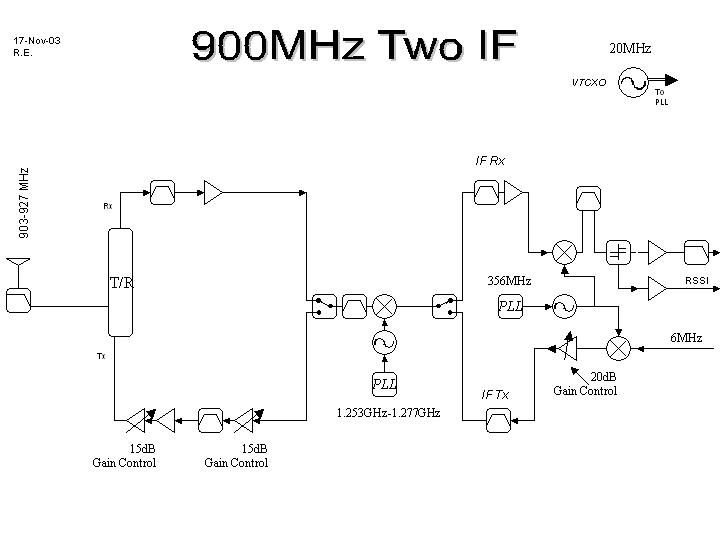
Airspan Networks (Israel) Ltd. Unitronics Bldg., 1 Harava street, P.O.B. 199, Airport City, 70100, Israel tel. +972 3977 7444 FAX: +972 3977 7400 www.airspan.com American TCB 6731 Whittier Ave Suite C110 McLean, VA 22101 USA May 3, 2004 Subject: Request for confidentiality for indoor radio adapter (hybrid system transceiver), model names IDR 900MHz TDD Ext A, IDR 900MHz TDD V-pol A, FCC ID:PIDAIRSPAN-IDR900 Dear Gentlemen, We apply to you with request to withhold Airspan Networks (Israel) Ltd. trade secrets in Application for Certification for FCC ID:PIDAIRSPAN-IDR900. These trade secrets can be found in the device schematic diagram Schematic_15693_IP (5 pages of this Application). Many thanks in advance. Sincerely yours Zion Levi compliance & testing engineer Airspan Networks (Israel) Ltd.
Cover Letter(s)
American Telecommunications Certification Body Inc. 6731 Whittier Ave, McLean, VA 22101 May 10, 2004 RE: Airspan Networks FCC ID: PIDAIRSPAN-IDR900 After a review of the submitted information, I have a few comments on the above referenced Application. 1) This FCC ID has been used for a previous application. Due to the power change, this application must be approved under a new FCC ID Number. Please correct all necessary exhibits. 2) The Block Diagram and schematics appear to show 2 external antenna connections, however from the internal photographs provided, only one connection could be located and the other was unpopulated. Please explain. From the design, it is also uncertain if both antennas can TX simultaneously. Please explain. 3) This application appears to be for both and internal and external antenna options. Please provide additional internal photographs as necessary to show the construction differences between the 2 units. 4) Please provide external photographs of the external antenna(s) to be approved with this device. 5) Please provide a list that summarized information regarding the antenna(s) to be approved with this device. For instance, type, gain, model, manufacturer, internal/external, etc. The users manual contains a lot of information. Please provide specific antennas fort his application only. To the best of our determination, It appears that there are 6.5 and 10 dBi external antennas and 8 dBi internal antennas. 6) Please provide information regarding the antenna connector to show compliance to the unique antenna requirements for the external antenna. 7) The users manual mentions external antennas for IDR are TNC (Table 2.3), but then also mentions 900 MHz IDR use N connectors (sections 2.5.2.1 & 2.5.2.3.1/2.5.2.3.2). Please clarify. 8) The users Manual table 2-14 for 900 MHz appears to show power less than reported, and possible antenna gain > than that reported. Please explain and/or correct. 9) It is not clear from plot A8 provided that the whole Ton time is shown. Please provide an updated plot. 10) Note that there is a variety of ways to approve a hybrid system (attachment for hybrids from the FCC has been provided on previous occasions). Recently approved devices for Airspan included both a FHSS and hybrid mode. Please explain if this device employs different operational modes or if it is always in hybrid mode. Note that there is a concern regarding FHSS mode only as the bandwidth is greater than that normally allowed for 900 MHz FHSS systems. The remainder of this application and comments was reviewed assuming the device is always in hybrid mode and can not normally operate in mutually exclusive modes. Other recently approved Airspan at 900 MHz only operated in hybrid mode (device does not operate in FHSS or DTS mode independently) 11) Most radiated measurements in the tables are shown as Peak measurements in the table, while all the plots referenced are average. Please explain. 12) The users manual does not appear to contain information regarding installation: “This device must not be co-located or operating in conjunction with any other antenna or transmitter". Please add or provide information as to where this information is found. Timothy R. Johnson Examining Engineer mailto: [email protected] The items indicated above must be submitted before processing can continue on the above referenced application. Failure to provide the requested information may result in application termination. Correspondence should be considered part of the permanent submission and may be viewed from the Internet after a Grant of Equipment Authorization is issued. z Page 2 May 10, 2004 Please do not respond to this correspondence using the email reply button. In order for your response to be processed expeditiously, you must submit your documents through the AmericanTCB.com website. Also, please note that partial responses increase processing time and should not be submitted. Any questions about the content of this correspondence should be directed to the sender.
Cover Letter(s)
HERM O N LA BO RA TO RIES May 11, 2004 American TCB 6731 Whittier Ave Suite C110 McLean, VA 22101 Attn: Mr. T. Johnson, Examining Engineer RE: your e-mail dated May 10, 2004; Airspan Networks Ltd. FCC ID: PIDAIRSPAN-IDR900, ATCB001313 Dear Mr. Johnson, Please find below the answers to your questions. 1) The previous application was FCC ID: PIDAIRSPAN-IDR. 2) The revised block diagram showing 1 connector was uploaded on May 11, 2004 via Block Diagram folder. 3) The IDR900 with external or internal antenna has the same PCB and the same one antenna connector. 4) Data sheets show Antennas dimensions, 10 dBi antenna is shown in Photograph No.16 of Setup photos and all photos with external antenna. 5) Three Antenna data sheets (10 dBi, 6.5 dBi, 8 dBi) were uploaded on May 11, 2004 via Additional information folder. 6) External_antenna_specification_15693_IP document was uploaded on May 11, 2004 via User Manual folder. 7) System_Description_15693_IP with corrected section 2.5.2.1 was uploaded on May 11, 2004 via Operational Description folder. 8) System_Description_15693_IP with corrected table 2-14 was uploaded on May 11, 2004 via Oper…
Text truncated - open the document above for the full version.
Contact Information
Applicant
Grant Pottash(Technical Services Director)
Technical Contact
Hermon LaboratoriesEdward Usoskin
[email protected]972 4 628-8001
Harakevet Industrial zone · Binyamina · Israel
Non-Technical Contact
Airspan Networks (Israel) Ltd.Zion Levi
[email protected]+972 3977 7444
Test Firm
Hermon Laboratories Ltd.Alexander Usoskin
Technical Specifications
| # | Rule Parts | Frequency Range | Power Output |
|---|---|---|---|
| 1 | 15C | 903 MHz - 927 MHz | 215.00 mW |
Other Applications from Airspan Networks Inc
PIDAS1035
Sep 20, 2023LTE Base Station
Equipment Class
TNB - Licensed Non-Broadcast Station Transmitter
PIDASPOT5410
Jan 10, 2021B42H/B43L/B48
Equipment Class
CBD - Citizens Band Category A and B Devices
PIDAS1030
Aug 23, 2020LTE Base Station Radio
Equipment Class
CBD - Citizens Band Category A and B Devices
PIDH4K25
Jan 27, 2016Base station of LTE fixed cellular system
Equipment Class
TNB - Licensed Non-Broadcast Station Transmitter
PIDAHR2500
Aug 23, 2015Base station of LTE fixed cellular system
Equipment Class
TNB - Licensed Non-Broadcast Station Transmitter