PIDAIRSPAN-SPRSubscriber Premises Radio
Airspan Networks Inc
Click to zoom
Application Details
- Equipment Class
- DSS - Part 15 Spread Spectrum Transmitter
- Date of Grant
- Oct 08, 2003
- Application Purpose
- Original Equipment
- Date of Application
- Oct 08, 2003
- Equipment Note
- Subscriber Premises Radio
- Frequency Range
- 5726.00000000 - 5849.00000000
- Company
- Airspan Networks Inc
- Country
- United States
Documents & Files
Document Text
Text extracted from the exhibit documents filed with the FCC. Open a document above to read the original.
Users Manual
Connecting the World with Wireless Access Solutions WipLL WipLLWipLL WipLL Wireless IP-Based Local Loop System Hardware Installation Manual For Release 4.2A Revision Record: WipLL Hardware Installation Manual for Release 4.0 Pub. Rev. Date Update Description - Nov-00 First edition and printing. (Marconi) - Mar-01 WipLL Release 1.4 (Marconi) - Apr-01 WipLL Release 2.0 (Marconi) - Jul-01 WipLL Release 2.2 (Marconi) - Nov-01 WipLL Release 2.6 (Marconi) - Jun-02 WipLL Release 3.0A (Marconi) 01 Feb-03 WipLL Release 4.0. Author: InterDoc. Updating Airspan template and content (connector pinouts; cable crimping, and general) 02 May-03 WipLL Release 4.2F. Author: InterDoc. Adding graphics, deleting BSR with serial port. 03 Jul-03 WipLL Release 4.2A. Author: InterDoc. Updating Chapter 1 for Transparent Bridging; 5.8 GHz; 2.8 GHz. Publication No. 02030311-03 Airspan Ltd. Cambridge House Oxford Road Uxbridge Middlesex UB8 1UN Tel: (44)-895 467100 Web site: http//www.airspan.com Copyright by Airspan Networks LTD., 2003. All rights reserved worldwide. The information contained in this document is proprietary and is subject to all relevant copyright, patent and other laws protecting intellectual property, as well as any specific agreement protecting Airspan Networks LTD. rights in the aforesaid information. Neither this document nor the information contained herein may be published, reproduced or disclosed to third parties, in whole or in part, without the express, prior, written permission of Airspan Networks LTD. In addition, any use of this document or the information contained herein for any purposes other than those for which it was disclosed is strictly forbidden. Airspan Networks LTD. reserves the right, without prior notice or liability, to make changes in equipment design or specifications. Information supplied by Airspan Networks LTD. is believed to be accurate and reliable. However, no responsibility is assumed by Airspan Networks LTD. for the use thereof nor for the rights of third parties which may be effected in any way by the use thereof. Any representation(s) in this document concerning performance of Airspan Networks LTD. product(s) are for informational purposes only and are not warranties of future performance, either express or implied. Airspan Networks LTD. standard limited warranty, stated in its sales contract or order confirmation form, is the only warranty offered by Airspan Networks LTD. in relation thereto. This document may contain flaws, omissions or typesetting errors; no warranty is granted nor liability assumed in relation thereto unless specifically undertaken in Airspan Networks LTD. sales contract or order confirmation. Information contained herein is periodically updated and changes will be incorporated into subsequent editions. If you have encountered an error, please notify Airspan Networks LTD. All specifications are subject to change without prior notice. Hardware Installation Manual Contents 02030311-03 Airspan Networks Ltd. i Contents About this Manual................................................................................................. vii Purpose ........................................................................................................ vii Targeted Audience ....................................................................................... vii Organization of this manual.......................................................................... vii Technical support ........................................................................................ viii 1. Introduction .............................................................................................. 1-1 1.1. Main Features ..................................................................................... 1-2 1.2. Customer Benefits............................................................................... 1-3 1.3. System Architecture ............................................................................ 1-4 1.3.1. Base Station ......................................................................... 1-5 1.3.2. Subscriber Site ..................................................................... 1-8 1.3.3. Network Operations Center ................................................ 1-11 1.4. Applications ....................................................................................... 1-12 1.4.1. Broadband Data Access ..................................................... 1-12 1.4.2. High Speed Internet Access ............................................... 1-13 1.4.3. Voice over IP ...................................................................... 1-14 1.4.4. Repeater Solution ............................................................... 1-15 2. Safety Guidelines ..................................................................................... 2-1 2.1. General Safety Guidelines .................................................................. 2-2 2.2. Electrical Safety Guidelines................................................................. 2-2 2.2.1. Handling Electrostatic Devices ............................................. 2-3 2.2.2. Grounding............................................................................. 2-4 2.3. Lightening Protection........................................................................... 2-4 Contents Hardware Installation Manual ii Airspan Networks Ltd. 02030311-03 2.4. Preventing Radio Interference............................................................. 2-5 2.5. Cabling ................................................................................................ 2-6 2.5.1. Cable Labeling...................................................................... 2-7 3. Unpacking and Required Tools .............................................................. 3-1 3.1. Unpacking and Verifying Contents ...................................................... 3-1 3.1.1. Base Station Equipment ...…
Text truncated - open the document above for the full version.
Block Diagram
17-Dec-02 R.E. IF RxIF Rx IF IF TxTx Tx VTCXOVTCXO To PLL RSSI Rx 5725 - 5850 MHz PLL PLL T/R 5.376GHz-5.499GHz 20MHz 356MHz 20dB Gain Control 20dB Gain Control (LO) 350MHz 350MHz 6MHz 6MHz (LO)
Cover Letter(s)
1 Hamelacha street, Lod, 71293, Israel tel. +972 8977 7000 FAX: +972 8977 7080 American TCB 6731 Whittier Ave Suite C110 McLean, VA 22101 USA September 22, 2003 Subject: Request for confidentiality for frequency hopping transceiver, model name SPR-5.8, FCC ID:PIDAIRSPAN-SPR Dear Gentlemen, We apply to you with request to withhold Airspan Networks (Israel) Ltd. trade secrets in Application for Certification for FCC ID: PIDAIRSPAN-SPR. These trade secrets can be found in the BSR-5.8/SPR-5.8 schematic diagrams (5 pages of this Application). Many thanks in advance. Sincerely yours Zion Levi Compliances & Testing Engineer Airspan Networks (Israel) Ltd.
Cover Letter(s)
American Telecommunications Certification Body Inc. 6731 Whittier Ave, McLean, VA 22101 September 2, 2003 RE: Airspan Networks FCC ID: PIDAIRSPAN After a review of the submitted information, I have a few comments on the above referenced Application. 1) The FRN Number provided (0009320326) appears to be invalid from checking on the FCC website. Please provide a correct FRN number for Airspan Networks Ltd. 2) It is uncertain what the difference is between the SPR and BSR models and whether they should be approved under a single FCC ID. Please provide further information regarding the differences between these 2 devices. A quick comparison seems to show that they utilize different antennas, and that the BSR contains an additional adapter for converting the sex of the input connectors. However, it also appears that the 2 devices have a different power output. If each device is manufactured with a different output value as well as each uses its own antenna configuration, these devices should be submitted under 2 different FCC ID's. This is due to the fact that the maximum measured power gets reported on the grant, and it actually appears that this will be different for each model. 3) Please note that the FCC no longer desires that the safe distance for mobile devices (devices installed such that 20 cm will be maintained between user and the antenna) be calculated in the RF exposure exhibit if the safe distance is < 20 cm, but instead prefers the power density results to be calculated and compared to the power density limit. Fixed devices (devices installed such that a 1 or 2 meter distance will be maintained between the user and the antenna) may be calculated for distance. Although the RF exposure exhibit mentions mobile, it is uncertain which category the device is being classified because of the 25 cm listed in this exhibit. Note that devices classified as mobile are listed as 20 cm. Please provide an updated RF exposure exhibit corrected as necessary. 4) If this device is classified as mobile, then the distance shown on page 31 and 131 of 229 should list 20 cm instead of 25 cm. However, given the nature of the device and the fact that additional antennas may be added (including higher gains - also see items 6 & 7 below), it may be best to classify these devices as fixed which would specify a 1, 1.5 or 2 meter distance dependent on expected conditions. Doing this will avoid any future Permissive Change application problems where TCB's are not allowed to process applications that add or change the RF exposure conditions (mobile, fixed, portable), which appear to be possible with higher gain antennas. 5) The users manual does not appear to include the information required by 15.21. Please adjust. 6) Section 4.6 of the users manual mentions the addition of an external antenna for certain model BSRs and section 8.1/8.5 mentions a similar possibility for SPR's. These model do not appear to be covered under the scope of this application and will therefore have to be addressed at a future time either as a permissive change or possibly a new certification. Additionally, please note that this application has not provided any justification for professional installation, although it appears that the external connectors (for the model BSR with external antenna connection) will not use non-standard connectors and will therefore require professional installation. Note that if professional installation is only required for certain models, these models must usually be submitted under a new FCC ID so the FCC can track these models separately. However if it is expected that these models may be added to the current application, professional installation should be addressed currently. 7) Section 8.1 of the users manual mentions SPR's with a capability of up to 18 dBi. This does not appear to be addressed by this application. Please explain. 8) Section C-11 of the users manual appears to mention the SPR with an output of 27 dBm which is higher than the 20 dBm listed in this application. Please explain. 9) FYI......The SDA or BSDU appear to normally connect to a computer and may therefore be considered a class B PC peripheral subject to the labeling and user manuals for a DoC. --- Continued on Next Page --- z Page 2September 2, 2003 10) FYI...This application does not address other models such as PPR and IDR listed in the users manual. 11) Note: Due to various concerns above, the test reports and some technical information have not yet been reviewed. Please help address the information above as soon as possible, so the remaining information can be appropriately reviewed. Timothy R. Johnson Examining Engineer mailto: [email protected] The items indicated above must be submitted before processing can continue on the above referenced application. Failure to provide the requested information may result in application termination. Correspondence should be considered part of the permanent submission and may be viewed from the Internet after a Grant of Equipment Authorization is issued. Please do not respond to this correspondence using the email reply button. In order for your response to be processed expeditiously, you must submit your documents through the AmericanTCB.com website. Also, please note that partial responses increase processing time and should not be submitted. Any questions about the content of this correspondence should be directed to the sender.
Cover Letter(s)
American Telecommunications Certification Body Inc. 6731 Whittier Ave, McLean, VA 22101 September 23, 2003 RE: Airspan Networks FCC ID: PIDAIRSPAN After a review of the submitted information, I have a few comments on the above referenced Application. 1) I believe there has been some miscommunication regarding the issue of one or two applications. Please note that the issue is not that the device may operate in either hybrid or hopping modes with 2 different powers. If the difference between powers was only due to the modes, we could accept this as a single application for both models. The concern is that there are 2 models, each utilizing different antennas and for the same mode of operation are to be approved at different power levels. The grants issued with maximum power level for the SPR would be listed at 320 mW. However, the BSR model is limited to 100 mW, it would therefore not match the grant for the equipment. Since the power level is not the same for both models for the same mode of operation this is the concern for being able to issue one grant for both models.. For instance, if the power level was the same for both models (i.e. 0.32 Watts for hopping for both models) then they could be approved under one FCC ID. Please let us know which model you wish covered by this application. so we may continue the review process. Note that all exhibits should reflect only the device being approved (external photos, internal, photos RF exposure issues, etc.) 2) Note: Due to the concerns above, the test report and some technical information has not yet been reviewed. Please help address the information above as soon as possible, so the remaining information can be appropriately reviewed. Timothy R. Johnson Examining Engineer mailto: [email protected] The items indicated above must be submitted before processing can continue on the above referenced application. Failure to provide the requested information may result in application termination. Correspondence should be considered part of the permanent submission and may be viewed from the Internet after a Grant of Equipment Authorization is issued. Please do not respond to this correspondence using the email reply button. In order for your response to be processed expeditiously, you must submit your documents through the AmericanTCB.com website. Also, please note that partial responses increase processing time and should not be submitted. Any questions about the content of this correspondence should be directed to the sender.
Cover Letter(s)
FCC ID: PIDAIRSPAN In reply to e-mail dated September 2, 2003 Dear Mr. Johnson, Below are the answers to your questions. 1. The only way I found to check the FRN was to try to change registration data (in CORES), I typed this FRN and password (I received this FRN for them) and the system showed that this FRN + password belong to Airspan Networks (Israel) ... 2. Your reply to my letter dated August 4, 2003 stated We should be able to do this under 1 ID number. The grant will likely list the 2 modes either in the grant notes, line entries or both. That is why I prepared one application for the whole system. If it appears unacceptable, may we do the following: One application (one FCC ID) for BSR in both modes (with different output powers), the other application (the second FCC ID) for SPR in both modes (with different output powers). Is it necessary to duplicate almost all the documents and to send them again with the other application or it is sufficient to submit additionally two different 731 forms and two different labels? 3. Please find an updated RF exposure exhibit, submitted via "Upload for application PIDAIRSPAN ATCB000691", RF exposure info folder on September 10, 2003. 4. Please find an updated User manual, submitted via "Upload for application PIDAIRSPAN ATCB000691", Users Manual folder on September 10, 2003. 5. The information required by 15.21 could be found on page 2-2 (28) of the initial version. It remains there in the updated version of the User Manual. 6. The BSR and SPR models covered by this application have no connectors for attaching external antennas, therefore professional installation is not required. 7. The SPR presented in the current application will not be used with high gain antenna. The antenna used with SPR in this application has 16 dBi gain. 8. There is a comment to this statement: "Depending on local regulations. Maximum power output can be set at the factory". This means that according to FCC rules the SPR under the present application will be factory programmed to produce 20/18 dBm output power. With great respect, Valeria P.S. Could you be so kind as to send your answer to my question set in Paragraph 2 as soon as possible. To: "'[email protected]'" <[email protected]> Subject: FCC ID: PIDAIRSPAN 9/23/2003file://C:\DOCUME~1\TIMOTH~1.JOH\LOCALS~1\Temp\eudCA.htm
Cover Letter(s)
Dear Mr. Johnson, as we submit two applications, the BSR and SPR will have different FCC IDs, and none of them is PIDAIRSPAN. For BSR FCC ID:PIDAIRSPAN-BSR; For SPR FCC ID: PIDAIRSPAN-SPR. Page 1 of 1In 10/9/2003Printed for "Timothy R. Johnson" <[email protected]>
External Photos
SPR general view
ID Label/Location Info
FCC ID:PIDAIRSPAN-SPR Date: August 2003 Project number:15528, 15529 Page 1 of 1 LABEL The label shown below is affixed on the bottom of the SPR-5.8 radio unit. The label material is PVC with a permanent adhesive. The FCC part 15, §15.105 statement is placed in Hardware installation Manual, page 2-5. Label placement
Internal Photos
SPR with cover removed SPR antenna SPR PCBs, first side SPR PCBs, second side RF PCB for BSR and SPR, first side RF PCB for BSR and SPR, second side
Operational Description
Raytron Ltd. Microwave, antenna and array technology 61b Bilu st., Ra’anana 43581 Telephone: 052.510.367 Fax: 09.771.5299 E- Mail Address: [email protected] Specification for: SPR Subscriber Antenna 5.8Ghz Raytron P/N: 5803-SV Airspan P/N: 901-000-26 Raytron Ltd. Microwave, antenna and array technology 1 SPR subscriber Antenna 5.8GHz Raytron P/N: 5803-SV Antenna Type: Flat Printed Antenna. Specifications: Electrical: Freq. Range (Mhz) : 5725-5875 Gain (dBi) : 16min -3dB Beam Width E-Plane (Deg) : 12 ± 1º -3dB Beam Width H-Plane (Deg) : 21 ± 2º Polarization : Linear Vertical VSWR Max : 1:1.6 Impedance (Ω) : 50 Power Handling (Watt) : 20 Sidelobes Level (dB) : -12 Front-to-back Ratio (dB) : 25 Sidelobe in the Invisible Range (120-240) (dB) : -17 Mechanical Dimensions WxH (mm) : 116x190 Input RF Interface : OSX male connector Environmental: Operating Temperature : -30 ÷ +70 Lightning Protection : Radiating elements- DC grounded Flammability UL (Std. 94) : UL 94V-0 Raytron Ltd. Microwave, antenna and array technology 2 Raytron Ltd. Microwave, antenna and array technology 3 Comparison table BSR and SPR antennas characteristics Frequency Beam Width MHz Product Matrix (XxY) (HxV) Gain dBi Pol Raytron P/N Notes BSR 1x4 60x15 11 Ver 5803BV Diversity 5725-5875 SPR 5x3 21x12 16 Ver 5803SV
Operational Description
Technical Note WipLL 5.8 GHz Wireless IP-Based Local Loop System Hopping Algorithms and Compliance with FCC 15.247 (a) (1) Connecting the World with Wireless Access Solutions Revision Record: Hopping Compliance Pub/ Rev Date Update Description 01 Jul-03 Airspan. Author: InterDoc 02 Jul-03 Airspan. Author: InterDoc. Updating of frequency tables; average time of occupancy for Hopping and Hybrid modes. 03 Oct-03 Airspan. Author: InterDoc. Adding of pseudo-random frequencies; 1.33 Mbps. Publication No. 13070311-03 Copyright by Airspan Networks LTD., 2003. All rights reserved worldwide. The information contained in this document is proprietary and is subject to all relevant copyright, patent and other laws protecting intellectual property, as well as any specific agreement protecting Airspan Networks LTD. rights in the aforesaid information. Neither this document nor the information contained herein may be published, reproduced or disclosed to third parties, in whole or in part, without the express, prior, written permission of Airspan Networks LTD. In addition, any use of this document or the information contained herein for any purposes other than those for which it was disclosed is strictly forbidden. Airspan Networks LTD. reserves the right, without prior notice or liability, to make changes in equipment design or specifications. Information supplied by Airspan Networks LTD. is believed to be accurate and reliable. However, no responsibility is assumed by Airspan Networks LTD. for the use thereof nor for the rights of third parties which may be effected in any way by the use thereof. Any representation(s) in this document concerning performance of Airspan Networks LTD. product(s) are for informational purposes only and are not warranties of future performance, either express or implied. Airspan Networks LTD. standard limited warranty, stated in its sales contract or order confirmation form, is the only warranty offered by Airspan Networks LTD. in relation thereto. This document may contain flaws, omissions or typesetting errors; no warranty is granted nor liability assumed in relation thereto unless specifically undertaken in Airspan Networks LTD. sales contract or order confirmation. Information contained herein is periodically updated and changes will be incorporated into subsequent editions. If you have encountered an error, please notify Airspan Networks LTD. All specifications are subject to change without prior notice. Frequency Hopping Compliance Contents 13070311-03 Airspan Networks Ltd. iii Contents 1. Introduction 4 2. Hopping and Hybrid System Algorithms 4 3. Hopping Time 4 4. Number of Channels 4 5. Resolution 4 6. Channel Distribution 4 7. Receiver Synchronization 4 8. Frequency Hopping and Hybrid Modes 6 8.1. Frequency Hopping Mode 6 8.2. Hybrid Mode 7 9. Receiver and Transmitter Compliance 8 9.1. Receiver Compliance with 15.247 (a) (1) / 2.1033 (a) (10) 8 9.2. Transmitter Compliance with 15.247 (g), 15.247 (h) 8 Frequency Hopping Compliance Technical Note 13070311-03 Airspan Networks Ltd. 4 1. Introduction This document provides a description of the Frequency Hopping and Hybrid systems for WipLL 5.8 GHz products. The Frequency Hopping system is for 1 Mbps, 2 Mbps and 3 Mbps; the Hybrid system (HS) is for 1.33 Mbps and 4 Mbps. 2. Hopping and Hybrid System Algorithms n The hopping algorithm is defined by a table of n frequencies, where n is greater or equal to 75 when the system is configured for 1 Mbps, 2 Mbps and 3 Mbps, and where n is greater or equal to 62 when the system is configured for 1.33 Mbps and 4 Mbps. The hopping sequence follows cyclically the frequencies in the table, remaining in each frequency for a constant period. The frequencies in the table are all in the 5.726 to 5.849 range, with at least 1 MHz between any two frequencies in the table for systems configured for 1 Mbps, 2 Mbps, and 3 Mbps; and at least 2 MHz for systems configured for 1.33 Mbps and 4 Mbps. The order of frequencies in the table is pseudorandom. n In Section 7, “Receiver Synchronization”, two modes (1 MHz-channel spacing and 2 MHz-channel spacing) are described in Table 1. 3. Hopping Time The hopping time in a given is constant (typically WipLL uses 50 msec). 4. Number of Channels The number of channels is determined by the table size n frequencies, depending on transmission speed configured for the WipLL system: n For 1 Mbps, 2 Mbps, and 3 Mbps, n is equal to at least 75 (WipLL uses n = 79) n For 1.33 Mbps and 4 Mbps, n is equal to at least 62 5. Resolution The minimum difference between any two channels is: n 1 MHz for 1 Mbps, 2 Mbps, and 3 Mbps n 2 MHz for 1.33 Mbps and 4 Mbps 6. Channel Distribution Since any used channel is included once in the table, all the channels are equally used, each channel occupying 1/n of the time. 7. Receiver Synchronization The system receiver input bandwidth filter matches the hopping channel bandwidth and synchronizes with the corresponding transmitter on the hopping sequence. Frequency Hopping Compliance Technical Note 13070311-03 Airspan Networks Ltd. 5 Table 1: Frequency Hopping System (1, 2 and 3 Mbps) and Hybrid System (4 Mbps) 15.247 Spec. Requirement WipLL Capability Comply Spread Spectrum FHSS or DSSS FHSS Yes • Minimum channel separation at 1, 2, and 3 Mbps • -20 dB bandwidth (1 MHz) • -20 dB bandwidth (1 MHz • Yes • Minimum channel separation at 4 Mbps • -20 dB bandwidth • 2 MHz • Yes List of Freq. Pseudo-random ordered list Pseudo-random ordered list Yes Use of Freq. Equal use of frequencies: 5.726 to 5.849 Constant hop period (50 msec) each frequency used once in a table Yes • Number of Frequencies at 1, 2, and 3 Mbps • Min. 75 • 79 • Yes • Number of frequencies at 1.33 Mbps and 4 Mbps • 15 non-overlapping channels with total span 123 MHz • 62 • Yes • Occupied BW per hop at 1, 2, and 3 Mbps • < 1 MHz at –20 dB • < 1 MHz at –20 dB • Yes • Occupied BW per hop at 1.33 Mbps and 4 Mbps • > 1 MHz • 1 MHz < BW < 2 MHz at –20 dB • Yes Average …
Text truncated - open the document above for the full version.
RF Exposure Info
Environmental evaluation and exposure limit according to FCC CFR 47part 1, §1.1307, §1.1310 The SPR-5.8 transceiver is classified as mobile. Limit for power density for general population/uncontrolled exposure is 1 mW/cm 2 . P T The power density P (mW/cm 2 ) = ------------- , where 4π r 2 P T is the maximum equivalent isotropically radiated power (EIRP). PT is equal to transmitter maximum output power 20 dBm plus maximum antenna gain 16 dBi, the maximum equivalent isotropically radiated power (e.i.r.p.) is 36 dBm = 4000 mW, and the power density at 20 cm (minimum safe distance, required for mobile devices), calculated as follows: 4000 / 4π 20 2 = 0.79 mW/cm 2 < 1 mW/cm 2 was found below the limit. Hence, no safety hazard exists for human being.
Test Report
This report is in conformity with ISO/IEC 17025. The A2LA logo endorsement applies only to the test methods and the standards that are listed in the scope of Hermon Laboratories accreditation. The test results relate only to the items tested. This test report must not be reproduced in any form except in full with the approval of Hermon Laboratories Ltd. Page 1 of 159 Document ID: AIRRAD_FCC.15528_1.doc Date of Issue: July 2003 HERMON LABORATORIES Electrical Hermon Laboratories Ltd. P.O.Box 23 Binyamina 30500, Israel Tel.+972 46288001 Fax.+972 46288277 e-mail: [email protected] RADIO TEST REPORT according to 47CFR Part 15, §15.247 and subpart B for Airspan Networks (Israel) Ltd. EQUIPMENT UNDER TEST: Subscriber premises radio unit Model: SPR 5.8 GHz TDD Page 2 of 159 Document ID: AIRRAD_FCC.15528_1.doc Date of Issue: July 2003 HERMON LABORATORIES Hermon Laboratories Ltd. P.O.Box 23 Binyamina 30500, Israel Tel.+972 46288001 Fax.+972 46288277 e-mail: [email protected] Contents 1 Project information........................................................................................................................................3 2 Summary of tests..........................................................................................................................................4 3 EUT description ............................................................................................................................................6 3.1 G ENERAL DESCRIPTION ................................................................................................................................................ 6 3.2 EUT TEST CONFIGURATION .......................................................................................................................................... 6 3.3 T RANSMITTER DESCRIPTION .......................................................................................................................................... 8 4 Test results .................................................................................................................................................10 4.1 O CCUPIED BANDWIDTH OF HOPPING CHANNELS AND CHANNEL CARRIER FREQUENCIES SEPARATION ACCORDING TO ß 15.247( A )(1) ........................................................................................................................................................... 10 4.2 N UMBER OF HOPPING CHANNELS ACCORDING TO ß 15.247( A )(1) ................................................................................... 11 4.3 A VERAGE TIME OF HOPPING FREQUENCY OCCUPANCY ACCORDING TO ß 15.247( A )(1), ( F )................................................ 12 4.4 M AXIMUM PEAK OUTPUT POWER TEST ACCORDING TO ß15.247 ( B )(1), ( B )(2), ( B )(3) ....................................................... 13 4.5 O UT OF BAND CONDUCTED EMISSIONS TEST ACCORDING TO ß15.247( C ) ......................................................................... 14 4.6 R ADIATED EMISSIONS WHICH FALL IN RESTRICTED BANDS TEST ACCORDING TO ß15.247( C ) AND ß 15.205, ß15.209( A )...... 15 4.7 P EAK POWER SPECTRAL DENSITY OF A HYBRID SYSTEMS ACCORDING TO ß 15.247( D ) ...................................................... 17 4.8 C ONDUCTED EMISSIONS TEST ACCORDING TO ß15.107, 15.207 .................................................................................... 18 4.9 U NINTENTIONAL RADIATED EMISSIONS TEST ACCORDING TO ß15.109.............................................................................. 19 Appendix A Plots................................................................................................................................................20 Appendix B Test setup photographs................................................................................................................139 Appendix C Example of hopping frequency.....................................................................................................144 Appendix D Test equipment …
Text truncated - open the document above for the full version.
Contact Information
Applicant
Grant Pottash(Technical Services Director)
Technical Contact
Hermon LaboratoriesEdward Usoskin
[email protected]972 4 628-8001
Harakevet Industrial zone · Binyamina · Israel
Non-Technical Contact
Airspan Networks (Israel) Ltd.Zion Levi
[email protected]972 8 977 7046
Test Firm
Hermon Laboratories Ltd.Alexander Usoskin
Technical Specifications
| # | Rule Parts | Frequency Range | Power Output |
|---|---|---|---|
| 1 | 15C | 5.73 GHz - 5.85 GHz | 100.00 mW |
Other Applications from Airspan Networks Inc
PIDAS1035
Sep 20, 2023LTE Base Station
Equipment Class
TNB - Licensed Non-Broadcast Station Transmitter
PIDASPOT5410
Jan 10, 2021B42H/B43L/B48
Equipment Class
CBD - Citizens Band Category A and B Devices
PIDAS1030
Aug 23, 2020LTE Base Station Radio
Equipment Class
CBD - Citizens Band Category A and B Devices
PIDH4K25
Jan 27, 2016Base station of LTE fixed cellular system
Equipment Class
TNB - Licensed Non-Broadcast Station Transmitter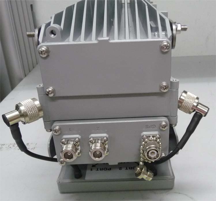
PIDAHR2500
Aug 23, 2015Base station of LTE fixed cellular system
Equipment Class
TNB - Licensed Non-Broadcast Station Transmitter