PIDAIRSPAN-SPR19Subscriber Premise Radio
Airspan Networks Inc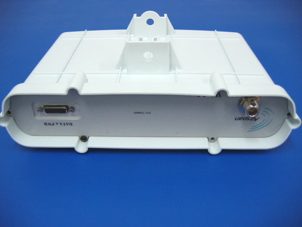
Click to zoom
Application Details
- Equipment Class
- PCB - PCS Licensed Transmitter
- Date of Grant
- Oct 26, 2005
- Application Purpose
- Original Equipment
- Date of Application
- Oct 26, 2005
- Equipment Note
- Subscriber Premise Radio
- Frequency Range
- 1852.00000000 - 1908.00000000
- Company
- Airspan Networks Inc
- Country
- United States
Documents & Files
Document Text
Text extracted from the exhibit documents filed with the FCC. Open a document above to read the original.
Attestation Statements
HERM O N LA BO RA TO RIES P.O.Box 23 Binyamina 30500 Israel Tel. +972-4628 8001 Fax +972-4628 8277 Email: [email protected] www.hermonlabs.com October 27, 2005 American TCB 6731 Whittier Ave Suite C110 McLean, VA 22101 Attn: Mr. Timothy Johnson, Examining Engineer RE: FCC ID: PIDAIRSPAN-SPR19, ATCB002771 Subject: SPR 1.9GHz FDD subscriber premises radio testing according to FCC part 24 requirements Dear Mr. Johnson, We confirm that the “SPR 1.9GHz FDD” testing was performed at the low, mid, and high channels with the hopping operation stopped on the channels. Sincerely, Michael Nikishin, EMC and Radio group leader Hermon Laboratories
Attestation Statements
American TCB 6731 Whittier Ave Suite C110 McLean, VA 22101 USA Here is the optional providers list: West Central Wireless Panhandle Telephone Poplar PCS Chariton Valley United Telephone Nemont MidRivers Golden West Golden Belt Name of authorized person: Vladimir Kvartenko Position: Hardware & Testing Engineer Date: October 11, 2005 Airspan Networks (Israel) Ltd., Harava St,”Unitronics” building, Airport City 70100, P.O.199, Israel Tel: +972-3-9777444 ; Fax: +972-3-9777400, www.airspan.com
Block Diagram
17-Nov-03R.E. IF Rx IF Rx IF IF Tx Tx Tx VTCXO VTCXO To PLL RSSI Rx 1.93-1.99 GHz PLL PLL T/R 2.2GHz-2.26GHz 20MHz 356MHz 15dB Gain Control 20dB Gain Control 15dB Gain Control 6MHz PLL 6MHz 1.85-1.91 GHz 2.28GHz-2.34GHz 350MHz 350MHz
Cover Letter(s)
Airspan Networks (Israel) Ltd. Unitronics Bldg., 1 Harava street, P.O.B. 199, Airport City, 70100, Israel tel. +972 3977 7444 FAX: +972 3977 7400 www.airspan.com September 5, 2005 American TCB 6731 Whittier Ave Suite C110 McLean, VA 22101 USA Subject: Request for confidentiality, FCC ID:PIDAIRSPAN-SPR19 Dear Gentlemen, In regards the exhibits submitted in support of the application for FCC ID:PIDAIRSPAN-SPR19, please classify the following as confidential under the provision of 47 CFR 0.459: 1) Schematic diagram, file “Schematic_16484_SPR” (5 pages) of this Application; 2) Parts list, file “Parts_list_16484_SPR” (22 pages). These exhibits contain technical information which Airspan Networks (Israel) Ltd. deems to be sensitive and proprietary. Therefore this information cannot be published. If this information were to be made public it could be used to the disadvantage of the applicant in the marketplace. Many thanks in advance. Sincerely yours Vladimir Kvartenko Hardware & Testing Engineer Airspan Networks (Israel) Ltd.
Cover Letter(s)
American Telecommunications Certification Body Inc. 6731 Whittier Ave, McLean, VA 22101 September 20, 2005 RE: Airspan Networks (Israel) Ltd. FCC ID: PIDAIRSPAN-SPR19 After a review of the submitted information, I have a few comments on the above referenced Application. 1) Test data for power measurements appears to suggest operation on 1850 and 1910 MHz channels. This is not within the band blocks and meet expectations. Please review (Power data). 2) It appears that the 731 should list 1851 – 1909 MHz with 1M82F1D, and 1852 – 1908 MHz with 2M20F1D. Please review, explain, correct as necessary. 3) Since this is based upon FSK modulation, please provide calculations to support emissions designator for both data rates. 4) This device appears to allow a hopping transmission across the band of operation. However most devices are used based upon blocks of operation, and a licensee is not necessarily allowed operation in all blocks. Please explain how this device will meet the rules given the current licensing issues based upon Part 24E blocks. 5) Section 7.4.3 appears to correct by dBi vs dBd. Shouldn’t the table therefore be EIRP? Generally the results should be ERP given the information specified in 2.1053 unless the section of the rules stipulates otherwise. 6) The results in section 7.5.2 and 7.5.3 appears incorrect. It appears that the positive and negative reported drifts are backward in the 2 tables. Which is correct? Some of the data doesn’t match at all (7.5.3, 12.316 kHz). Also for the lower frequency, it appears the results for the high side is compared against the bandedge when the low side should be used and the negative drift taken into account. Additionally the results are labeled as kHz, but appear to be MHz. Please completely review these tables for validity and correct all errors. 7) RF Exposure information appears much lower than expected if estimating based upon EIRP. Please explain? 8) Tune up procedure appears to not provide any tune up information. Please review. Information regarding tune up procedures should be provided. 9) It does not appear that a description of all circuitry and devices provided for determining and stabilizing frequency, for suppression of spurious radiation, for limiting modulation, and for limiting 10) FYI.....The labeling information regarding Part 15 appears to be more relevant to use 15.19(a)(1) instead of 15.19(a)(3). Please review.. 11) FYI....This type of system in the PCS band appears unique. In these instances, the FCC typically has asked for a list of expected providers of the equipment in the U.S. If possible, please provide. Timothy R. Johnson Examining Engineer mailto: [email protected] The items indicated above must be submitted before processing can continue on the above referenced application. Failure to provide the requested information may result in application termination. Correspondence should be considered part of the permanent submission and may be viewed from the Internet after a Grant of Equipment Authorization is issued. z Page 2 October 10, 2005 Please do not respond to this correspondence using the email reply button. In order for your response to be processed expeditiously, you must submit your documents through the AmericanTCB.com website. Also, please note that partial responses increase processing time and should not be submitted. Any questions about the content of this correspondence should be directed to the sender.
Cover Letter(s)
HERM O N LA BO RA TO RIES October 6, 2005 American TCB 6731 Whittier Ave Suite C110 McLean, VA 22101 Attn: Mr. Timothy Johnson, Examining Engineer RE: your e-mail dated September 20, 2005; Airspan Net works Ltd. FCC ID: PIDAIRSPAN-SPR19, ATCB002771 Dear Mr. Johnson, Please find below the answers to your questions. 1) The output power was measured at the highest, mid and the lowest frequencies of operation to prove compliance with standard over entire frequency band. The actual transmit frequencies will be defined by a licensee holder and a licensee bureau. 2) The revised file ATCB_Form 731_16484_SPR_rev1 was uploaded on October 6, 2005 via Application Forms folder. 3) As it is described in the ASWipll System Description document (chapters 2.2 and 2.6) the modulation is Continuous Phase FSK and the occupied bandwidth is constant for certain symbol rate (1 MSPS or 1.33 MSPS). Theoretically, the occupied bandwidth at 20 dB is 1MHz of 1MSPS mode and 1.33 MHz for 1.33 MSPS mode. The file “System_Description_16484” was uploaded on October 6, 2005 via Operational Description folder. 4) Please refer to section 8 of the corrected file Hopping_algorythm_16484_rev1, uploaded on October 6, 2005 via Operational Description folder . 5) The corrected test report AIRRAD_FCC.16484_SPR_rev1 was uploaded on October 6, 2005 via Test Report folder. 6) As above 7) The RF exposure is measured in the near field region in which the transmit antenna characteristics and EM-field propagation are non-predictable. The calculation assumes the RF exposure under far field conditions. 8) The file “Tune_up_procedure_16484_rev1” was uploaded on October 6, 2005. 9) The file “System_Description_16484” was uploaded on October 6, 2005 via Operational Description folder. 10) The file “Label_location_16484_SPR_rev1” was uploaded on October 6, 2005. 11) The Airspan’s responsible person will try to get a such list and it will be sent to you or FCC. Sincerely, Marina Cherniavsky, certification engineer Hermon Laboratories
Cover Letter(s)
American Telecommunications Certification Body Inc. 6731 Whittier Ave, McLean, VA 22101 October 10, 2005 RE: Airspan Networks (Israel) Ltd. FCC ID: PIDAIRSPAN-SPR19 After a review of the submitted information, I have a few comments on the above referenced Application. 1) The wealth of information provided in reference to previous comment 9 (as given below) does not appear to contain the information requested. Kindly point to where this information may be found in the document provided, or provide a new exhibit as necessary. It does not appear that a description of all circuitry and devices provided for determining and stabilizing frequency, for suppression of spurious radiation, for limiting modulation, and for limiting power was provided. 2) Is the information regarding previous comment 11 currently available? FYI....This type of system in the PCS band appears unique. In these instances, the FCC typically has asked for a list of expected providers. If possible, please provide. Timothy R. Johnson Examining Engineer mailto: [email protected] The items indicated above must be submitted before processing can continue on the above referenced application. Failure to provide the requested information may result in application termination. Correspondence should be considered part of the permanent submission and may be viewed from the Internet after a Grant of Equipment Authorization is issued. Please do not respond to this correspondence using the email reply button. In order for your response to be processed expeditiously, you must submit your documents through the AmericanTCB.com website. Also, please note that partial responses increase processing time and should not be submitted. Any questions about the content of this correspondence should be directed to the sender.
Cover Letter(s)
HERM O N LA BO RA TO RIES October 16, 2005 American TCB 6731 Whittier Ave Suite C110 McLean, VA 22101 Attn: Mr. Timothy Johnson, Examining Engineer RE: your e-mail dated October 10, 2005; Airspan Networks Ltd. FCC ID: PIDAIRSPAN-SPR19, ATCB002771 Dear Mr. Johnson, Please find below the answers to your questions. 1) The circuitry description, file “Hardware_description_BSR_SPR_16484” was uploaded on October 16, 2005 via Operational Description folder. 2) The providers list, file “List_providers_16484” was uploaded on October 16, 2005 via Additional Information folder. Sincerely, Marina Cherniavsky, certification engineer Hermon Laboratories
External Photos
FCC ID:PIDAIRSPAN-SPR19 Date: September 2005 Page 1 of 4 EXTERNAL PHOTOGRAPHS This document contains 3 photographs FCC ID:PIDAIRSPAN-SPR19 Date: September 2005 Page 2 of 4 Photograph No.1 SPR 1.9GHz FDD general view FCC ID:PIDAIRSPAN-SPR19 Date: September 2005 Page 3 of 4 Photograph No.2 SPR 1.9GHz FDD other side view FCC ID:PIDAIRSPAN-SPR19 Date: September 2005 Page 4 of 4 Photograph No.3 SPR 1.9GHz FDD with external antenna bottom view
ID Label/Location Info
FCC ID:PIDAIRSPAN-SPR19 Date: September 2005 Page 1 of 1 LABEL The label shown below is affixed on the bottom of the SPR 1.9GHz FDD radio unit. The label material is PVC with a permanent adhesive. SPR 1.9GHz FDD bottom, label with FCC ID:PIDAIRSPAN-SPR19 location
Internal Photos
FCC ID:PIDAIRSPAN-SPR19 Date: September 2005 Page 1 of 7 INTERNAL PHOTOGRAPHS This document contains 6 photographs FCC ID:PIDAIRSPAN-SPR19 Date: September 2005 Page 2 of 7 Photograph No.1 SPR 1.9GHz FDD internal view FCC ID:PIDAIRSPAN-SPR19 Date: September 2005 Page 3 of 7 Photograph No.2 SPR 1.9GHz FDD internal view, other side FCC ID:PIDAIRSPAN-SPR19 Date: September 2005 Page 4 of 7 Photograph No.3 SPR 1.9GHz FDD internal view without covers FCC ID:PIDAIRSPAN-SPR19 Date: September 2005 Page 5 of 7 Photograph No.4 SPR 1.9GHz FDD, RF module front view FCC ID:PIDAIRSPAN-SPR19 Date: September 2005 Page 6 of 7 Photograph No.5 SPR 1.9GHz FDD, RF module second side view FCC ID:PIDAIRSPAN-SPR19 Date: September 2005 Page 7 of 7 Photograph No.6 SPR 1.9GHz FDD, digital PCB second side view
Operational Description
1.9 GHz MA-WA19-4X 1.9 GHz Subscriber Antenna MA-WA19-4X MNT Mars 1.9 GHz Antenna provides a cost effective solution for high volume deployments, in PCS, FWA and DECT applications. Additional Features: • Aesthetic, small and unobtrusive profile blends easily with any environment. • DC grounded for lightning protection to Specifications: Electrical Frequency range 1850-1990 MHz GAIN, min. 15 dBi VSWR, max. 1:1.5 3dB Beam Width - Azimuth, Typical 20 o 3dB Beam Width - Elevation, Typical 20 o Polarization Vertical Nominal Input Impedance 50 Ohms Front to Back Ratio, Typical 20 dB Power Handling 50 W Mechanical and Environmental Dimensions (HxWxD) 305x305x15 mm RF Connector N-Type Radome PC, UV protected Lightning Protection DC Grounded Mount MNT-2 Temperature (Operating) -45°C to +60°C Specifications subject to change without notice
Operational Description
6 Hamachtesh St. Holon 58810 ISRAEL P.O.Box 5 Azur 58008 Tel:+972-3-5599661 Fax: +972-3-5599677 e-mail: [email protected] 1 1.85 - 2.025 GHz Antenna MA-WA19-AS12 Specifications: Electrical Frequency range 1.85 - 2.05 GHz GAIN, min. 12 dBi VSWR, max. 1.7: 1 3dB Beam Width - Azimuth, Typical 40° 3dB Beam Width - Elevation, Typical 40° Polarization Vertical Side-lobes Level, min. -14 dB Cross Polarization, min -15 dB Front to back, min -15 dB Power Handling 5 Watt Input Impedance 50 Ohm Mechanical and Environmental Dimensions (L x W x H) 270 x 180 x 0.8 mm Connector MCX, Male Flammability UL 94V-0 Operating Temperature -40° to +85° Lightning Protection DC Grounded Specifications subject to change without notice
Operational Description
Technical Note WipLL 1.9 GHz Wireless IP-Based Local Loop System Connecting the World with Wireless Access Solutions Revision Record: WipLL 1.9 Pub/ Rev Date Update Description 01 Aug-05 Airspan. Author: InterDoc Publication No. 28080511-01 Copyright by Airspan Networks LTD., 2003. All rights reserved worldwide. The information contained in this document is proprietary and is subject to all relevant copyright, patent and other laws protecting intellectual property, as well as any specific agreement protecting Airspan Networks LTD. rights in the aforesaid information. Neither this document nor the information contained herein may be published, reproduced or disclosed to third parties, in whole or in part, without the express, prior, written permission of Airspan Networks LTD. In addition, any use of this document or the information contained herein for any purposes other than those for which it was disclosed is strictly forbidden. Airspan Networks LTD. reserves the right, without prior notice or liability, to make changes in equipment design or specifications. Information supplied by Airspan Networks LTD. is believed to be accurate and reliable. However, no responsibility is assumed by Airspan Networks LTD. for the use thereof nor for the rights of third parties which may be effected in any way by the use thereof. Any representation(s) in this document concerning performance of Airspan Networks LTD. product(s) are for informational purposes only and are not warranties of future performance, either express or implied. Airspan Networks LTD. standard limited warranty, stated in its sales contract or order confirmation form, is the only warranty offered by Airspan Networks LTD. in relation thereto. This document may contain flaws, omissions or typesetting errors; no warranty is granted nor liability assumed in relation thereto unless specifically undertaken in Airspan Networks LTD. sales contract or order confirmation. Information contained herein is periodically updated and changes will be incorporated into subsequent editions. If you have encountered an error, please notify Airspan Networks LTD. All specifications are subject to change without prior notice. WipLL 1.9 Contents 28080511-01 Airspan Networks Ltd. iii Contents 1. Scope ................................................................................................................................4 2. SPR ...................................................................................................................................4 2.1. EUT (SPR) test configuration ................................Error! Bookmark not defined. 3. BSR ...................................................................................................................................5 3.1. EUT (SPR) test configuration ................................Error! Bookmark not defined. WipLL 1.9 Technical Note 28080511-01 Airspan Networks Ltd. 4 1. Scope This document provides a description of the WipLL 1.9 GHz product. 2. SPR A subscriber premises radio, SPR 1.9 GHz FDD Ext., is part of a WipLL broadband fixed cellular wireless access system. The system provides a radio link between an end-user (a subscriber) and a network to give high-speed data access. The SPR’s transceiver/receiver (FSK digital modulation, data rate up to 4 Mbps) uses TDM and operating in FDD duplexing mode (1,850 to 1,910 MHz Tx and 1,930 to 1,990 MHz Rx range), equipped with a 15 dBi gain external or 12 dBi internal antenna. The maximum RF output power (not including antenna gain) is 30 dBm and it can be reduced by software. The SPR is installed outdoors and typically is mounted on a pole. The SPR transmits and receives traffic to and from the base station (i.e. BSR) respectively. The transceiver provides subscribers with "always-on" Internet, high speed data only, or data and voice (VoIP) services and is configured with a unique BSR reference number, preventing the SPR from relocating to another subscriber premises without authorization. The SPR has the same PCB components as the BSR, and differs only in the software and chassis dimensions. The SPR is powered via a subscriber data adapter (SDA), which provides 48 VDC power. WipLL 1.9 Technical Note 28080511-01 Airspan Networks Ltd. 5 3. BSR A base station radio, BSR 1.9 GHz FDD Ext., is part of a WipLL broadband fixed cellular wireless access system. The system provides a radio link between an end-user (a subscriber) and a network to give high-speed data access. The BSR is a transceiver/receiver (FSK digital modulation, data rate up to 4 Mbps), using TDM and operating in FDD duplexing mode (1,850 to 1,910 MHz Rx and 1,930 to 1,990 MHz Tx range), equipped with a 16 dBi gain external or 11dBi internal antenna. The maximum RF output power (not including antenna gain) is 31dBm and it can be reduced by software. The BSR is installed outdoors and typically is mounted on a pole. The BSR transmits and receives traffic to and from the end-user (i.e. SPR) respectively. The BSR provides subscribers with "always-on" Internet, high speed data only, or data and voice (VoIP) services. The BSR is powered via a subscriber data adapter (SDA), which provides 48 VDC power.
Operational Description
1. Transmitter path Modulated digital signal from the Modem is converted to 6MHz IF signal in TxDAC AD9760 and after LC filtering reaches IF transceiver Max2511. In an internal image-reject mixer the 6MHz IF signal is mixed with 356MHz signal controlled by PLL LMX2330, the resulting 350MHz IF signal passes a gain controlled amplifier and TX SAW filter and reaches Up/Down Converter Max 2410. After combining with LO1 controlled by PLL LMX2330 the Tx RF signal passes BP filter, gain controlled amplifier, BP filter, pre-amplifier and finally a gain controlled PA. After passing through Transmit / Receive switch and LP filter the RF signal is radiated to the air by an internal or an external antenna. 2. Receiver path Received from the antenna RF signal passes LP filter, Transmit / Receive switches, BP filter and is amplified by a LNA inside the UP/Down converter MAX2410. After passing BP filter it is mixed with LO2 signal controlled by PLL LMX2330. The resulting 350MHz IF signal passes an amplifier and SAW filter and reachs IF Transciever MAX 2511. After combining with 356MHz signal 6MHz IF signal passes to the AD converter and afterwards to the Modem. 3. Determining and stabilizing frequency. All radio and IF frequencies are generated and controlled by two PLL’s LMX2330. The reference 20MHz frequence for the PLL’s is generated by an oscilator based on crystal Y1. The frequency stability of the crystal is 5 ppm and it’s temperature stability is 5 ppm. During the production the oscillator is calibrated to 20MHz with 1ppm accurancy. 4. Suppression of spurious radiation. Spurious radiation is suppressed by BP, LP and SAW filters. Bandwidth of all BP filters is 75MHz and the attenuation is 32dB. 3dB bandwidth of SAW filter is 4.85MHz, 35dB bandwidth is 9.68MHz. 5. Limiting modulation. Modulation limiting is an integrated function of the Modem. The Modem is an ASIC wich is designed to work in two symbol rate modes 1MSPS and 1.33MSPS. In each mode both 4-level CPFSK and 8-level CPFSK modulations can be used. 6. Limiting power. Each BSR/SPR radio has been tested by automatic test station. As part of the test , the Maximum RF output power value has been measured. In case the RF output power is higher then specified in the System Description, the BSR/SPR radio doesn’t pass the test and get Fail status. BSR/SPR radio boards with Fail status can not be assembled as part of the final product. Name of authorized person: Vladimir Kvartenko Position: Hardware & Testing Engineer Date: September 22, 2005 Airspan Networks (Israel) Ltd., Harava St,”Unitronics” building, Airport City 70100, P.O.199, Israel Tel: +972-3-9777444 ; Fax: +972-3-9777400, www.airspan.com
Parts List/Tune Up Info
Company name: Airspan Networks (Israel) Ltd Address: Harava St,”Unitronics” building Airport City 70100, P.O.199 Israel BSR/SPR statement Each BSR/SPR radio has been tested by automatic test station. As part of the test , the Maximum RF output power value has been masured. In case the RF output power is higher then specified in the System Description, the BSR/SPR radio doesn’t pass the test and get Fail status. BSR/SPR boards with Fail status can not be assembled as part of final product. Name of authorized person: Vladimir Kvartenko Position: Hardware & Testing Engineer Date: September 22, 2005 Airspan Networks (Israel) Ltd., Israel Tel: +972-3-9777444 ; Fax: +972-3-9777400, www.airspan.com
Parts List/Tune Up Info
Company name: Airspan Networks (Israel) Ltd Address: Harava St,”Unitronics” building Airport City 70100, P.O.199 Israel BSR/SPR statement 1) DC voltages/ currents supplied to elements of the final radio frequency amplifying device for normal operation over the power range: ±6.5 V/ 1.3 A. 2) Tune up procedure over the power range or at specific operating power level: the 6.5 V DC supplied from the DC to DC power supply (fix voltage) in the main board. Name of authorized person: Vladimir Kvartenko Position: Hardware & Testing Engineer Date: August 30, 2005 Airspan Networks (Israel) Ltd., Israel Tel: +972-3-9777444 ; Fax: +972-3-9777400, www.airspan.com
Test Report
Hermon Laboratories Ltd. P.O.Box 23, Binyamina 30500, Israel Tel. +972 4628 8001 Fax. +972 4628 8277 E-mail: [email protected] Page 1 of 124 Report ID: AIRRAD_FCC.16484_SPR_rev1.doc Date of Issue: August 2005 Electrical TEST REPORT ACCORDING TO: FCC part 24 and part 15 subpart B FOR: Airspan Networks (Israel) Ltd. Subscriber premises radio Model:SPR 1.9GHz FDD This report is in conformity with ISO/ IEC 17025. The A2LA logo endorsement applies only to the test methods and the standards that are listed in the scope of Hermon Laboratories accreditation. The test results relate only to the items tested. This test report shall not be reproduced in any form except in full with the written approval of Hermon Laboratories Ltd. Report ID: AIRRAD_FCC.16484_SPR_rev1.doc Date of Issue: August 2005 Page 2 of 124 Table of contents 1 Applicant information..................................................................................................................................................... 3 2 Equipment under test attributes .................................................................................................................................... 3 3 Manufacturer information .............................................................................................................................................. 3 4 Test details.................................................................................................................................................................... 3 5 Tests summary.............................................................................................................................................................. 4 6 EUT description............................................................................................................................................................. 5 6.1 General information....................................................................................................................................................... 5 6.2 Ports and lines .............................................................................................................................................................. 5 6.3 Support and test equipment .......................................................................................................................................... 5 6.4 Operating frequencies ................................................................................................................................................... 5 6.5 Changes made in the EUT ............................................................................................................................................ 5 6.6 Test configuration.......................................................................................................................................................... 6 6.7 Transmitter characteristics ............................................................................................................................................ 7 7 Transmitter tests according to 47CFR part 24 requirements......................................................................................... 8 7.1 Peak output power ........................................................................................................................................................ 8 7.2 Occupied bandwidth test ............................................................................................................................................. 13 7.3 Spurious emissions at RF antenna connector test ...................................................................................................... 21 7.4 Field strength of spurious emissions ........................................................................................................................... 54 7.5 Frequency stability test................................................................................................................................................ 87 7.6 RF exposure................................................................................................................................................................ 90 8 Unintentional radiation tests according to 47CFR part 15 subpart B requirements ..................................................... 92 8.1 Conducted emissions .................................................................................................................................................. 92 8.2 Radiated emissions ..................................................................................................................................................... 96 9 APPENDIX A Test equipment and ancillaries used for tests..................................................................................... 107 10 APPENDIX B Measurement uncertainties................................................................................................................. 109 11 APPENDIX C Test facility description ....................................................................................................................... 110 12 APPENDIX D Specification references ..................................................................................................................... 110 13 APPENDIX E Abbreviations and acronyms............................................................................................................... 111 14 APPENDIX F Test equipment correction factors ....................................................................................................... 112 Report ID: AIRRAD_FCC.16484_SPR_rev1.doc Date of Issue: August 2005 Page 3 of 124 1 Applicant information Client name: Airspan Networks (Israel) Ltd. Address: 1, Harava street, "Unitronics" building, POB 199, Airport City, 70100, Israel Telephone: +972 3977 7482 Fax: +972 39…
Text truncated - open the document above for the full version.
Test Setup Photos
FCC ID:PIDAIRSPAN-SPR19 Date: September 2005 Page 1 of 10 SETUP PHOTOGRAPHS This document contains 9 photographs FCC ID:PIDAIRSPAN-SPR19 Date: September 2005 Page 2 of 10 Photograph No.1 Peak output power, occupied bandwidth, spurious emissions measurement setup FCC ID:PIDAIRSPAN-SPR19 Date: September 2005 Page 3 of 10 Photograph No.2 Spurious emissions measurement setup in the anechoic chamber below 30 MHz FCC ID:PIDAIRSPAN-SPR19 Date: September 2005 Page 4 of 10 Photograph No.3 Radiated emissions measurement setup in the anechoic chamber in 30 -1000 MHz FCC ID:PIDAIRSPAN-SPR19 Date: September 2005 Page 5 of 10 Photograph No.4 Radiated emissions measurement setup in the anechoic chamber above 1000 MHz FCC ID:PIDAIRSPAN-SPR19 Date: September 2005 Page 6 of 10 Photograph No.5 Radiated emissions measurement setup in the anechoic chamber, EUT close view FCC ID:PIDAIRSPAN-SPR19 Date: September 2005 Page 7 of 10 Photograph No.6 Radiated emissions measurement setup at the OATS FCC ID:PIDAIRSPAN-SPR19 Date: September 2005 Page 8 of 10 Photograph No.7 Frequency stability measurement setup FCC ID:PIDAIRSPAN-SPR19 Date: September 2005 Page 9 of 10 Photograph No.8 Frequency stability measurement setup FCC ID:PIDAIRSPAN-SPR19 Date: September 2005 Page 10 of 10 Photograph No.9 Conducted emissions measurement on AC line setup
Contact Information
Applicant
Grant Pottash(Technical Services Director)
Technical Contact
Hermon LaboratoriesAlex Usoskin
[email protected]972 4 628-8001
Harakevet Industrial zone · Binyamina · Israel
Non-Technical Contact
Airspan Networks (Israel) Ltd.Vladimir Kvartenko
[email protected]972 3977 7482
Test Firm
Hermon Laboratories Ltd.Alexander Usoskin
Technical Specifications
| # | Rule Parts | Frequency Range | Power Output | Emission | Tolerance |
|---|---|---|---|---|---|
| 2 | 24E | 1.85 GHz - 1.91 GHz | 794.00 mW | 2M20F1D | 13562 Hz |
Other Applications from Airspan Networks Inc
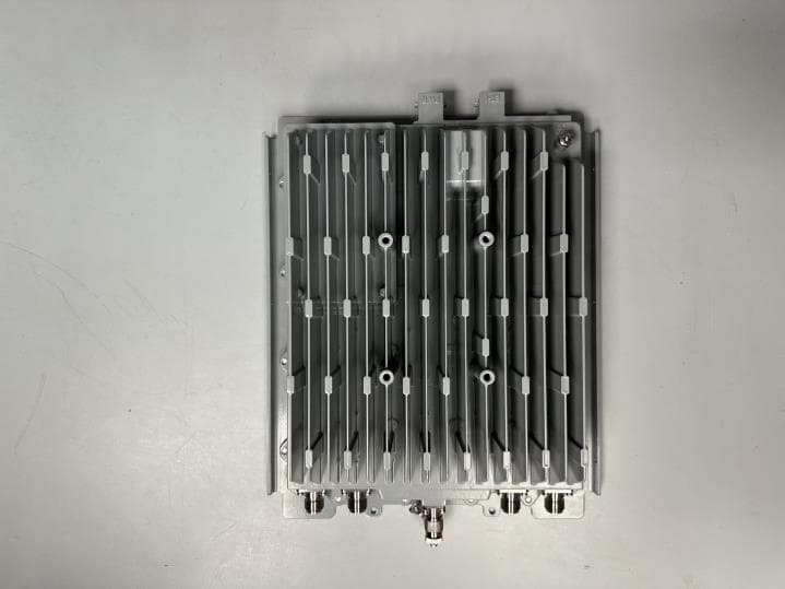
PIDAS1035
Sep 20, 2023LTE Base Station
Equipment Class
TNB - Licensed Non-Broadcast Station Transmitter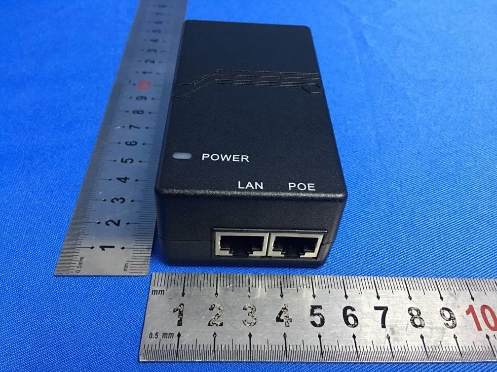
PIDASPOT5410
Jan 10, 2021B42H/B43L/B48
Equipment Class
CBD - Citizens Band Category A and B Devices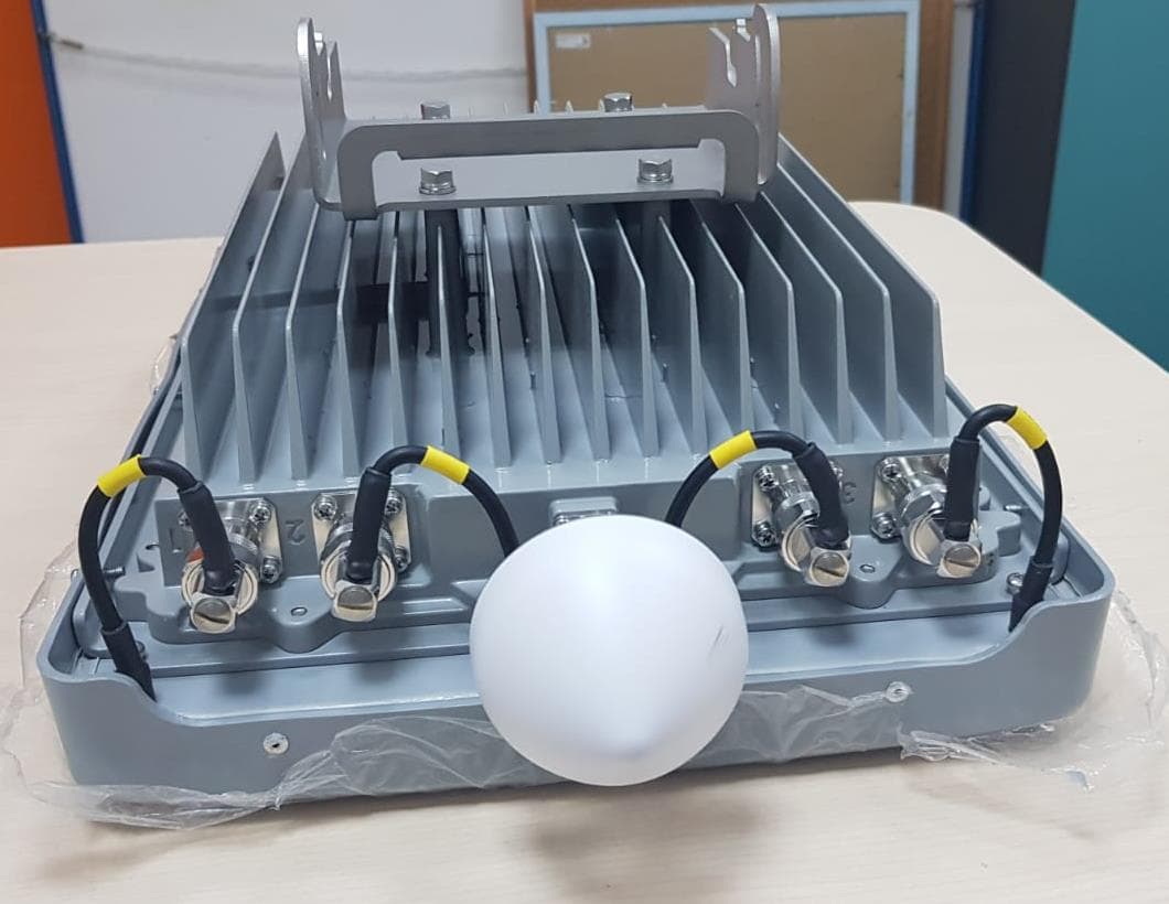
PIDAS1030
Aug 23, 2020LTE Base Station Radio
Equipment Class
CBD - Citizens Band Category A and B Devices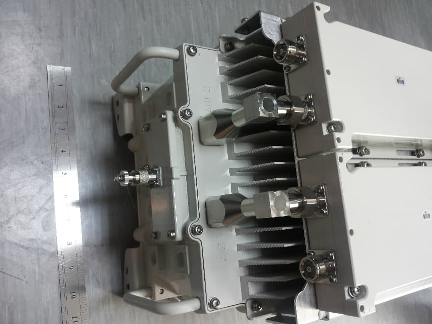
PIDH4K25
Jan 27, 2016Base station of LTE fixed cellular system
Equipment Class
TNB - Licensed Non-Broadcast Station Transmitter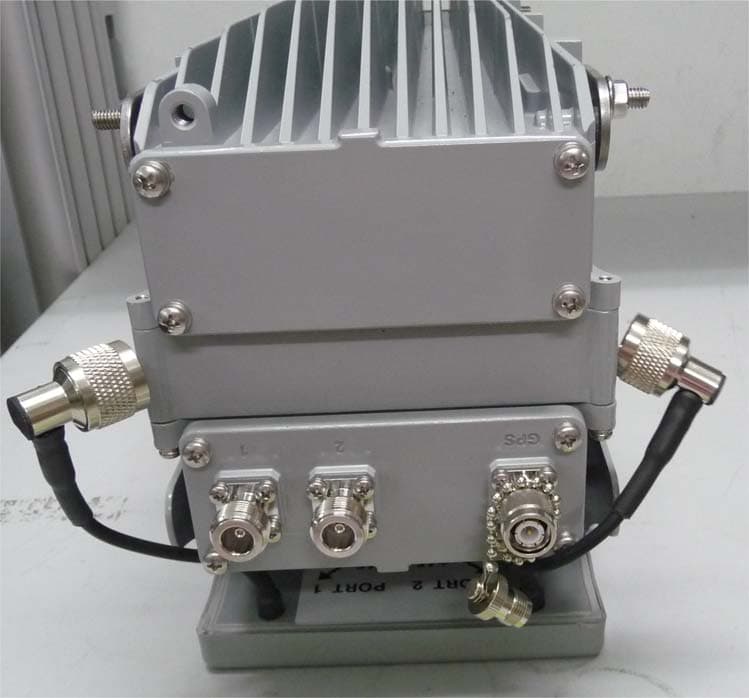
PIDAHR2500
Aug 23, 2015Base station of LTE fixed cellular system
Equipment Class
TNB - Licensed Non-Broadcast Station Transmitter