PIDASMAX3700WiMAX terminal station
Airspan Networks Inc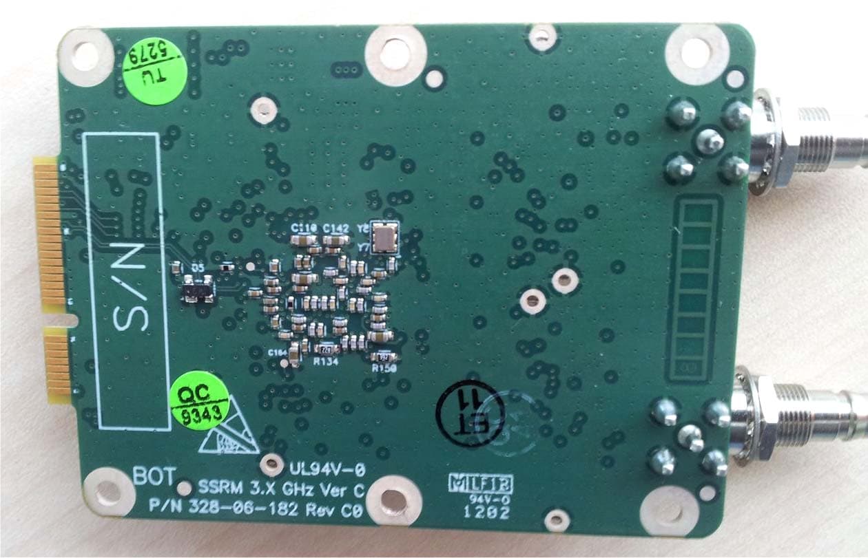
Click to zoom
Application Details
- Equipment Class
- TNB - Licensed Non-Broadcast Station Transmitter
- Date of Grant
- Sep 26, 2012
- Application Purpose
- Original Equipment
- Date of Application
- Jun 19, 2012
- Equipment Note
- WiMAX terminal station
- Frequency Range
- 3655.00000000 - 3695.00000000
- Company
- Airspan Networks Inc
- Country
- United States
Documents & Files
Document Text
Text extracted from the exhibit documents filed with the FCC. Open a document above to read the original.
Users Manual
UGD-D00234 Rev B SSRM Module User Guide System Release 9.7 SSRM Module User Guide Page 2 Commercial in Confidence UWB-D00234 Rev B Acknowledgements Airspan Networks Inc. acknowledges the following trademarks used within this document: © Intel Corporation http://www.intel.com/ © Microsoft Corporation http://www.microsoft.com © SEQUANS COMMUNICATIONS http://www.sequans.com Copyright © Copyright by Airspan Networks Inc., 2012. All rights reserved worldwide. The information contained within this document is proprietary and is subject to all relevant copyright, patent and other laws protecting intellectual property, as well as any specific agreements protecting Airspan Networks Inc. rights in the aforesaid information. Neither this document nor the information contained herein may be published, reproduced or disclosed to third parties, in whole or in part, without the express, prior, written permission of Airspan Networks Inc. In addition, any use of this document or the information contained herein for the purposes other than those for which it is disclosed is strictly forbidden. Airspan Networks Inc. reserves the right, without prior notice or liability, to make changes in equipment design or specifications. Information supplied by Airspan Networks Inc. is believed to be accurate and reliable. However, no responsibility is assumed by Airspan Networks Inc. for the use thereof nor for the rights of third parties which may be effected in any way by the use of thereof. Any representation(s) in this document concerning performance of Airspan Networks Inc. product(s) are for informational purposes only and are not warranties of future performance, either expressed or implied. Airspan Networks Inc. standard limited warranty, stated in its sales contract or order confirmation form, is the only warranty offered by Airspan Networks Inc. in relation thereto. This document may contain flaws, omissions or typesetting errors; no warranty is granted nor liability assumed in relation thereto unless specifically undertaken in Airspan Networks Inc. sales contract or order confirmation. Information contained herein is periodically updated and changes will be incorporated into subsequent editions. If you have encountered an error, please notify Airspan Networks Inc. All specifications are subject to change without prior notice. Product performance figures quoted within this document are indicative and for information purposes only. SSRM Module User Guide Page 3 Commercial in Confidence UWB-D00234 Rev B Table of Contents Acknowledgements .......................................................................................................................... 2 Copyright .......................................................................................................................................... 2 Table of Contents ............................................................................................................................. 3 Summary of Figures ......................................................................................................................... 5 Summary of Tables .......................................................................................................................... 6 Warnings and Cautions .................................................................................................................... 7 Human Exposure to Radio Frequencies ...................................................................................... 7 Radio Interference ........................................................................................................................ 7 Modifications ................................................................................................................................. 7 General ......................................................................................................................................... 7 Disclaimer Statement ................................................................................................................... 7 DECLARATION OF CONFORMITY ................................................................................................. 8 FCC Notice ....................................................................................................................................... 9 Federal Communication Commission Notice ............................................................................... 9 Maximum Output TX Power ........................................................................................................... 10 Antenna Types............................................................................................................................ 10 SSRM Antenna Usage ............................................................................................................. 10 1 About this Guide ....................................................................................................................... 12 1.1 Purpose ................................................................................................................................. 12 1.2 Conventions .......................................................................................................................... 12 2 Overview .................................................................................................................................. 13 2.1 SSRM Frequency Ranges .................................................................................................... 13 2.1.1 Main Features ............................................................................................................... 13 2.2 WiMAX Management ............................................................................................................ 13 2.3 SSRM Block Diagram ...........................................................................................…
Text truncated - open the document above for the full version.
Users Manual
UGD-D00234 Rev C1 SSRM Module User Guide SSRM Module User Guide Page 2 Commercial in Confidence UWB-D00234 Rev C1 Acknowledgements Airspan Networks Inc. acknowledges the following trademarks used within this document: © Intel Corporation http://www.intel.com/ © Microsoft Corporation http://www.microsoft.com © SEQUANS COMMUNICATIONS http://www.sequans.com Copyright © Copyright by Airspan Networks Inc., 2012. All rights reserved worldwide. The information contained within this document is proprietary and is subject to all relevant copyright, patent and other laws protecting intellectual property, as well as any specific agreements protecting Airspan Networks Inc. rights in the aforesaid information. Neither this document nor the information contained herein may be published, reproduced or disclosed to third parties, in whole or in part, without the express, prior, written permission of Airspan Networks Inc. In addition, any use of this document or the information contained herein for the purposes other than those for which it is disclosed is strictly forbidden. Airspan Networks Inc. reserves the right, without prior notice or liability, to make changes in equipment design or specifications. Information supplied by Airspan Networks Inc. is believed to be accurate and reliable. However, no responsibility is assumed by Airspan Networks Inc. for the use thereof nor for the rights of third parties which may be effected in any way by the use of thereof. Any representation(s) in this document concerning performance of Airspan Networks Inc. product(s) are for informational purposes only and are not warranties of future performance, either expressed or implied. Airspan Networks Inc. standard limited warranty, stated in its sales contract or order confirmation form, is the only warranty offered by Airspan Networks Inc. in relation thereto. This document may contain flaws, omissions or typesetting errors; no warranty is granted nor liability assumed in relation thereto unless specifically undertaken in Airspan Networks Inc. sales contract or order confirmation. Information contained herein is periodically updated and changes will be incorporated into subsequent editions. If you have encountered an error, please notify Airspan Networks Inc. All specifications are subject to change without prior notice. Product performance figures quoted within this document are indicative and for information purposes only. SSRM Module User Guide Page 3 Commercial in Confidence UWB-D00234 Rev C1 Table of Contents Acknowledgements .................................................................................................................... 2 Copyright .................................................................................................................................... 2 Table of Contents ....................................................................................................................... 3 Summary of Figures ................................................................................................................... 5 Summary of Tables .................................................................................................................... 6 Warnings and Cautions .............................................................................................................. 7 Human Exposure to Radio Frequencies ...................................................................................... 7 Radio Interference ........................................................................................................................ 7 Modifications ................................................................................................................................ 7 General......................................................................................................................................... 7 Disclaimer Statement ................................................................................................................... 7 DECLARATION OF CONFORMITY .......................................................................................... 8 FCC Notice ............................................................................................................................... 10 Federal Communication Commission Notice ............................................................................. 10 Limitations .................................................................................................................................. 10 Labeling Requirement ................................................................................................................ 10 Maximum Output TX Power ..................................................................................................... 11 Antenna Types ........................................................................................................................... 11 SSRM Antenna Usage ............................................................................................................ 11 1 About this Guide ................................................................................................................ 13 1.1 Purpose ................................................................................................................................ 13 1.2 Conventions .......................................................................................................................... 13 2 Overview ............................................................................................................................ 14 2.1.1 Main Features ............................................................................................................... 14 2.2 WiMAX Management ............................................................................................................ 14 2.3 SSRM Block Diagram ............................…
Text truncated - open the document above for the full version.
Attestation Statements
Airspan Networks Inc. 777 Yamato Rd Suite 310, Boca Raton, Florida, United States, 33431 FCC DECLARATION LETTER FCC ID: PIDASMAX3700 Date: 2012.06.20 To whom it may concern: By SSRM 3.65GHz hardware configuration, the maximum ratio of DL: UL is 31:16. That means it can not support the higher ratio then 31:16. The ratio can not be modified to higher ratio then 31:16 by any method. The device does not support mobile station FDD mode. Sincerely, Brian Roberts Engineering Dept. Airspan Networks Inc. Tel: +1 561 893 8686 Fax: +1 561 893 8671 e-mail: [email protected]
Attestation Statements
protocol for devices operating in the 3650‐3700 MHz Band under Part 90Z Guidance regarding contention based Document Overview This document identifies several questions / information to help determine the contention based protocol capability of a device that may operate in the 3650 – 3700 MHz under part 90Z of our rules. These questions are intended to be used as a guide by the applicant to describe how their system meets the requirements for 3650‐3700 contention based protocol. The list is not intended to be exhaustive and may be modified in the future. There may be follow‐up questions based on the responses provide by the applicant for authorization. Applicants seeking certification for systems as complying with restricted contention based protocol (3650 to 3675 MHz) that permit operation on a co‐channel with like systems (similar systems) may seek equipment authorization from a Telecommunications Certification Body (TCB) using the Permit but Ask procedure as described in Section 3 . Applicants seeking certification for systems as complying with the unrestricted contention based protocol for operation in the 3650 to 3700MHz band that permit operation on a co‐channel with similar or different systems (recognizing other systems) must apply to the FCC for equipment authorization. 1 Restricted Certification under Part 90Z (3650‐3675 Band) In order to ensure that a device complies with the requirements of restricted contention based protocol, the following information should be provided in the application. The product that we will seek approval for is already certified for restricted use. We have therefore only addresses items 2.x. 1.1. Restricted Protocol Description 1.1.1. Although the restricted protocol does not have the extended requirement to recognize all other systems it is still mandatory to incorporate a contention based protocol that provides satisfactory sharing of spectrum with similar systems. 1.1.2. Address the key requirements for operation using restricted contention based protocol opportunities for other transmitters to operate. Please note that this requires recognizing like systems (similar to yours) that permit operation on a co‐channel. 1.1.3. Provide any additional manuals and operational descriptions to allow the reviewer to understand the product and its operation. 1 1/13/2010 3 552295 D01 CBT Guidance for 3650 3700 Band v01r01 1.2 1.3 1.4 Describe the method to permit occupancy Describe the action taken if two or more transmitters simultaneously access the same channel by the master and the client devices. Describe opportunities for other similar systems to operate Address how or if a different system operator using the same technology can operate in the same band. 2 Unrestricted Certification under Part 90Z (3650‐3700 Band) In order to ensure that a device complies with the requirements of unrestricted contention based protocol, the following information should be provided in the application. 2.1. Unrestricted Protocol Description Address the key requirements for operation using unrestricted contention based protocol. Please note that this requires recognizing other systems (both similar to yours and different from yours) that operate on a co‐channel. Indicate the strategy for sharing the spectrum in terms of: Does the system use spectrum sensing to determine if the other devices are transmitting and then find ways to share the bandwidth, or have some other strategy? The base station employs a “listen before transmit” function whose purpose is to detect co‐channel transmissions above a configurable detection threshold. The detection circuitry measures power level irrespective of the transmitting system’s air interface type (ie. technology agnostic). Detection is made at the start of each WiMAX frame (typically every 5 or 10ms). Upon detection of a transmission above the configured threshold, the base station creates a “contention allocation slot” that allows other systems access by creating gaps in it’s transmission (both the BS and associated CPE which is scheduled by the BS). Note that the number of frames over which transmission is stopped is operator configurable (Netspan “carrier Sense backoff Frames”) from a minimum value of 2 frames and the default value is typically 4‐5frames (20‐25ms), but can be much longer. Transmissions continue after the channel is clear (i.e. the other system’s transmissions stop), as the Base Station repeats the detection measurement at regular intervals and adjusts the contention slots accordingly. 2 1/13/2010 3 552295 D01 CBT Guidance for 3650 3700 Band v01r01 2.2. Threshold detection to determine occupancy 2.2.1. Describe how your system determines if another system is using the spectrum. At what detection level – relative to 0 dBi receive antenna gain (busy channel threshold) does the device determine if another system is operating on the spectrum? The base stations transceiver design includes additional circuitry for performing an in‐band interference measurement. This makes measurements of the co‐channel power within allotted “listen” periods at the start of each frame. The power threshold above which a “contention allocation slot” will be triggered is configurable through SNMP commands to the Base Station. Airspan’s element manager software allows the operator to set threshold levels between –65dBm and –96dBm (relative to a 0dBi antenna gain). This is set by the “Carrier Sense Threshold” parameter in the Netspan Management software. 2.2.2. How long does the system observe to determine if the channel is busy – at the initial time and in between communications? The base station makes a measurement every frame (typically 5 or 10ms). The measurement period is 20us. The Base station creates “Contention slots”. These slots are typically 20‐25ms. 2.2.3. What is the bandwidth being monitored versus bandwidth occupied for all modes of operation? The measurement is made over the bandwidth of operation as detection is made after the app…
Text truncated - open the document above for the full version.
Attestation Statements
Page 1 of 1 June 21, 2012 Federal Communication Commission Office of Engineering and Technology USA RE: FCC ID:PIDASMAX3700 Form 731 CN: EA641636 Subject: Files uploaded twice Dear Madam/Sir, 1) Due to our or FCC server malfunction I did not see the Attachment Upload Results information that “Schematic diagram” and “Parts list” files passed, so they were uploaded twice, but they are wholly identical files. 2) Also please disregard “Operational description” file without confidentiality uploaded by mistake and use confidential Correct operational description, as asked in Request for confidentiality. We apologize for any inconvenience caused. Many thanks in advance. Marina Cherniavsky, certification engineer p/p Michael Nikishin, EMC & Radio Group Manager Hermon Laboratories
Attestation Statements
Airspan Interference Detection in Unrestricted FCC Band Guidance regarding contention based protocol for devices operating in the 3650-3700 MHz Band under Part 90Z. Airspan Interference Detection in Unrestricted FCC Band Page 2 1 Document Overview This document identifies several questions / information to help determine the contention based protocol capability of a device that may operate in the 3650 – 3700 MHz under part 90Z of our rules. These questions are intended to be used as a guide by the applicant to describe how their system meets the requirements for 3650-3700 contention based protocol. This device is WiMAX fixed remote terminal station. The base station enables fixed remote terminal station and ensures CBP implementation. In order to start any transmission of WiMAX fixed remote terminal station, it first has to be synchronized with the transmission of the base station. In order to be synchronized with the base station, the terminal station has to detect the preamble transmitted by the base station every frame and to decode the DL and UL MAP messages which are broadcasted by the base station. It then has to verify that the base station identity (BSID), which is broadcasted by the BS matched the BSID that the terminal station is configured to work with. The UL MAP messages contains transmission allocations for the terminals station, therefore, without synchronization to the base station transmission, without validation of the BSID and without decoding of the UL MAP, terminal station is not able to transmit. This device is WiMAX fixed remote terminal station intended for operation with Base station FCC ID: PIDMMAX3605 or Base station FCC ID: O2J-365AS (Airspan’s BS). Answers to FCC Technical questions in KDB 552295 for devices operating in the 3650-3700 MHz Band under Part 90Z. Airspan Interference Detection in Unrestricted FCC Band Page 3 2 Unrestricted Certification under Part 90Z (3650-3700 Band) In order to ensure that a device complies with the requirements of unrestricted contention based protocol, the following information should be provided in the application. 2.1 Unrestricted Protocol Description 2.1.1 Address the key requirements for operation using unrestricted contention based protocol. Please note that this requires recognizing other systems (both similar to yours and different from yours) that operate on a co-channel. Indicate the strategy for sharing the spectrum in terms of: Does the system use spectrum sensing to determine if the other devices are transmitting and then find ways to share the bandwidth, or have some other strategy? The base station employs a “listen before transmit” function whose purpose is to detect co-channel transmissions above a configurable detection threshold. The detection circuitry measures power level irrespective of the transmitting system’s air interface type (i.e. technology agnostic). Detection is made at the start of each WiMAX frame (typically every 5 or 10ms). Upon detection of a transmission above the configured threshold, the base station creates a “contention allocation slot” that allows other systems access by creating gaps in it’s transmission (both the BS and associated CPE which is scheduled by the BS). Note that the number of frames over which transmission is stopped is operator configurable (Netspan “carrier Sense backoff Frames”) from a minimum value of 2 frames and the default value is typically 4-5 frames (20-25ms), but can be much longer. Transmissions continue after the channel is clear (i.e. the other system’s transmissions stop), as the Base Station repeats the detection measurement at regular intervals and adjusts the contention slots accordingly. 2.2 Threshold Detection to Determine Occupancy 2.2.1 Describe how your system determines if another system is using the spectrum. At what detection level – relative to 0 dBi receive antenna gain (busy channel threshold) does the device determine if another system is operating on the spectrum? The base stations transceiver design includes additional circuitry for performing an in-band interference measurement. This makes measurements of the co-channel power within allotted “listen” periods at the start of each frame. The power threshold above which a “contention allocation slot” will be triggered is configurable through SNMP commands to the Base Station. Airspan’s element manager software allows the operator to set threshold levels between –65dBm and –96dBm (relative to a 0dBi antenna gain). This is set by the “Carrier Sense Threshold” parameter in the Netspan Management software. 2.2.2 How long does the system observe to determine if the channel is busy – at the initial time and in between communications? The base station makes a measurement every frame (typically 5 or 10ms). The measurement period is 20us. The Base station creates “Contention slots”. These slots are typically 20-25ms. 2.2.3 What is the bandwidth being monitored versus bandwidth occupied for all modes of operation? The measurement is made over the bandwidth of operation as detection is made after the appropriate channel bandwidth filter. 2.2.4 How much variability is provided to the system operator to adjust busy channel detection threshold? The normal operating receive threshold varies depending upon the modulation and coding scheme that the CPE is using. This will range from approx. -96dBm and -70dBm for low and high order modulations respectively. The operator has no control over the upper level and we therefore regard the maximum operating receive threshold to be around -70dBm. To provide the operator with some margin whilst ensuring that the threshold cannot be set at a level that might prevent the system from operating “fairly”, the maximum level that can be set by the operator is limited by the Netspan Airspan Interference Detection in Unrestricted FCC Band Page 4 Management software to -65dBm. Hence, the operator can set threshold levels between -65dBm and -96dBm (relative to a 0dBi antenna gai…
Text truncated - open the document above for the full version.
Cover Letter(s)
Airspan Networks Inc. 777 Yamato Rd Suite 310, Boca Raton, Florida, United States, 33431 FCC ID: PIDASMAX3700 Date: 2012.06.19 FEDERAL COMMUNICATIONS COMMISSION Authorization and Evaluation Division Confidentiality Request Pursuant to Sections 0.457 and 0.459 of the Commission’s Rules, the applicant hereby requests confidential treatment of information accompanying this application as outlined below: Schematics Parts list Tune up procedure Operational description The above materials contain trade secrets and proprietary information not customarily released to the public. The public disclosure of these matters might be harmful to the applicant and provide unjustified benefits to its competitors. The applicant understands that pursuant to Rule 0.457, disclosure of this application and all accompanying documentation will not be made before the date of the grant for this application. Sincerely, Brian Roberts Engineering Dept. Airspan Networks Inc. Tel: +1 561 893 8686 Fax: +1 561 893 8671 e-mail: [email protected]
Cover Letter(s)
Page 1 of 1 Limited single modular transmitter approval request FCC ID:PIDASMAX3700 Items to be covered Answer from applicant The modular transmitter must have its own RF shielding. The modular transmitter has its own RF shielding. The RF shielding consists of the metal shielding of the module cover. The modular transmitter must have buffered modulation/data inputs (if such inputs are provided) to ensure that the module will comply with Part 15 requirements under conditions of excessive data rates or over-modulation. Data from hosting PC to RF module pass thru SQN1210 chip which is used as a data buffer. The modular transmitter must have its own power supply regulation. All power rails on system are regulated and/or filtered (pi filter) on board before entering the modular transmitter. As a module is inserted into a standard Host slot the EUT is powered by the 5.4 VDC The modular transmitter must comply with the antenna requirements of Section 15.203 and 15.204(c). The antenna must either be permanently attached or employ a “unique” antenna coupler (at all connections between the module and the antenna, including the cable). Antennas in use are a unique Directional Panel Antenna 19.5 dBi and Monopole 5.6 dBi requiring professional installation only. As noted in the User manual. The modular transmitter must be tested in a stand-alone configuration, i.e., the module must not be inside another device during testing. This is intended to demonstrate that the module is capable of complying with Part 15 emission limits regardless of the device into which it is eventually installed. The Tx module was tested in stand-alone con- figuration connected with 15 cm cable to evaluation board. The cable was decoupled with ferrite at approximately 2 cm to represent the actual in slot installation. As a module, the EUT must be inserted directly into a Mini PCIe slot. The modular transmitter must be labeled with its own FCC ID number, and, if the FCC ID is not visible when the module is installed inside another device, then the outside of the device into which the module is installed must also display a label referring to the enclosed module. This exterior label can use wording such as the following: “Contains Transmitter Module FCC ID: XYZMODEL1” or “Contains FCC ID: XYZMODEL1.” Any similar wording that expresses the same meaning may be used. The Grantee may either provide such a label, an example of which must be included in the application for equipment authorization, or, must provide adequate instructions along with the module which explain this requirement. In the latter case, a copy of these instructions must be included in the application for equipment authorization. The modular transmitter has its own FCC ID: PIDASMAX3700. If the FCC ID is not visible when the module is installed inside another device, user has the instructions to apply a FCC ID label on the other device (referred to in page 9 of the User manual). The modular transmitter must comply with any specific rule or operating requirements applicable to the transmitter and the manufacturer must provide adequate instructions along with the module to explain any such requirements. A copy of these instructions must be included in the application for equipment authorization. There is no specific rule or operating requirements applicable to the transmitter with respect to user operation. The modular transmitter must comply with any applicable RF exposure requirements. Modular transmitters approved under other Sections of Part 15, when necessary, may also need to address certain RF Exposure concerns, typically by provi…
Text truncated - open the document above for the full version.
Contact Information
Applicant
Grant Pottash(Technical Services Director)
Technical Contact
Hermon Laboratories Ltd.Michael Nikishin
[email protected]+972 4626 8440
Harakevet Industrial zone · Binyamina · Israel
Non-Technical Contact
Airspan Networks Inc.Zion Levi
[email protected]+1 561 893 8686
Test Firm
Hermon Laboratories Ltd.Alexander Usoskin
Technical Specifications
| # | Rule Parts | Frequency Range | Power Output | Emission | Tolerance |
|---|---|---|---|---|---|
| 2 | 9 | 3.65 GHz - 3.69 GHz | 8.13 W | 10M0D7D | 3678 Hz |
Other Applications from Airspan Networks Inc
PIDAS1035
Sep 20, 2023LTE Base Station
Equipment Class
TNB - Licensed Non-Broadcast Station Transmitter
PIDASPOT5410
Jan 10, 2021B42H/B43L/B48
Equipment Class
CBD - Citizens Band Category A and B Devices
PIDAS1030
Aug 23, 2020LTE Base Station Radio
Equipment Class
CBD - Citizens Band Category A and B Devices
PIDH4K25
Jan 27, 2016Base station of LTE fixed cellular system
Equipment Class
TNB - Licensed Non-Broadcast Station Transmitter
PIDAHR2500
Aug 23, 2015Base station of LTE fixed cellular system
Equipment Class
TNB - Licensed Non-Broadcast Station Transmitter