PIDMARCONIWireless Local Loop System
Airspan Networks Inc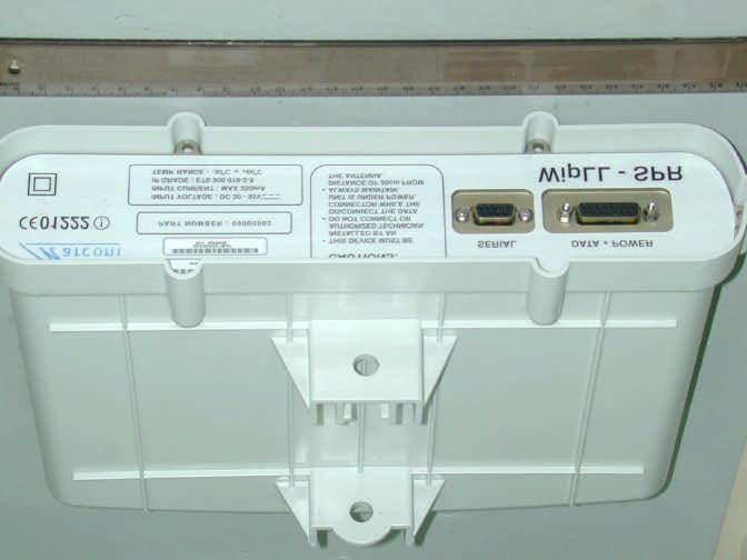
Click to zoom
Application Details
- Equipment Class
- DSS - Part 15 Spread Spectrum Transmitter
- Date of Grant
- Apr 15, 2001
- Application Purpose
- Original Equipment
- Date of Application
- Apr 15, 2001
- Equipment Note
- Wireless Local Loop System
- Frequency Range
- 2402.00000000 - 2480.00000000
- Company
- Airspan Networks Inc
- Country
- United States
Documents & Files
Document Text
Text extracted from the exhibit documents filed with the FCC. Open a document above to read the original.
Users Manual
WipLL WipLLWipLL WipLL Wireless IP-Based Local Loop System Release 2.0 WipLL System Description MCIL-WIPLL-SDN_R2_00 This product is marked with a CE Mark (see below). This mark has been affixed to demonstrate full product compliance with the following European directives: a) Directive 73/23/EEC - Council Directive of 19/02/1973 on the harmonization of the laws of Member States relating to electrical equipment designed for use within certain voltage limits. b) Directive 89/336/EEC - Council Directive of 3/05/1989 on the approximation of laws of the Member States relating to Electro-Magnetic Compatibility (EMC). Issue Date: 2-Apr-01 Revision Record: WipLL System Description Pub. Rev. Date Update Description 1.2 Nov-00 First edition and printing. Author: MCIL 1.4 Mar-01 WipLL Release 1.4 Issue 02 2.0 Apr-01 WipLL Release 2.0 Issue 01 Publication No. MCIL-WIPLL-SDN_R2_00 Copyright by MARCONI COMMUNICATIONS LTD, 2001. All rights reserved worldwide. The information contained in this document is proprietary and is subject to all relevant copyright, patent and other laws protecting intellectual property, as well as any specific agreement protecting MARCONI COMMUNICATIONS LTD. rights in the aforesaid information. Neither this document nor the information contained herein may be published, reproduced or disclosed to third parties, in whole or in part, without the express, prior, written permission of MARCONI COMMUNICATIONS LTD. In addition, any use of this document or the information contained herein for any purposes other than those for which it was disclosed is strictly forbidden. MARCONI COMMUNICATIONS LTD. reserves the right, without prior notice or liability, to make changes in equipment design or specifications. Information supplied by MARCONI COMMUNICATIONS LTD. is believed to be accurate and reliable. However, no responsibility is assumed by MARCONI COMMUNICATIONS LTD. for the use thereof nor for the rights of third parties which may be effected in any way by the use thereof. Any representation(s) in this document concerning performance of MARCONI COMMUNICATIONS LTD. product(s) are for informational purposes only and are not warranties of future performance, either express or implied. MARCONI COMMUNICATIONS LTD. standard limited warranty, stated in its sales contract or order confirmation form, is the only warranty offered by MARCONI COMMUNICATIONS LTD. in relation thereto. This document may contain flaws, omissions or typesetting errors; no warranty is granted nor liability assumed in relation thereto unless specifically undertaken in MARCONI COMMUNICATIONS LTD. sales contract or order confirmation. Information contained herein is periodically updated and changes will be incorporated into subsequent editions. If you have encountered an error, please notify MARCONI COMMUNICATIONS LTD. All specifications are subject to change without prior notice. QUESTIONS / COMMENTS If you have questions or comments about this publication, please e-mail to [email protected] Name Company Tel/Fax/e-mail: Publication Name: Catalogue No. My question/comment is: Thank you. Marconi Communications Ltd Marketing Department This page intentionally left blank Contents MCIL-WIPLL-SDN_R2_00 Marconi Communications Ltd. i Contents 1 GENERAL OVERVIEW ............................................................................ 1-1 1.1. Components of the System ........................................................... 1-4 1.1.1. The Subscriber Site ........................................................... 1-5 1.1.2. Base Station Components ................................................. 1-6 1.1.3. Coverage ........................................................................... 1-7 1.2. Management, and Commissioning ................................................ 1-9 1.2.1. WipManage ..................................................................... 1-10 1.2.2. WipConfig........................................................................ 1-10 2 MAIN FEATURES, PROTOCOL AND QoS.............................................. 2-1 2.1. Features........................................................................................ 2-1 2.1.1. User Perspective ............................................................... 2-1 2.1.2. Operator Perspective......................................................... 2-2 2.1.3. Capacity ............................................................................ 2-2 2.1.4. QoS ............................................................................... 2-2 2.1.5. Configuration ..................................................................... 2-3 2.1.6. Installation and Commissioning ......................................... 2-3 2.1.7. Security ............................................................................. 2-3 2.1.8. MAC Protocol .................................................................... 2-3 2.1.9. Radio Communications...................................................... 2-4 2.1.10. Management...................................................................... 2-5 2.1.10.1. Network Management Systems (NMS) ............ 2-5 2.1.11. System Parameters ........................................................... 2-5 2.1.12. RF ............................................................................... 2-5 2.1.13. Network ............................................................................. 2-6 2.1.14. Application ......................................................................... 2-6 WipLL System Description ii Marconi Communications Ltd. MCIL-WIPLL-SDN_R2_00 2.2. PPMA Protocol.............................................................................. 2-6 2.2.1. What is PPMA? ................................................................. 2-7 2.2.1.1. Concept ............................................................. 2-7 2.2.1.2. Slotted Aloha Process........................................ 2-7 2.2.1.3. P…
Text truncated - open the document above for the full version.
Block Diagram
26-Jul -9 8 R. E. SAW SAW - - Rx Rx 20 db Gai n cont rol 40 db Gai n cont rol SAW SAW - - Tx Tx Dat a Cl k Stb PLL GC T/R TGC Dat a Cl k Stb DAC x 8 1-Vtcxo 2-TGC 3-RGC 4-Vcgy121 5-V2126 1Vppon50 O Hm T/R TxPD TxPD Di v T/R Tx Di v T/R T/R VTCXO VTCXO +-20 PPM FrequencyCont rol To PLL 20 db Gai n cont rol TxPD Rx RSSI °C Tem p 6V RGC TGC DAC #5 DAC #1 DAC #3 DAC #2 DAC #4 20M Hz 2050M Hz – 20150M Hz 356M Hz
Cover Letter(s)
Marconi Communications Israel Limited Registered in Israel. No. 51-279477-7 Marconi Communications Israel Ltd 1 Hamlacha St., LOD 71293, Israel T: +972-8-9777000 ; F: +972-8-9777050 www.marconicomms.com American TCB 6731 Whittier Ave Suite C110 McLean, VA 22101 USA Subject: Application for certification of frequency hopping transceiver, model names BSR-2.4 and SPR-2.4, FCC ID:PIDMARCONI Dear Gentlemen, Please find attached our application for certification of frequency hopping transceiver, model names BSR-2.4 and SPR-2.4, FCC ID:PIDMARCONI prepared in accordance with FCC Rules, parts 2 and 15. We apply to you with request to withhold Marconi Communications Ltd. trade secret in Application for Certification for FCC ID: PIDMARCONI. These trade secrets can be found in the BSR-2.4 and SPR-2.4 schematic diagram (5 pages of this Application). The product testing and this application for certification were performed by Hermon Laboratories, which is listed by FCC. Hermon Labs responsibleperson is Dr. Edward Usoskin, tel: 011 972 6628 8001, fax:011 972 6628 8277, e-mail: [email protected] We hope this application satisfies your requirements Sincerely yours Mr. Shmuel Bleichman, VP engineering Marconi Communications Ltd.
Cover Letter(s)
To: Valeria Mednikov Subject: FCC ID: PIDMARCONI Importance: High Valeria, 1.) All Applications for equipment authorization must include an RF exposure evaluation. This is missing. The form of the evaluation can be either a SAR or MPE evaluation. Since this equipment is used on fixed outdoor or indoor locations, MPE would be appropriate. Please show this evaluation for all antennas. Appropriate warnings and installation instructions must be present in the manual. Please address. 2.) Please provide an attestation as to professional installation. See 15.203. 3.) 15.247 (b)(3) allows for operation in excess of the de-facto 4W EIRP limit assuming the device is used exclusively for fixed point to point services. You are rating the equipment as .3W on the 731 form and combined with up to a 15dBi (or 18?) gain antenna. This appears to be against the provision of 15.247(b)((3)(iii). Please explain. 4.) According to your manual, your equipment appears capable of indoor usage. These would qualify, for the purposes of RF exposure evaluation, mobile transmitters. [See 2.1091] Consequently, the total peak conducted and peak radiated EIRP must not exceed 200mW. Please review the attached documents. As a suggestion, it may be most appropriate to separate the outdoor fixed equipment from the "mobile" [i.e. indoor] equipment with a different application. 5.) Section 4.1 of your manual indicates the equipment can operate in TDMA mode. Does this mean the transmitter will sit on one specific frequency? If so, it will not qualify as a spread spectrum radio . 6.) Third party antennas are not permitted unless they are tested and shown in the test report. Ideally, all antennas should be identified by manufacturer and part number or type, and corresponding gain There may be other questions which occur with this application. There is much for me as examinining engineer to understand about this system, and consequently more questions may be forthcoming. Bill ~~~~~~~~~~~~~~~~~~~~~~~~~~~~~~~~ ~ William H. Graff, NARTE Certified ~ President and Director of Engineering ~ AmericanTCB, Inc. ~ 6731 Whittier Ave ~ McLean, VA 22101 ~ mailto:[email protected].) ~ Direct Mobile: (602)790-6788 ~ Corporate Phone: (703)847-4700 ~ Corporate FAX: (703) 847-6888 ~~~~~~~~~~~~~~~~~~~~~~~~~~~~~~~~
Cover Letter(s)
To: Valeria Mednikov Subject: FCC ID: PIDMARCONI Importance: High Valeria, 1.) All Applications for equipment authorization must include an RF exposure evaluation. This is missing. The form of the evaluation can be either a SAR or MPE evaluation. Since this equipment is used on fixed outdoor or indoor locations, MPE would be appropriate. Please show this evaluation for all antennas. Appropriate warnings and installation instructions must be present in the manual. Please address. 2.) Please provide an attestation as to professional installation. See 15.203. 3.) 15.247 (b)(3) allows for operation in excess of the de-facto 4W EIRP limit assuming the device is used exclusively for fixed point to point services. You are rating the equipment as .3W on the 731 form and combined with up to a 15dBi (or 18?) gain antenna. This appears to be against the provision of 15.247(b)((3)(iii). Please explain. 4.) According to your manual, your equipment appears capable of indoor usage. These would qualify, for the purposes of RF exposure evaluation, mobile transmitters. [See 2.1091] Consequently, the total peak conducted and peak radiated EIRP must not exceed 200mW. Please review the attached documents. As a suggestion, it may be most appropriate to separate the outdoor fixed equipment from the "mobile" [i.e. indoor] equipment with a different application. 5.) Section 4.1 of your manual indicates the equipment can operate in TDMA mode. Does this mean the transmitter will sit on one specific frequency? If so, it will not qualify as a spread spectrum radio . 6.) Third party antennas are not permitted unless they are tested and shown in the test report. Ideally, all antennas should be identified by manufacturer and part number or type, and corresponding gain There may be other questions which occur with this application. There is much for me as examinining engineer to understand about this system, and consequently more questions may be forthcoming. Bill ~~~~~~~~~~~~~~~~~~~~~~~~~~~~~~~~ ~ William H. Graff, NARTE Certified ~ President and Director of Engineering ~ AmericanTCB, Inc. ~ 6731 Whittier Ave ~ McLean, VA 22101 ~ mailto:[email protected].) ~ Direct Mobile: (602)790-6788 ~ Corporate Phone: (703)847-4700 ~ Corporate FAX: (703) 847-6888 ~~~~~~~~~~~~~~~~~~~~~~~~~~~~~~~~
Cover Letter(s)
FCC ID:PIDMARCONI, more informationFrom: Marina Chernyavsky [[email protected]] Sent: April 02, 2001 7:57 AM To: '[email protected]' Subject: FCC ID:PIDMARCONI, more information Dear Mr. Graff , Please find below our reply to your second message, dated March 30, 2001 . 1) The RF exposure information as a separate document - attached. Please advise. 2) For the statement about the professional installation and requirement with a separation distance at least 2 meters from all persons during normal operation - please refer to pages 2-3, 2-4, 3-3 of User Manual new version. 3) Our customer MARCONI prefers BSR and SPR to be determined as fixed category outdoor units with 2 m separation distance. Many thanks for your assistance and patience. Best regards , Marina <<RFexposure_information.doc>> <<FCC SysDesc-1.pdf>>
Cover Letter(s)
Dear Mr. Graff, Would you be so kind to accept our partial answer in accordance with your questions. 1) MPE evaluation is included in Test Reports MADRAD_FCC.14534, page 28 for SPR-2.4 and MADRAD_FCC.14551, page 28 for BSR-2.4. In the EUT description, given in page 6 of both test reports, please see, that BSR-2.4 is equipped with 11 dBi internal antenna, SPR-2.4 - with 15 dBi internal antenna. Only these versions were tested and only for these versions Application for Certification was prepared. 2) There is no need in professional installation because only internal antenna is used. Please refer to operational description, external and internal photographs, test reports. 3) As depicted in test reports, pages 27- 28, and User Manual, pages 2-4, 4-7, 6-7, peak output power does not exceed 19 dBm for SPR and 24 dBm for BSR, EIRP does not exceed 34 =19+15 (dBm) for SPR and 24+11=35 dBm for BSR. In Form 731 we gave rated output power .3 W (24 dBm). Should we show EIRP in Form 731? According to page 28 of the test reports the max EIRP is 2710 mW. Please advise. In pages 6-3, 6-4 the 18 dBi antenna is mentioned as “not yet for FCC”, hence this antenna is not used in US applications. Antennas identification is given in Operational Description. Please, again, only flat internal antennas shown in Internal Photos, are used. Third party antennas usage is optional and not for the USA. 4) we recommend to manufacturer to correct User Manual (as you can see - preliminary version) a) to clarify Indoor Coverage, page 3-5; b) to explain clearly, that BSR and SPR are used with one internal antenna only and in no case antenna connectors are used; c) to explain, that 15 dBi antenna in BSR is used only in Europe - page 2-4. 5) we are waiting for the clarification from Marconi. Many thanks in advance for your patience. Best regards, Marina Cherniavsky, Hermon Laboratories certification engineer
External Photos
FCC ID:PIDMARCONI Date: March, 2001 Page 1 of 4 EXTERNAL PHOTOGRAPHS This document contains 3 photographs FCC ID:PIDMARCONI Date: March, 2001 Page 2 of 4 Photograph No.1 BSR-2.4 with SDA general view FCC ID:PIDMARCONI Date: March, 2001 Page 3 of 4 Photograph No.2 BSR-2-4 general view FCC ID:PIDMARCONI Date: March, 2001 Page 4 of 4 Photograph No.3 SPR-2.4 general view
ID Label/Location Info
FCC ID:PIDMARCONI Date: March, 2001 Project number:14534, 14551 Page 1 of 1 LABEL The label shown below is affixed on the bottom of the BSR-2.4 and SPR-2.4 radio units. The label dimensions are 70 x 30 (mm), material - PVC with a permanent adhesive. The FCC part 15, §15.105 statement is placed in User Manual (System Description), page 1-9. Label placement on the EUT bottom Label FCC ID:PIDMARCONI This device complies with Part 15 of the FCC Rules. Operation is subject to the following two conditions: (1) This device may not cause harmful interference, and (2) This device must accept any interference received, including interference that may cause undesired operation.
Internal Photos
FCC ID: PIDMARCONI; BSR-2.4 inside view with covers FCC ID:PIDMARCONI; BSR-2.4 inside view (antenna) FCC ID:PIDMARCONI; BSR-2.4 inside view without covers FCC ID:PIDMARCONI; BSR-2.4 inside view, rear side FCC ID:PIDMARCONI; BSR-2.4 main board front view FCC ID:PIDMARCONI; BSR-2.4 main board rear view FCC ID:PIDMARCONI; BSR-RF2.4 board, printed side FCC ID:PIDMARCONI; BSR-RF2.4 board, component side FCC ID:PIDMARCONI; SPR-2.4 inside view with covers FCC ID:PIDMARCONI; SPR-2.4 inside view (antenna) FCC ID:PIDMARCONI; SPR-2.4 inside view without covers FCC ID:PIDMARCONI; SPR-2.4 inside view, rear side FCC ID:PIDMARCONI; SPR-2.4 main board front view FCC ID:PIDMARCONI; SPR-2.4 main board front view FCC ID:PIDMARCONI; SPR-2.4 main board rear view FCC ID:PIDMARCONI; SPR-RF2.4 board, printed side FCC ID:PIDMARCONI; SPR-RF2.4 board, component side
Operational Description
Marconi Communications Israel Limited Registered in Israel. No. 51-279477-7 Marconi Communications Israel Ltd 1 Hamlacha St., LOD 71293, Israel T: +972-8-9777000 ; F: +972-8-9777050 www.marconicomms.com Subject: Hopping algorithm and compliance with FCC 15.247 (a) (1) 1. Hopping algorithm description The hopping algorithm is defined by a table of n frequencies, when n 75. The hopping sequence follows cyclically the frequencies in the table, staying in each frequency for a constant period. The frequencies note the center frequencies in each hop. Each frequency in the table apearsonce. The frequencies in the table are all in the range 2402- 2482, with at least 1MHz between any two frequencies in the table. The order of frequencies in the table is pseudorandom. 2. Hopping time The hopping time in a given is constant. (typically WipLL uses 50mSec) 3. Number of channels The number of channels is determined by the table size n which is at least 75 (WipLL uses n=79). 4. Resolution The minimum difference between any two channels is 1 MHz. 5. Channel distribution. Since any used channel is included once in the table, all the channels are equally used, each one occupies 1/n of the time. 6. Occupancy time. Each used channel is used once per cycle of n frequencies (n =79 see par. 3 above). The total occupancy time in 30 seconds is: (30sec)/n 0.4sec 30/79 = 0.380 sec. 7. Receiver synchronization. The system receiver input bandwidth filter matches the hopping channel bandwidth and syncronized with the coresponding transmitter on the hopping sequence. 15.247 Spec. Requirement WipLL capability Comply Spread Specrum FHSS or DSSS FHSS yes Channel Separation -20dB bandwidth (1MHz) -20 dB bandwidth (1MHz) yes List of Freq. Pseudo random ordered list. Pseudo random ordered list yes Use of Freq. Equal use of Freq. Constant hop period (50mS) each freq. used once in table. yes Frequency band 2400- 2483.5MHz 2402 – 2482MHz yes Number of frequencies Min. 75 79 yes Occupied BW per hop <1MHz at –20dB <1MHz at –20dB yes Average time of occupancy <0.4 sec see within 30 sec period- average. 0.33 sec within 30sec – average. yes Shmuel Bleichman
RF Exposure Info
FCC ID:PIDMARCONI Date: March, 2001 Project number:14534, 14551 Page 1 of 1 RF exposure information for BSR-2.4 and SPR-2.4 frequency hopping transceivers, operating in 2.402 – 2.480 GHz frequency band MPE limit for power density for general population/uncontrolled exposure according to FCC §1.1310 is 1 mW/cm 2 . P T A power density P (mW/cm 2 ) = ------------- , where 4π r 2 P T - transmitted power. For SPR-2.4: P T is equal to transmitter output power 18.67 dBm plus maximum antenna gain 15 dBi, the maximum equivalent isotropically radiated power (e.i.r.p.) is 34 dBm = 2512 mW. 1(mW/cm 2 ) = 2512 mW / 4π r 2 Allowed distance “r”, where RF exposure limits may not be exceeded, is 14.1 cm: r = √ P T / 4π = √ 2512/ 4 x 3.14 = 14.1 (cm). Public cannot be exposed to dangerous RF level. For BSR-2.4: P T is equal to transmitter output power 23.33 dBm plus maximum antenna gain 11 dBi, the maximum equivalent isotropically radiated power (e.i.r.p.) is 34.33 dBm = 2710 mW. 1(mW/cm 2 ) = 2710 mW / 4π r 2 Allowed distance “r”, where RF exposure limits may not be exceeded, is 14.7 cm: r = √ P T / 4π = √ 2710/ 4 x 3.14 = 14.7(cm). Public cannot be exposed to dangerous RF level.
RF Exposure Info
FCC ID:PIDMARCONI Date: March, 2001 Project number:14534, 14551 Page 1 of 1 RF exposure information for BSR-2.4 and SPR-2.4 frequency hopping transceivers, operating in 2.402 – 2.480 GHz frequency band MPE limit for power density for general population/uncontrolled exposure according to FCC §1.1310 is 1 mW/cm 2 . P T A power density P (mW/cm 2 ) = ------------- , where 4π r 2 P T - transmitted power. For SPR-2.4: P T is equal to transmitter output power 18.67 dBm plus maximum antenna gain 15 dBi, the maximum equivalent isotropically radiated power (e.i.r.p.) is 34 dBm = 2512 mW. 1(mW/cm 2 ) = 2512 mW / 4π r 2 Allowed distance “r”, where RF exposure limits may not be exceeded, is 14.1 cm: r = √ P T / 4π = √ 2512/ 4 x 3.14 = 14.1 (cm). Public cannot be exposed to dangerous RF level. For BSR-2.4: P T is equal to transmitter output power 23.33 dBm plus maximum antenna gain 11 dBi, the maximum equivalent isotropically radiated power (e.i.r.p.) is 34.33 dBm = 2710 mW. 1(mW/cm 2 ) = 2710 mW / 4π r 2 Allowed distance “r”, where RF exposure limits may not be exceeded, is 14.7 cm: r = √ P T / 4π = √ 2710/ 4 x 3.14 = 14.7(cm). Public cannot be exposed to dangerous RF level.
RF Exposure Info
FCC ID:PIDMARCONI Date: March, 2001 Project number:14534, 14551 Page 1 of 1 RF exposure information for BSR-2.4 and SPR-2.4 frequency hopping transceivers, operating in 2.402 – 2.480 GHz frequency band MPE limit for power density for general population/uncontrolled exposure according to FCC §1.1310 is 1 mW/cm 2 . P T A power density P (mW/cm 2 ) = ------------- , where 4π r 2 P T - transmitted power. For SPR-2.4: P T is equal to transmitter output power 18.67 dBm plus maximum antenna gain 15 dBi, the maximum equivalent isotropically radiated power (e.i.r.p.) is 34 dBm = 2512 mW. 1(mW/cm 2 ) = 2512 mW / 4π r 2 Allowed distance “r”, where RF exposure limits may not be exceeded, is 14.1 cm: r = √ P T / 4π = √ 2512/ 4 x 3.14 = 14.1 (cm). Public cannot be exposed to dangerous RF level. For BSR-2.4: P T is equal to transmitter output power 23.33 dBm plus maximum antenna gain 11 dBi, the maximum equivalent isotropically radiated power (e.i.r.p.) is 34.33 dBm = 2710 mW. 1(mW/cm 2 ) = 2710 mW / 4π r 2 Allowed distance “r”, where RF exposure limits may not be exceeded, is 14.7 cm: r = √ P T / 4π = √ 2710/ 4 x 3.14 = 14.7(cm). Public cannot be exposed to dangerous RF level.
Test Report
Test Report: MARRAD_FCC.14534.doc Date: March, 2001 Page 1 of 75 HERMON LABORATORIES ELECTROMAGNETIC EMISSIONS TEST REPORT according to FCC Part 15 subpart C, §15.247 and subpart B for Marconi Communications LTD. EQUIPMENT UNDER TEST: Subscriber Premises Radio Unit of Wireless Local Loop System (WipLL), model SPR-2.4 Hermon Laboratories Ltd. P.O.Box 23 Binyamina 30550, Israel Tel.+972-4628-8001 Fax.+972-4628-8277 Email:[email protected] Electrical Test Report: MARRAD_FCC.14534.doc Date: March, 2001 Page 2 of 75 HERMON LABORATORIES Description of equipment under test Test items Subscriber premises radio unit (frequency hopping transmitter) Manufacturer Marconi Communications Ltd. Types (Models) SPR-2.4 Receipt date February 19, 2001 Applicant information Applicant’s representative & responsible person Mr. Shmuel Bleichman, VP engineering Company Marconi Communications Ltd. Address 1 Hamelacha street Postal code 71293 City Lod Country Israel Telephone number +972 8977 7015 Telefax number +972 8977 7050 Test performance Project Number: 14534 Location Hermon Laboratories Test performed February 19 to February 28, 2001 Purpose of test EUT certification according to FCC requirements Test specification(s) FCC Part 15, subpart C, §15.247, §§15.205, 15.207, 15.209, subpart B §§15.107, 15.109 Test Report: MARRAD_FCC.14534.doc Date: March, 2001 Page 3 of 75 HERMON LABORATORIES Table of Contents 1 SUMMARY AND SIGNATURES..........................................................................................4 2 GENERAL INFORMATION..................................................................................................5 3 TEST FACILITY DESCRIPTION..........................................................................................8 4 EMISSION MEASUREMENTS...........................................................................................10 APPENDIX A – TEST EQUIPMENT AND ANCILLARIES USED FOR TESTS.........................73 APPENDIX B-TEST EQUIPMENT CORRECTION FACTORS..................................................74 Test Report: MARRAD_FCC.14534.doc Date: March, 2001 Page 4 of 75 HERMON LABORATORIES 1 Summary and signatures The EUT, SPR-2.4 base station radio unit, was tested according to FCC part 15 subpart C, §.15.247, subpart B §§15.107, 15.109 and found to comply with the standard requirements. Test performed by: Mrs. E. Pitt, test engineer ________________________ Test report prepared by: Mrs. M. Cherniavsky, certification engineer ________________________ Test report approved by: Mr. M. Nikishin, EMC group leader ________________________ Dr. E. Usoskin, C.E.O. ________________________ The A2LA logo endorsement applies only to the test methods and the standards that are listed in the scope of Hermon Laboratories accreditation by A2LA. Through this report period is used as decimal separator while thousands are separated by comma. This report is in conformity with EN 45001 and ISO GUIDE 25. The test results relate only to the items tested. This test report must not be reproduced in any form except in full, with the approval of Hermon Labs Ltd. Test Report: MARRAD_FCC.14534.doc Date: March, 2001 Page 5 of 75 HERMON LABORATORIES 2 General information 2.1 Abbreviations and acronyms The following abbreviations and acronyms are applicable to this test report: AC alternating current AF antenna factor AVRG average (detector) BER bit error rate BSDU base station distribution unit BW bandwidth CE conducted emissions CL cable loss cm centimeter CW sine wave dB decibel dBm decibel referred to one milliwatt dB(μA) decibel referred to one microampere dB(μV) decibel referred to one microvolt dB(μV/m) decibel referred to one microvolt per meter DC direct current EMC electromagnetic compatibility EUT equipment under test FSK frequency shift keying Gamp amplifier gain GHz gigahertz H height HL Hermon Laboratories Hz hertz IF Intermediate frequency kHz kilohertz L length LO local oscillator m meter Mbps megabit per second mm millimeter MHz megahertz msec millisecond NA not applicable NARTE National Association of Radio and Telecommunications Engineers, Inc. nF nanofarad Ω ohm QP quasi-peak (detector) PC personal computer RBW resolution bandwidth RF radio frequency RE radiated emission sec second SPR subscriber premises radio TDMA time division multiple access V volt V/m volt per meter W watt Test Report: MARRAD_FCC.14534.doc Date: March, 2001 Page 6 of 75 HERMON LABORATORIES 2.2 Specification references CFR 47 part 15:1999 Radio Frequency Devices. ANSI C63.2:1996 American National Standard for Instrumentation- Electromagnetic Noise and Field Strength, 10 kHz to 40 GHz-Specifications. ANSI C63.4:1992 American National Standard for Methods of Measurement of Radio-Noise Emissions from Low- Voltage Electrical and Electronic Equipment in the Range of 9 kHz to 40 GHz. 2.3 EUT description A subscriber premises radio, SPR-2.4, is a part of a broadband fixed cellular wireless access system WipLL. The system provides a radio link between the end-user of the telecom network (the subscriber) and the network itself to give high-speed data access. The EUT is an outdoor unit comprising a frequency hopping transceiver that transmits and receives data to and from the base station. The FSK type of modulation with 1 Mbps data rate is used The transceiver operates in 2402 MHz to 2480 MHz frequency range and is equipped with a 15 dBi gain directional internal antenna. At the network layer, the SPR performs routing functions between the subscriber’s Ethernet network and wireless network, and contains a routing table that can support up to 16 entries. The capacity of each SPR is up to 3 MBps. The SPR is connected to a subscriber data adapter (SDA), which provides 48 V DC power. Test Report: MARRAD_FCC.14534.doc Date: March, 2001 Page 7 of 75 HERMON LABORATORIES 2.4 EUT test configuration The EUT test configuration is given in Figure 2.4.1. Throughout the testing the EUT was powered via SDA. To withstand the stan…
Text truncated - open the document above for the full version.
Test Report
2402 2405 2408 2411 2414 2417 2420 2423 2426 2425 2428 2431 2434 2437 2440 2443 2446 2449 2464 2467 2470 2473 2476 2479 2403 2406 2409 2410 2413 2416 2419 2422 2425 2428 2431 2434 2445 2448 2451 2454 2457 2460 2463 2466 2469 2418 2421 2424 2427 2430 2433 2436 2439 2442 2473 2476 2479 2403 2406 2409 2412 2415 2418 2449 2452 2455 2458 2461 2464 2467 2470 2473 2421 2424 2427 2430 2433 2436 2439 2442 2445 2463 2466 2469 2472 2475 2478 2402 2405 2408 2478 2402 2405 2408 2411 2414 2417 2420 2423 2431 2434 2437 2440 2443 2446 2449 2452 2455 2461 2464 2467 2470 2473 2476 2479 2403 2406 2424 2427 2430 2433 2436 2439 2442 2445 2448 2454 2457 2460 2463 2466 2469 2472 2475 2478 2465 2468 2471 2474 2477 2480 2404 2407 2410 2428 2431 2434 2437 2440 2443 2446 2449 2452 2479 2403 2406 2409 2412 2415 2418 2421 2424 2433 2436 2439 2442 2445 2448 2451 2454 2457 2404 2407 2410 2413 2416 2419 2422 2425 2428 2420 2423 2426 2429 2432 2435 2438 2441 2444 2413 2416 2419 2422 2425 2428 2431 2434 2437 2438 2441 2444 2447 2450 2453 2456 2459 2462 2474 2477 2480 2404 2407 2410 2413 2416 2419 2456 2459 2462 2465 2468 2471 2474 2477 2480 2471 2474 2477 2480 2404 2407 2410 2413 2416 2423 2426 2429 2432 2435 2438 2441 2444 2447 2405 2408 2411 2414 2417 2420 2423 2426 2429 2439 2442 2445 2448 2451 2454 2457 2460 2463 2412 2415 2418 2421 2424 2427 2430 2433 2436 2436 2439 2442 2445 2448 2451 2454 2457 2460 2468 2471 2474 2477 2480 2404 2407 2410 2413 2…
Text truncated - open the document above for the full version.
Contact Information
Applicant
Grant Pottash(Technical Services Director)
Technical Contact
Hermon LaboratoriesDr. Edward Usoskin
[email protected]011 972 4628 8011
P.O.B. 32 · Binyamina · Israel
Non-Technical Contact
Marconi Communications Ltd.Shmuel Bleichman
[email protected]011 972 8977 7015
Test Firm
Hermon Laboratories Ltd.Alexander Usoskin
Technical Specifications
| # | Rule Parts | Frequency Range | Power Output |
|---|---|---|---|
| 1 | 15C | 2.40 GHz - 2.48 GHz | 215.00 mW |
Other Applications from Airspan Networks Inc
PIDAS1035
Sep 20, 2023LTE Base Station
Equipment Class
TNB - Licensed Non-Broadcast Station Transmitter
PIDASPOT5410
Jan 10, 2021B42H/B43L/B48
Equipment Class
CBD - Citizens Band Category A and B Devices
PIDAS1030
Aug 23, 2020LTE Base Station Radio
Equipment Class
CBD - Citizens Band Category A and B Devices
PIDH4K25
Jan 27, 2016Base station of LTE fixed cellular system
Equipment Class
TNB - Licensed Non-Broadcast Station Transmitter
PIDAHR2500
Aug 23, 2015Base station of LTE fixed cellular system
Equipment Class
TNB - Licensed Non-Broadcast Station Transmitter