PIN-PNAV3550PNP
Hyundai MOBIS Co., Ltd.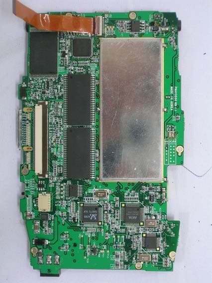
Click to zoom
Application Details
- Equipment Class
- JBP - Part 15 Class B Computing Device Peripheral
- Date of Grant
- Jun 25, 2005
- Application Purpose
- Original Equipment
- Date of Application
- Jun 25, 2005
- Equipment Note
- PNP
- Company
- Hyundai MOBIS Co., Ltd.
- Country
- South Korea
Documents & Files
Document Text
Text extracted from the exhibit documents filed with the FCC. Open a document above to read the original.
Users Manual
Hyundai Autonet Jupiter English Manual PNAV-3550 User’s Manual Thank you for purchasing the PONTUS navigation product. This user’s manual explains detailed methods of use regarding our product. For safety and efficiency, make certain to become familiarized with the contents of this manual before using this product. <FIG 1> Logo Screen CONTENTS Chapter 1 Product Information 1. Product Introduction 2. Make certain to read before use 3. Caution when handling the CD Chapter 2 Before use 1. What is included in the box 2. Names of each section Chapter 3 Installation 1. Car Installation Chapter 4 . Screen Explanation by each Mode and Basic Directions 1.NAVI Mode 2 AUDIO Mode 3 VIDEO Mode 4 PHOTO Mode 5 RECORD Mode 6. SD CARD Mode 7 Environment Setting Chapter 5 Miscellaneous Issues 1. Data Upload & Download Methods Between a Computer and PNAV-3550 2. Upgrading Method for the System Palm ware February 5, 2005 1 Hyundai Autonet Jupiter English Manual 3. Troubleshooting 4. Product Specifications 5. Technical Support & Product Warranty Chapter 1 Product Information 1. Product Introduction 2. Make certain to read before use 3. Caution when handling the CD 1. Product Information This product is a car navigation with MP3 player system. It is designed to be installed and used in vehicle. A GPS engine and an antenna have been mounted for car navigation along with an accurate digital map. The user manual for this product may change without prior notification and affect performance improvement. We ask for your understanding when actual conditions vary due to this reason. The screen in this user’s manual may appear different than the actual screen . Strictly abide to the warning/caution/prohibited regulations stated within this user’s manual for maximum driver and user safety and to prevent property damage. 2. Make certain to read before use. [Abiding traffic regulations] The digital map used in this product has been produced using the most recent road conditions. However, certain information regarding actual conditions of roads and buildings may not yet have been included or may have changed after the release of the product, so it is recommended that the user drive while abiding actual road conditions and traffic regulations. <Caution> No damages or claims will be awarded for any accidents which occurred while not abiding actual road and traffic conditions. This product should only be used as an additional reference. February 5, 2005 2 Hyundai Autonet Jupiter English Manual [Understanding GPS] GPS used for commercial purposes will carry a distance error, on average, of 15 meters(convert to feet). In addition, the distance error reading when close to buildings, underpasses, overpasses, and others may be up to 100 meters(convert to feet). Please take this into consideration during use. [Warnings] - Do not install the device on top of the vehicle’s airbag. If an accident occurs, the movement of the airbag may cause this product to harm the user. - Do not operate while driving. Operating while driving may cause traffic accidents due to lack of caution in gauging upcoming road conditions. When requiring route settings or other operations, be sure to stop and activate the parking brake before such use. -Do not continuously watch the screen. Watching the screen for prolonged periods while driving is very dangerous. Use this device safely as not to prevent oneself from fully understanding real traffic conditions or from seeing pedestrians. -Do not use this device if there are signs of malfunction. Continuous use while there are symptoms of malfunction, such as strange smells and sounds, may cause fires and other damage. In such cases, turn off the power and inquire with your place of purchase. [Caution] - Be cautious not to introduce foreign substances inside the device. Water, beverages, and other foreign substances may cause damages to this product. -Do not cause excessive force. Excessive force may cause damages to this product. -Use in moderate volume levels. Do not receive voice guidance in high volume levels which deter you from understanding the road conditions outside of the vehicle. -Route/Voice Guidance may be different from actual road conditions. Practice safe driving by abiding to actual road regulations as route/voice guidance may be different from actual road conditions. -Satellite reception may require a long period of time. A certain period of time is required for initial GPS satellite reception from the time of powering the unit. Weather and surrounding conditions may cause differences in the required time period. -Operate cautiously after leaving the device in high or low temperature locations. Abnormal operations may occur upon use after prolonged parking periods in locations with severe temperature changes. Please begin use after achieving normal internal temperatures inside of the vehicle. February 5, 2005 3 Hyundai Autonet Jupiter English Manual (Normal operating temperature: 32~131F) [Prohibited] -Do not use the device for long periods of time with the engine turned off. Prolonged use with the ignition off may cause the battery to discharge. -Do not apply metal window tint. Applying strong window tint to the window area in which the GPS Antenna is installed may cause instability in GPS data reception or errors. -Do not place metal substances near the GPS Antenna. Placing metal substances near the area in which the GPS Antenna is installed may deter performance in GPS data reception. -Do not use the device alongside products which emit radio frequencies or with other similar GPS devices. Products which emit radio frequencies or other GPS products may have an effect on this device. Limit simultaneous use as these types of devices may cause deterred GPS reception performance. -Do not disassemble, repair, or modify the device. Damage caused by disassembling, repairing, or modifying may cause fires and accidents and cannot allow reception after service repair. In cases when requiring repair, pl…
Text truncated - open the document above for the full version.
Block Diagram
ARM CPU I/F <CY7C68300> USB 2.0 Device I/F <CN7> External USB Host Connector <SDRAM> 32Mbyte x4 <Flash RAM> 64Mbyte <TVP5150> External Video Decoder I/F <CN9> Internal 20G Hard Disk Connector <SW2> TV Output/Hold/ LCD Output Select Switch <TPS2051> External USB Device Power I/F <CN12> External Cradle Connector <PIC12F675> Main Power/ Reset Control I/F <TPS3806> Battery Power Detection I/F <SW1> Power On/Off Switch <SW3> Reset Switch <AK8813> Video Encoder I/F <ALC650> Audio Codec I/F <CN5> Internal Stereo Audio Output Connector <CN11> Internal A/V Output Connector <LM4861> OP-AMP I/F for Audio <CN1> Internal Key/Speaker Connector <CN3> Internal LCD Connector <AD7843> Touch-Screen Control I/F <CN2> Internal Touch Panel Connector <CN4> GPS Module Connector <CN8> External SD Card Connector <MAX1874> Battery Charger I/F <MAX1556> 3.3V DC-DC Converter I/F <MAX1556> 3.3V DC-DC Coverter I/F <MAX1818> 1.8V Regulator I/F <CN6> Internal Battery Connector <CN10> External AC Adapter Connector <LM8262> <MAX1779> LCD Power I/F <SC4501> LCD Back-light Control I/F <MAX1818> 3.3V Regulator I/F Main Power Block Diagram PNAV-3550 Block Diagram
External Photos
Test report Our reference : KEL05-F05060 Page : B1 of Appendix Issued date : 2005-06-17 Appendix-B : External Photographs of E.U.T <FRONT VIEW OF EUT> Korea EMC Laboratory <REAR VIEW OF EUT>
ID Label/Location Info
Test report Our reference : KEL05-F05060 Page : D1 of Appendix Issued date : 2005-06-17 Appendix-D : FCC ID label location information and Sample - FCC ID label location information The label included following statement will be attached on the rear side of product. - FCC ID label sample Korea EMC Laboratory
Internal Photos
Test report Our reference : KEL05-F05060 Page : C1 of Appendix Issued date : 2005-06-17 Appendix-C : Internal Photographs of E.U.T <INTERNAL VIEW OF E.U.T> Korea EMC Laboratory Test report Our reference : KEL05-F05060 Page : C2 of Appendix Issued date : 2005-06-17 <FRONT VIEW OF BATTERY> Korea EMC Laboratory Test report Our reference : KEL05-F05060 Page : C3 of Appendix Issued date : 2005-06-17 <REAR VIEW OF BATTERY > Korea EMC Laboratory Test report Our reference : KEL05-F05060 Page : C4 of Appendix Issued date : 2005-06-17 <FRONT VIEW OF ADAPTER> Korea EMC Laboratory Test report Our reference : KEL05-F05060 Page : C5 of Appendix Issued date : 2005-06-17 <REAR VIEW OF ADAPTER > Korea EMC Laboratory Test report Our reference : KEL05-F05060 Page : C6 of Appendix Issued date : 2005-06-17 <FRONT VIEW OF ANTENNA> Korea EMC Laboratory Test report Our reference : KEL05-F05060 Page : C7 of Appendix Issued date : 2005-06-17 <REAR VIEW OF ANTENNA > Korea EMC Laboratory Test report Our reference : KEL05-F05060 Page : C8 of Appendix Issued date : 2005-06-17 <FRONT VIEW OF KEYPAD BOARD> Korea EMC Laboratory Test report Our reference : KEL05-F05060 Page : C9 of Appendix Issued date : 2005-06-17 <REAR VIEW OF KEYPAD BOARD> Korea EMC Laboratory Test report Our reference : KEL05-F05060 Page : C10 of Appendix Issued date : 2005-06-17 <FRONT VIEW OF HDD> Korea EMC Laboratory Test report Our reference : KEL05-F05060 Page : C11 of Appendix Issued date : 2005-06-17 <REAR VIEW OF HDD> Korea EMC Laboratory Test report Our reference : KEL05-F05060 Page : C12 of Appendix Issued date : 2005-06-17 <FRONT VIEW OF LCD> Korea EMC Laboratory Test report Our reference : KEL05-F05060 Page : C13 of Appendix Issued date : 2005-06-17 <REAR VIEW OF LCD> Korea EMC Laboratory Test report Our reference : KEL05-F05060 Page : C14 of Appendix Issued date : 2005-06-17 <FRONT VIEW OF MAIN BOARD> Korea EMC Laboratory Test report Our reference : KEL05-F05060 Page : C15 of Appendix Issued date : 2005-06-17 <REAR VIEW OF MAIN BOARD> Korea EMC Laboratory
Test Setup Photos
Test report Our reference : KEL05-F05060 Page : A1 of Appendix Issued date : 2005-06-17 Appendix-A : Test Setup Photographs - Conducted Setup Photographs LINE CONDUCTED SETUP PHOTOGRAPH - FRONT VIEW LINE CONDUCTED SETUP PHOTOGRAPH - REAR VIEW Korea EMC Laboratory Test report Our reference : KEL05-F05060 Page : A2 of Appendix Issued date : 2005-06-17 - Radiated Setup Photograph RADIATED EMISSION SETUP PHOTOGRAPH - FRONT VIEW RADIATED EMISSION SETUP PHOTOGRAPH - REAR VIEW
Contact Information
Applicant
Seung Hoon Choe(Senior Researcher)
Test Firm
Korea EMC Laboratory Co., LtdMan-sung Cho
Technical Specifications
| # | Rule Parts | Frequency Range | Power Output |
|---|---|---|---|
| 1 | 15B | - | - |
Other Applications from Hyundai MOBIS Co., Ltd.
PINPA715AMAB1
Jun 08, 2009Car Audio Bluetooth
Equipment Class
DSS - Part 15 Spread Spectrum TransmitterPINPA760BHA
Apr 28, 2009Car Audio Bluetooth
Equipment Class
DSS - Part 15 Spread Spectrum Transmitter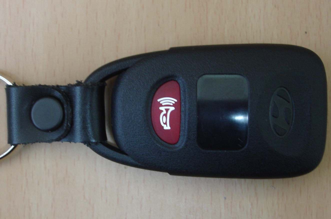
PINHA-T008
Mar 22, 2007Transmitter for RKE System
Equipment Class
DSC - Part 15 Security/Remote Control Transmitter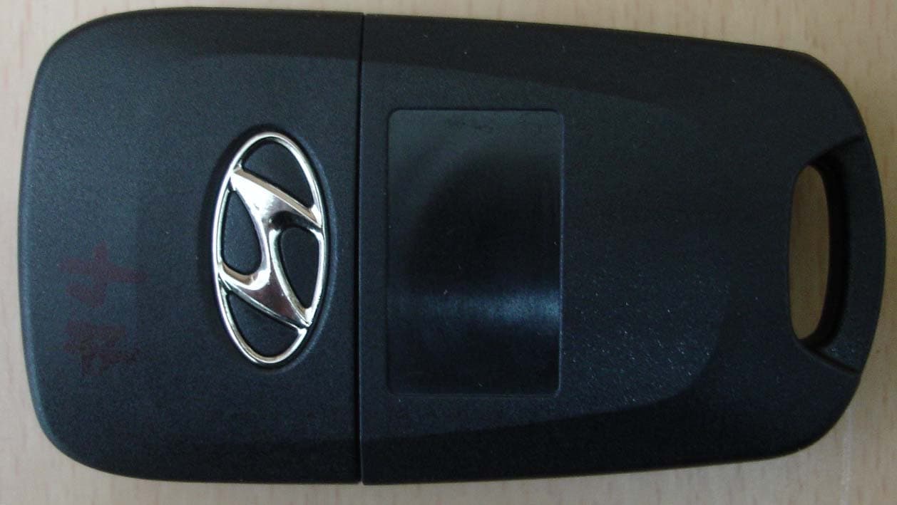
PINHA-T006
Mar 07, 2007Transmitter for RKE System
Equipment Class
DSC - Part 15 Security/Remote Control Transmitter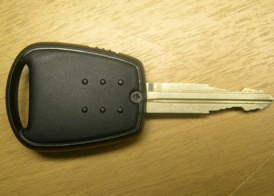
PINHA-T001
Dec 11, 2006Remote Keyless Entry System
Equipment Class
DSC - Part 15 Security/Remote Control Transmitter