PJUGH30502.4GHz Cordless Phone
Shenzhen Jingneng Telecom Technology Co Ltd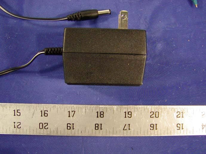
Click to zoom
Application Details
- Equipment Class
- DXT - Part 15 Low Power Transceiver, Rx Verified
- Date of Grant
- Jul 14, 2002
- Application Purpose
- Original Equipment
- Date of Application
- Jul 14, 2002
- Equipment Note
- 2.4GHz Cordless Phone
- Frequency Range
- 2474.00000000 - 2475.95000000
- Country
- China
Documents & Files
Document Text
Text extracted from the exhibit documents filed with the FCC. Open a document above to read the original.
Users Manual
2 CONTENTS IMPORTANTSAFETYINSTRUCTIONS................................................. 3 SAFETY INSTRUCTIONS FOR BATTERIES ........................................ 4 NAME OF CONTROLSAND INDICATIONS........................................... 5 FCC WANTS YOU TO KNOW............................................................... 8 INTRODUCTION FEATURES............................................................................................ 10 BOX CONTENTS .................................................................................. 11 INSTALLATION....................................................................................... 11 OPERATING INSTRUCTIONS CALLER ID SETUP ............................................................................... 16 TELEPHONE OPERATION................................................................... 21 MEMORY DIALING................................................................................. 28 CALLER ID OPERATION....................................................................... 35 ANSWERING SYSTERM OPERATION..................................................... 45 MESSAGE PLAYBACK.............................................................................. 49 TONE REMOTE OPERATION.................................................................. 52 TROUBLESHOOTING........................................................................... 59 PRODUCT CARE.................................................................................. 64 LIMITED WARRANTY............................................................................ 65 SERVICE............................................................................................... 67 WALLMOUNTTEMPLATE..................................................................... 68 3050manual 2-20.P652002-5-31, 9:242 3 WHEN USING YOUR TELEPHONE EQUIPMENT, BASIC SAFETY PRECAUTIONS SHOULDALWAYS BE FOLLOWED TO REDUCE THE RISK OF FIRE, ELECTRIC SHOCK AND INJURYTO PERSONS, INCLUDING THE FOLLOWING: 1. Do not use this product near water,for example,near a bath tub,wash bowl, kitchen sink,or laundry tub,in a wet basement,or near a swimming pool. 2. Avoid using a telephone (other than a cordless type)during an electrical storm. There may be a remote risk of electric shock from lightning. 3. Do not use the telephone to report a gas leak in the vicinity of the leak. 4. Use only the power cord and batteries indicated in this manual.Do not dispose of batteries in a fire.They may explode.Check with local codes for possible special disposal instructions. 5. CAUTION Danger of explosion if battery is incorrectly replaced. Replace only with the same or equivalent type recommended by the manufacturer. Dispose of used batteries according to the manufacturer's instructions. IMPORTANT SAFETY INSTRUCTIONS 3050manual 2-20.P652002-5-31, 9:243 4 SAFETY INSTRUCTIONS FOR BATTERIES CAUTION Use only a Southwestern Bell Freedom Phone approved battery pack in the handset of your GH3050 ordless Telephone. To reduce the risk of fire or personal injury, read and follow these instructions. 1. Use only a Southwestern Bell Freedom Phone approved Nickel Metal Hydride battery pack in the handset of your cordless telephone . For HANDSET UNIT: GP Ni-MH Battery GP60AAAH3BMX 3.6V, 600mAh or GREATPOWER Battery GP60AAAH3BMX3.6V,600mAH 2. Do not dispose of the battery in a fire, as it may explode. Check with local codes for possible special disposal instructions. 3. Do not open or mutilate the battery. Released electrolyte is corrosive and may cause damage to the eyes and skin. It may be toxic if swallowed. 4. Exercise care in handling batteries in order not to short the battery with conducting materials such as rings, bracelets and keys. The battery or conduction material may overheat and cause burns. 5. Charge the battery provided with or identified for use with this product only in accordance with the instructions and limitations specified in this manual. 6. Observe proper polarity orientation between the Battery Pack and battery charger. R R 3050manual 2-20.P652002-5-31, 9:244 5 NAME OF CONTROLS AND INDICATORS 3050manual 2-20.P652002-5-31, 9:245 6 LCD DISPLAY INDICATORS 1.NEW:indicates the number of new caller ID data items that have not been reviewed. 2.TOTAL:indicates the total number of stored Caller ID data items. 3.MEM:indicates the unit is in memory dial programming mode or memory dialing mode. 4.REP:indicates how many phone calls have been made from the same telephone number. 5.Arrow icon:indicates which arrow buttons can be used. 6.PROG:indicates the unit is in programming mode. 7.VIP:indicates that priority ringer has been set for the displayed number. LCD BACK LIGHT The LCD is back lit under the following conditions: 1. While receiving an incoming call (during ringing). 2. For 10 seconds, when the handset is picked up from the cradle. 3. For 10 seconds, when any button is pressed in the programming mode, Caller ID review mode or stored number review mode. 4. For 10 seconds, when any button is pressed in any mode other than those listed above. * The LCD back light goes off 10 seconds after the talk mode is terminated by pressing the TALK button, or immediately after the handset is placed in the base. ˇ ̨ˇ ̨ ̨ ˇ 3050manual 2-20.P652002-5-31, 9:246 7 NAME OF CONTROLS AND INDICATORS 3050manual 2-20.P652002-5-31, 9:247 8 FCC REQUIREMENT This equipment complies with Part 68 of the FCC rules and ACTA technical requirements.A label on the BASE UNIT of this equipment contains,among other information,the Registration Number and the Ringer Equivalence Number (REN) for this equipment. You must, upon request, provide this information to your telephone company. The REN is also useful in determining the quantity of devices that you may connect to your telephone line and still these devices to ring when your telephone number is called.In most areas,but not all, the sum of the /rens for all devices connected …
Text truncated - open the document above for the full version.
External Photos
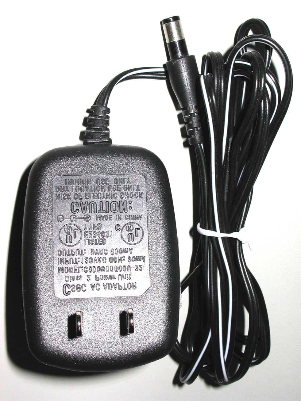
APPENDIX C - EUT EXTERNAL PHOTOGRAPHS Handset Chassis - Top View Handset Chassis - Bottom View Base Chassis - Top View Base Chassis - Bottom View Power Adapter - Top View
ID Label/Location Info
EXHIBIT A - FCC PRODUCT LABELING AND WARNING STATEMENT Proposed FCC ID Label Specifications: Text is black or white in color and is left justified. Labels are silk-screened and shall be “permanently affixed” at a conspicuous location on the EUT. Proposed Label Location on EUT Bottom Side of EUT Base/Proposed FCC ID Label Location/Handset FCC Warning Statement A FCC Warning Statement is provided in the product manual.
Internal Photos
APPENDIX C - EUT INTERNAL PHOTOGRAPHS Handset Main Board - Component View Handset Main Board - Solder View Handset Transceiver Component View Handset Transceiver - Solder View Base Main Board - Component View Base Main Board - Solder View Base Transceiver - Component View Base Transceiver - Solder View
Operational Description
ItemHandy. Tx(MHz) Handy. Rx(MHz)Base. Tx(MHz)Base. Rx(MHz) 1 2474.0002403.052403.05 2474.000 2 2474.0502403.12403.12474.050 3 2474.1002403.152403.15 2474.100 4 2474.1502403.22403.22474.150 5 2474.2002403.252403.25 2474.200 6 2474.2502403.32403.32474.250 7 2474.3002403.352403.35 2474.300 8 2474.3502403.42403.42474.350 9 2474.4002403.452403.45 2474.400 10 2474.4502403.52403.52474.450 11 2474.5002403.552403.55 2474.500 12 2474.5502403.62403.62474.550 13 2474.6002403.652403.65 2474.600 14 2474.6502403.72403.72474.650 15 2474.7002403.752403.75 2474.700 16 2474.7502403.82403.82474.750 17 2474.8002403.852403.85 2474.800 18 2474.8502403.92403.92474.850 19 2474.9002403.952403.95 2474.900 20 2474.950240424042474.950 21 2475.0002404.052404.05 2475.000 22 2475.0502404.12404.12475.050 23 2475.1002404.152404.15 2475.100 24 2475.1502404.22404.22475.150 25 2475.2002404.252404.25 2475.200 26 2475.2502404.32404.32475.250 27 2475.3002404.352404.35 2475.300 28 2475.3502404.42404.42475.350 29 2475.4002404.452404.45 2475.400 30 2475.4502404.52404.52475.450 31 2475.5002404.552404.55 2475.500 32 2475.5502404.62404.62475.550 33 2475.6002404.652404.65 2475.600 34 2475.6502404.72404.72475.650 35 2475.7002404.752404.75 2475.700 36 2475.7502404.82404.82475.750 37 2475.8002404.852404.85 2475.800 38 2475.8502404.92404.92475.850 39 2475.9002404.952404.95 2475.900 40 2475.950240524052475.950 3050 FREQUENCY TABLE
Test Report
Note: This test report is specially limited to the above client company and the product model only. It may not be duplicated without prior written consent of Bay Area Compliance Laboratory Corporation. This report must not be used by the client to claim product endorsement by NVLAP or any agency of the U.S. Government. FCC PART 15 SUBPART C EMI MEASUREMENT AND TEST REPORT For Shenzhen Jingneng Telecom Technology Co., Ltd. Baimenqian Industrial Zone, Shawan, Buji Town, Longgang District, Shenzhen City, P.R.China FCC ID: PJUGH3050 July 14, 2002 This Report Concerns: Original Report Equipment Type: 2.4GHz Cordless Telephone Test Engineer: Benjamin Jing Report No.: R0204266 Test Date: May 15, 2002 Reviewed By: Jeff Lee Prepared By: Bay Area Compliance Laboratory Corporation 230 Commercial Street Sunnyvale, CA 94085 Tel (408) 732-9162 Fax (408) 732-9164 Shenzhen Jingneng Telecom Technology Co., Ltd. FCC ID: PJUGH3050 Report # R0204266Rpt Page 2 of 14 FCC Part 15 Subpart C Test Report TABLE OF CONTENTS 1 - GENERAL INFORMATION..................................................................................................................................3 1.1 PRODUCT DESCRIPTION FOR EQUIPMENT UNDER TEST (EUT) ..............................................................................3 1.2 OBJECTIVE.............................................................................................................................................................3 1.3 RELATED SUBMITTAL(S)/GRANT(S) ......................................................................................................................3 1.4 TEST METHODOLOGY............................................................................................................................................3 1.5 TEST FACILITY.......................................................................................................................................................3 1.6 TEST EQUIPMENT LIST...........................................................................................................................................4 1.8 LOCAL SUPPORT EQUIPMENT LIST AND DETAILS...................................................................................................4 1.9 EXTERNAL I/O CABLING LIST AND DETAILS.........................................................................................................4 2 - SYSTEM TEST CONFIGURATION.....................................................................................................................5 2.1 DESCRIPTION OF TEST CONFIGURATION................................................................................................................5 2.2 CONFIGURATION OF TEST SYSTEM (BASE)............................................................................................................6 2.3 TEST SETUP BLOCK DIAGRAM...............................................................................................................................6 2.4 EQUIPMENT MODIFICATIONS.................................................................................................................................6 3 - CONDUCTED EMISSION .....................................................................................................................................7 3.1 MEASUREMENT UNCERTAINTY..............................................................................................................................7 3.2 EUT SETUP............................................................................................................................................................7 3.3 SPECTRUM ANALYZER SETUP................................................................................................................................7 3.4 TEST PROCEDURE..................................................................................................................................................7 3.5 SUMMARY OF TEST RESULTS.................................................................................................................................8 3.6 CONDUCTED EMISSIONS TEST DATA.....................................................................................................................8 3.7 PLOT OF CONDUCTED EMISSIONS TEST DATA.......................................................................................................8 4 - RADIATED EMISSION..........................................................................................................................................9 4.1 MEASUREMENT UNCERTAINTY..............................................................................................................................9 4.2 EUT SETUP............................................................................................................................................................9 4.3 SPECTRUM ANALYZER SETUP................................................................................................................................9 4.4 TEST PROCEDURE................................................................................................................................................10 4.5 CORRECTED AMPLITUDE & MARGIN CALCULATION...........................................................................................10 4.6 SUMMARY OF TEST RESULTS...............................................................................................................................10 4.7 RADIATED EMISSIONS TEST RESULT DATA.........................................................................................................11 5 - BAND EDGES ........................................................................................................................................................13 5.1 TEST PROCEDURE......................................................................................................................…
Text truncated - open the document above for the full version.
Test Setup Photos
EXHIBIT B - TEST SETUP PHOTOGRAPHS Base Conducted Emission - Front View Base Conducted Emission - Rear View Base Radiated Emission - Front View Base Radiated Emission - Rear View Handset Radiated Emission - Front View Handset Radiated Emission - Rear View
Contact Information
Applicant
Zheng Caian(QA Manager)
Test Firm
Bay Area Compliance LaboratoryJohn Chan
Technical Specifications
| # | Rule Parts | Frequency Range | Power Output |
|---|---|---|---|
| 2 | 15C | 2.47 GHz - 2.48 GHz | - |
Other Applications from Shenzhen Jingneng Telecom Technology Co Ltd
PJUGH9492
Jun 01, 20042.4G ANALOG CORDLESS PHONE WITH CID AND DAM
Equipment Class
DXX - Part 15 Low Power Communication Device Transmitter
PJU2400-01
Mar 18, 20032.4 GHz Cordless Telephone
Equipment Class
DXX - Part 15 Low Power Communication Device Transmitter
PJU2410-1
Feb 24, 2003Cordless Phone
Equipment Class
DXX - Part 15 Low Power Communication Device Transmitter
PJUHK250
Oct 24, 2002Cordless Telephone Base and Handset
Equipment Class
DXX - Part 15 Low Power Communication Device Transmitter
PJUTC970
May 20, 20022.4GHz Cordless Phone
Equipment Class
DXX - Part 15 Low Power Communication Device Transmitter