PKTUSBSTKARMLTE Band 12 USB Stick Modem
General Dynamics Broadband, Inc.
Click to zoom
Application Details
- Equipment Class
- TNB - Licensed Non-Broadcast Station Transmitter
- Date of Grant
- Dec 02, 2012
- Application Purpose
- Original Equipment
- Date of Application
- Nov 06, 2012
- Equipment Note
- LTE Band 12 USB Stick Modem
- Frequency Range
- 701.50000000 - 713.50000000
- Country
- United States
Documents & Files
Document Text
Text extracted from the exhibit documents filed with the FCC. Open a document above to read the original.
Users Manual
LTE USB Modem USER GUIDE 2 Contents Introduction ................................................................................... 4 1. Installing the IPWireless LTE Connection Manager .................. 7 2. IPWireless LTE Connection Manager ..................................... 12 3. LED Function ......................................................................... 17 4. Specifications ....................................................................... 18 5. Accessories ........................................................................... 20 6. Safety Precautions and Usage ............................................... 22 7. Additional Information ......................................................... 23 3 Introduction This User Guide provides installation and configuration instructions for the IPWireless LTE USB Modem. Follow the instructions in this guide to install the IPWireless LTE Connection Manager and driver files. This device is an LTE USB Modem operating with 3GPP LTE networks. Used with laptop or desktop computers, the device provides the user with superior performance for fixed or mobile Internet access. System Requirements For your IPWireless LTE USB Modem to work properly your computer must be running: • Operating System: ‐ Windows XP (32bit SP3, 64bit SP2) ‐ Windows Vista (32 or 64 bit) Operating System: ‐ Windows 7 (32 or 64 bit) • Minimum System Configuration: ‐ Intel Pentium III or faster ‐ 64MB RAM ‐ 200MB or greater free disk space ‐ USB 2.0 port 4 5 IPWireless LTE USB Modem Features The diagram below shows the main mechanical features of the IPWireless LTE USB Modem USIM Card USIM Card Orientation Slider to open RF Ports LED Indicator Installing USIM Card Before using the IPWireless LTE USB Modem, gently insert USIM card into the slot as shown on the previous page. Please pay attention to how to place the card in the slot. The metal contacts on the card should face downwards and the cut edge of the card will be visible after inserting the card into the slot ‐ the modem will not work if the card is inserted improperly. WARNING! The LTE USB stick currently supports the most popular mini card format. This is shown below by the red outline. The smaller micro SIM (shown by the white outline) can be supported also using the adaptor supplied with the USIM card. 6 1. Installing the IPWireless LTE Connection Manager The first time the IPWireless LTE USB Modem is connected to your computer it will automatically install the required drivers and application software. On subsequent connections this is not carried out. Connect the IPWireless LTE USB Modem to a USB port on your PC. If you don’t know where the USB port is, just look for the USB port symbol. If AutoPlay is enabled then the folder will automatically appear. 7 Double click on Install to start the installation process If autoplay is not enabled then you need to navigate to the drive manually in Windows explorer. Click on the Start button and then My Computer (Windows XP) or Computer (Windows Vista and Windows 7). Then double click on the drive named "IPWireless LTE USB Modem" and then double click on install 8 Depending on your operating system and/or system settings you may be prompted by User Account Control. Click Yes to continue the installation 9 Click Next to continue the installation Click Next to agree to the license agreement 10 Choose an alternative installation folder or click Install to use the default The setup program will take a few minutes to install The installation is now complete, click on Finish to exit. The IPWireless LTE Connection Manager will now start and the IPWireless LTE USB Modem drivers will be installed 11 2. IPWireless LTE Connection Manager The IPWireless LTE Connection Manager can be started by clicking the shortcut on the desktop. Detailed description of application functions is located in the help file that is available when you click the button: 12 Controls Connect / Disconnect Button Click the button to connect or disconnect the LTE Internet connection Main Window Display the main window. Status messages are displayed in the application area in the center of the main window. Tools Display the tools window. Help View the help files Minimize Minimize the IPWireless LTE Connection Manager to the Windows task bar. When minimized, the IPWireless LTE Connection Manager is still running and any internet connection is maintained. The IPWireless LTE Connection Manager can be displayed by double clicking the Windows task bar icon. 13 Close Close the IPWireless LTE Connection Manager. The IPWireless LTE Connection Manager is closed but the internet connection is maintained. The IPWireless LTE Connection Manager can be re‐opened to establish a new internet connection. 14 Uninstalling To uninstall the IPWireless LTE Connection Manager select: Start > IPWireless LTE USB Modem > Uninstall 15 13 Click Remove to uninstall the software. Click Finish to complete the uninstallation. 16 3. LED Function The IPWireless LTE USB Modem has a multi‐colour LED showing the current status of the modem as shown in the table below: LED Colour Status Red Initialising Amber flashingSearching for Network Coverage Green/Amber flashingNetwork is available, not connected Green Network is available, connected Green flashing Network is available, connected, data transfer in progress Red/Amber flashingNo Network available Red fast flashing then Green fast flashing Firmware upgrade in progress Red fast flashingNo USIM fitted Red/Green fast flashingSelf Test failure 17 4. Specifications The table below contains the technical specification for the equipment: Interface Type USB 2.0, USB Type A connector Supported Operating Systems Microsoft Windows XP, Vista, 7 Network Standards 3GPP LTE, Release 8 FDD and TDD modes User Equipment CategoryCategory 3 Maximum PHY Data Rate Up to 100Mbps downlink and 50 Mbps uplink in 20 MHz FDD Up to 100Mbps downlink and 30 Mbps uplink in 20 MHz TDD Actual data rates is ban…
Text truncated - open the document above for the full version.
Users Manual
Exposure to Radio Frequency Signals The following information includes important safety guidelines regarding exposure to radio frequency (RF) signals and the use of electronic devices. Your modem is a low power radio transmitter and receiver. When it is ON, it receives and also sends out RF signals. The USB Stick Modem has been evaluated against the Specific Absorption Rate (SAR) limits defined by the FCC for devices of this type. The highest reported SAR value complies with the 1.6W/kg averaged over 1g limit. This USB modem is approved for use in normal size laptop computers only (typically with 12 inch or larger display screens). To comply with FCC RF exposure requirements, this modem should not be used in configurations that cannot maintain a distance of at least 5mm (approximately 0.2 inch) from users and bystanders. In configurations where the 5mm cannot be maintained consult your service provider for advice. Examples where this may occur are certain small laptops and tablet computers or configurations where the USB connectors on the host computer are unable to provide or ensure the necessary separation between the modem and its users or bystanders to satisfy the RF exposure compliance requirements. If you use the modem in accordance with these guidelines, the level of RF exposure will fall within the guidelines and the standards previously identified. 1 The modem can be used with the remote antenna accessory, the remote antenna accessory has been evaluated against the Specific Absorption Rate (SAR) limit and complies with the 1.6W/kg averaged over 1g limit. Ensure a separation distance of at least 10mm is maintained between the remote antenna accessory and the user and bystanders. The maximum gain of the remote antenna must not exceed 1.7dBi (‐0.45dBd), operating the modem with an antenna gain exceeding this limit may void the user’s authority to operate the equipment. IPW‐2741 Iss.3 2
Users Manual
Remote Antenna for LTE Modem INSTRUCTIONS FOR USE 2 General Remarks In order to improve the data transfer performance, the LTE modem is designed to with the remote antenna. The antenna features a magnetic base that allows you to mount it on a metal surface e.g. a window sill. You can also screw the antenna on the wall either inside or outside. The antenna is equipped with a 3m cable terminated in suitable RF connectors for connecting the remote antenna to the modem. Specifications Frequency Range 690 –750MHz Gain max. 1.7dBi Polarisation Linear, +/‐45 o Power Input max. 4W Temperature Range‐20 o C to +55 o C Cable Length 3m Mounting the Antenna Before you connect the antenna to the modem you should assemble the antenna elements to the base unit. Gently tighten the antenna elements to the base unit. After attaching the antenna elements align them to so they angled at 45 degrees relative to the antenna base. 3 Installation on the Wall • Install screws spaced to match the locating lugs in the rear of the antenna, ensure the screw heads protrude approximately 1.5mm above the surface of the wall. • Located antenna on the on the screws as shown below. 4 Connecting to the Antenna Port of the Modem • Before connecting the remote antenna, move the slider on the bottom of the modem to reveal the antenna connectors. Ensure the sliders is fully open. • Connect the remote antenna connectors to the modem as shown below. • Both cables from the remote antenna must be connected to the modem. Antenna Slider
External Photos
Figure 1: Top View Figure 2: Bottom View
External Photos
Figure 1: Remote Antenna Assembly Figure 2: Remote Antenna Disassembled Figure 3: Label Figure 4: USB Stick Connectors Figure 5: Reverse SMA Antenna Connector
Internal Photos
Figure 1: Top Cover Removed Figure 2: Bottom Cover Removed Figure 3: Top of Main Board with Shield and Antenna Figure 4: Bottom with Daughter card Fitted Figure 5: Bottom with Daughter Card Removed Figure 6: Top of Daughter Card (SD Card Fitted) Figure 7: Bottom of Daughter Card Figure 8: Main Board Top ‐ Shield Removed Figure 9: Main Board Bottom – Shield Removed
Operational Description
General Dynamics Broadband Proprietary and Confidential Single Band 700MHz Antenna Product Data Sheet Description Specification Product type Single Band MIMO antenna Frequency Range 690 – 750MHz Diversity Space and polarisation Gain (peak / XY plane average) 1.7dBi for 700MHz Pattern Omni‐directional Polarisation linear, +/‐45° Power input 4W maximum Impedance 50 Ohms VSWR < 2.5:1 Connector type Dual AC‐162 Cable type ARC‐100D dual RF cable, 3.0mm dia. Cable length 3m Cable loss 2.0dB@700MHz Dimensions (L x W x H) 165 x 62 x 18 mm (stand only) 165 x 62 x 200 mm (incl. antennas) Weight 800g Operating temperature ‐20° to +55°C Environmental IP65 Approvals RoHS Sales Pack Box, User Guide Installation Options Indoor desktop stand Indoor and outdoor wall mount Outdoor window sill Antenna base Mounting plate with magnet Holes for screw mounts
RF Exposure Info
TEST REPORT Test of: General Dynamics Broadband, LTE USB Stick: ARM & Antenna: LTE-ODUP003-IPW To: OET Bulletin 65 Supplement C: (2001-01) IEEE 1528: 2003 FCC ID: PKTUSBSTKARM Test Report Serial No: UL-SAR-RP88727J02A V6.0 Version 6.0 Supersedes All Previous Versions This Test Report Is Issued Under The Authority Of Richelieu Quoi, SAR Technology Consultant: (APPROVED SIGNATORY) Checked By: Naseer Mirza (APPROVED SIGNATORY) Issue Date: 30 November 2012 Test Dates: 20 August 2012 to 31 October 2012 This report is issued in portable document format (PDF). It is only a valid copy of the report if it is being viewed in PDF format with the following security options not allowed: Changing the document, Selecting text and graphics, Adding or changing notes and form fields. This report may not be reproduced other than in full, except with the prior written approval of UL. The results in this report apply only to the sample(s) tested. Test Report Serial No: UL-SAR-RP88727J02A V6.0 Version 6.0 Issue Date: 30 November 2012 Page: 2 of 149 RFI Global Services Ltd. This page has been left intentionally blank. Test Report Serial No: UL-SAR-RP88727J02A V6.0 Version 6.0 Issue Date: 30 November 2012 Page: 3 of 149 RFI Global Services Ltd. TABLE OF CONTENTS 1. Customer Information ..................................................................................................... 4 2. Equipment Under Test (EUT).......................................................................................... 5 3. Test Specification, Methods and Procedures ............................................................. 10 4. Deviations from the Test Specification ....................................................................... 11 5. Operation and Configuration of the EUT during Testing ........................................... 12 6. Summary of Test Results ............................................................................................. 16 7. Measurements, Examinations and Derived Results ................................................... 18 8. Measurement Uncertainty ............................................................................................ 27 Appendix 1. Test Equipment Used .................................................................................. 29 Appendix 2. Measurement Methods ................................................................................ 32 Appendix 3. SAR Distribution Scans for USB Dongle .................................................... 34 Appendix 4. SAR Distribution Scans for USB Dongle + Antenna Attached .................. 66 Appendix 5. SAR Distribution Scans for System Performance Check ........................ 110 Appendix 6. Photographs ............................................................................................... 118 Appendix 7. System Check ............................................................................................ 144 Appendix 8. Simulated Tissues...................................................................................... 146 Appendix 9. DASY4 System Details ............................................................................... 147 Test Report Serial No: UL-SAR-RP88727J02A V6.0 Version 6.0 Issue Date: 30 November 2012 Page: 4 of 149 RFI Global Services Ltd. 1. Customer Information Company Name: General Dynamics Broadband Address: Unit 7 Greenways Business Park Bellinger Close Chippenham Wilts SN15 1BN United Kingdom Test Report Serial No: UL-SAR-RP88727J02A V6.0 Version 6.0 Issue Date: 30 November 2012 Page: 5 of 149 RFI Global Services Ltd. 2. Equipment Under Test (EUT) 2.1. Identification of Equipment Under Test (EUT) Description: LTE USB Stick Brand Name: General Dynamics Broadband. Model Name or Number: ARM Serial Number: ARMHC0001F12 IMEI Number: Not Applicable Hardware Version Number: Pass 1 Software Version Number: Rel.3 Hardware Revision of GSM Module: Not Applicable Software Revision of GSM Module: Not Applicable FCC ID Number: PKTUSBSTKARM Country of Manufacture: None Stated Date of Receipt: 20 August 2012 2.2. Identification of Equipment Under Test (EUT) Description: LTE USB Stick Antenna Brand Name: General Dynamics Broadband. Model Name or Number: LTE-ODUP003-IPW Serial Number: GT1229LT006040 IMEI Number: Not Applicable Cable Length and Type: ~3.2 m Dual RF Cable Hardware Version Number: None Stated Country of Manufacture: China Date of Receipt: 20 August 2012 2.3. Description of EUT The Equipment Under Test is a LTE USB Dongle Stick Modem and an attachable antenna with Mono band capability supporting LTE Band 12, 5 MHz Bandwidth channel. The EUT is a power class 3 device. Test Report Serial No: UL-SAR-RP88727J02A V6.0 Version 6.0 Issue Date: 30 November 2012 Page: 6 of 149 RFI Global Services Ltd. 2.4. Accessories The following accessories were supplied with the EUT during testing: Description: USB Cable Brand Name: None Stated Model Name or Number: None Stated Serial Number: Not Applicable Cable Length and Type: ~132.5mm USB Cable Country of Manufacture: None Sated Connected to Port Standard USB Port 2.5. Support Equipment The following support equipment was used to exercise the EUT during testing: Description: Laptop PC Brand Name: Dell Model Name or Number: Latitude D620 Serial Number: None Stated Cable Length and Type: Not Applicable Connected to Port: Not Applicable Description: Radio Communication Analyzer Brand Name: Anritsu Model Name or Number: MT8820C Serial Number: 6200938937 Cable Length and Type: ~4.0m Utiflex Cable Connected to Port: RF (Input / Output) Air Link Test Report Serial No: UL-SAR-RP88727J02A V6.0 Version 6.0 Issue Date: 30 November 2012 Page: 7 of 149 RFI Global Services Ltd. 2.6. Additional Information Related to Testing Equipment Category LTE Band 12 Type of Unit Fixed Transceiver supported via Portable device Intended Operating Environment: Within LTE coverage/ General Population/Uncontrolled limits Transmitter Maximum Output Power Cha…
Text truncated - open the document above for the full version.
Test Report
TEST REPORT FROM RFI GLOBAL SERVICES LTD Test of: ARM LTE Band 12, 5 MHz Channel Bandwidth FCC ID: PKTUSBSTKARM To: FCC Parts 2.1046, 2.1049, 2.1051, 2.1053, 2.1055, 15.107, 15.109, 15.111, 27.50(c)(9), 27.53(g) & 27.54 Test Report Serial No.: RFI-RPT-RP88727JD01A This Test Report Is Issued Under The Authority Of John Newell, Group Quality Manager: Checked By: Sarah Williams Signature: Date of Issue: 07 September 2012 This report is issued in Adobe Acrobat portable document format (PDF). It is only a valid copy of the report if it is being viewed in PDF format with the following security options not allowed: Changing the document, Selecting text and graphics, Adding or changing notes and form fields. This report may not be reproduced other than in full, except with the prior written approval of RFI Global Services Ltd. The results in this report apply only to the sample(s) tested. TEST REPORT SERIAL NO: RFI-RPT-RP88727JD01A VERSION NO. 1.0 ISSUE DATE: 07 SEPTEMBER 2012 Page 2 of 76 RFI Global Services Ltd This page has been left intentionally blank. TEST REPORT SERIAL NO: RFI-RPT-RP88727JD01A VERSION NO. 1.0 ISSUE DATE: 07 SEPTEMBER 2012 RFI Global Services Ltd Page 3 of 76 Table of Contents 1. Customer Information .................................................................................................................. 4 2. Summary of Testing ..................................................................................................................... 5 2.1. General Information 5 2.2. Summary of Test Results 5 2.3. Methods and Procedures 6 2.4. Deviations from the Test Specification 6 3. Equipment Under Test (EUT) ....................................................................................................... 7 3.1. Identification of Equipment Under Test (EUT) 7 3.2. Description of EUT 7 3.3. Modifications Incorporated in the EUT 7 3.4. Additional Information Related to Testing 8 3.5. Support Equipment 8 4. Operation and Monitoring of the EUT during Testing ............................................................... 9 4.1. Operating Modes 9 4.2. Configuration and Peripherals 9 5. Measurements, Examinations and Derived Results ................................................................ 10 5.1. General Comments 10 5.2. Test Results 11 5.2.1. Receiver/Idle Mode AC Conducted Emissions 11 5.2.2. Receiver/Idle Mode Radiated Spurious Emissions 15 5.2.3. Receiver/Idle Mode Radiated Spurious Emissions – External Antenna’s 19 5.2.4. Receiver/Idle Mode Conducted Spurious Emissions – Main RF Port 23 5.2.5. Receiver/Idle Mode Conducted Spurious Emissions – Diversity RF Port 25 5.2.6. Transmitter Carrier Output Power and Effective Radiated Power (ERP) 27 5.2.7. Transmitter Occupied Bandwidth 35 5.2.8. Transmitter Conducted Spurious Emissions 43 5.2.9. Transmitter Conducted Emissions at Band Edges 46 5.2.10. Transmitter Radiated Spurious Emissions 52 5.2.11. Transmitter Radiated Emissions at Band Edges 55 5.2.12. Transmitter Radiated Spurious Emissions – External Antenna’s 61 5.2.13. Transmitter Radiated Emissions at Band Edges - External Antenna’s 64 5.2.14. Transmitter Frequency Stability (Temperature Variation) 70 5.2.15. Transmitter Frequency Stability (Voltage Variation) 74 6. Measurement Uncertainty .......................................................................................................... 75 7. Report Revision History ............................................................................................................. 76 TEST REPORT SERIAL NO: RFI-RPT-RP88727JD01A VERSION NO. 1.0 ISSUE DATE: 07 SEPTEMBER 2012 Page 4 of 76 RFI Global Services Ltd 1. Customer Information Company Name: General Dynamics Broadband Address: Unit 7 Greenways Business Park Bellinger Close Chippenham Wilts SN15 1BN United Kingdom TEST REPORT SERIAL NO: RFI-RPT-RP88727JD01A VERSION NO. 1.0 ISSUE DATE: 07 SEPTEMBER 2012 RFI Global Services Ltd Page 5 of 76 2. Summary of Testing 2.1. General Information Specification Reference: 47CFR27 Specification Title: Code of Federal Regulations Volume 47 (Telecommunications) 2011: Part 27 Subpart C (Miscellaneous Wireless Communication Services) Specification Reference: 47CFR15.107, 47CFR15.109 and CFR15.111 Specification Title: Code of Federal Regulations Volume 47 (Telecommunications) 2011: Part 15 Subpart B (Unintentional Radiators) - Sections 15.107, 15.109 and 15.111 Site Registration: 209735 Location of Testing: RFI Global Services Ltd, Wade Road, Basingstoke, Hampshire, RG24 8AH. Test Dates: 16 August 2012 to 23 August 2012 2.2. Summary of Test Results FCC Reference (47CFR) Measurement Result 15.107 Receiver/Idle Mode AC Conducted Emissions 15.109 Receiver/Idle Mode Radiated Spurious Emissions 15.109 Receiver/Idle Mode Radiated Spurious Emissions – External Antenna 15.111 / 2.1051 Receiver/Idle Mode Conducted Spurious Emissions – Main RF Port 15.111 / 2.1051 Receiver/Idle Mode Conducted Spurious Emissions – Diversity RF Port 27.50(c)(10) / 2.1046 Transmitter Carrier Output Power and Effective Radiated Power (ERP) 2.1049 Transmitter Occupied Bandwidth 27.53(g) / 2.1051 Transmitter Conducted Spurious Emissions 27.53(g) / 2.1051 Transmitter Conducted Emissions at Band Edges 27.53(g) / 2.1053 Transmitter Radiated Spurious Emissions 27.53(g) / 2.1053 Transmitter Radiated Emissions at Band Edges 27.53(g) / 2.1053 Transmitter Radiated Spurious Emissions – External Antenna 27.53(g) / 2.1053 Transmitter Radiated Emissions at Band Edges – External Antenna 27.54 / 2.1055 Transmitter Frequency Stability Key to Results = Complied = Did not comply TEST REPORT SERIAL NO: RFI-RPT-RP88727JD01A VERSION NO. 1.0 ISSUE DATE: 07 SEPTEMBER 2012 Page 6 of 76 RFI Global Services Ltd 2.3. Methods and Procedures Reference: ANSI/TIA-603-C-2004 Title: Land Mobile Communications Equipment, Measurements and performance Standards Reference: ANSI C63.4 (2009) Title: American National Standard for Methods of Measurement of Radio-Noise Emissions from Low-Vol…
Text truncated - open the document above for the full version.
Contact Information
Applicant
Joseph Cheung
Technical Contact
General Dynamics Broadband Inc.Peter Warburg
[email protected]+4412490800100
7 Greenways Business Park, Bellinger Close · Chippenham · United Kingdom
Test Firm
UL VS LtdDarren Rust
Technical Specifications
| # | Rule Parts | Frequency Range | Power Output | Emission | Tolerance |
|---|---|---|---|---|---|
| 2 | 27 | 701.5 MHz - 713.5 MHz | 211.00 mW | 4M51D7W | 0.1 ppm |
Other Applications from General Dynamics Broadband, Inc.
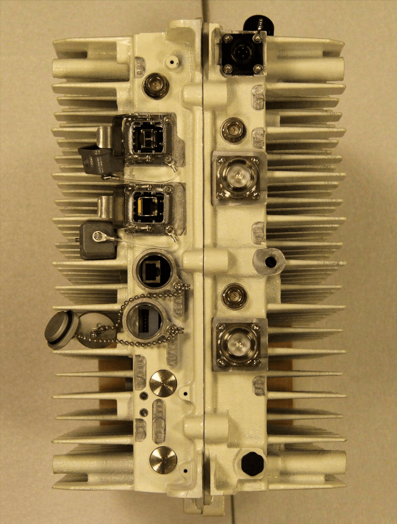
PKTNODEBAZY
Oct 21, 2015Band 12 LTE Base Station
Equipment Class
TNB - Licensed Non-Broadcast Station Transmitter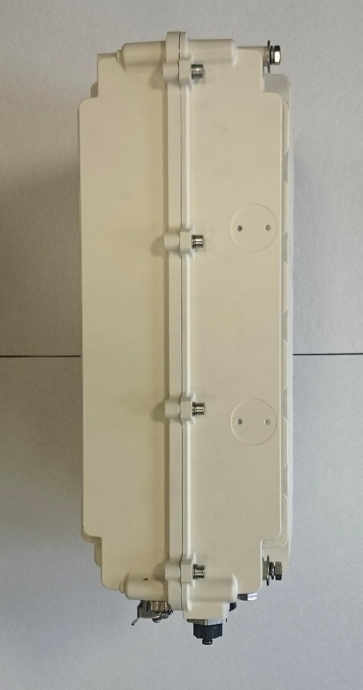
PKTNODEBBBK
Mar 23, 2015Band 14 LTE Base Station
Equipment Class
TNB - Licensed Non-Broadcast Station Transmitter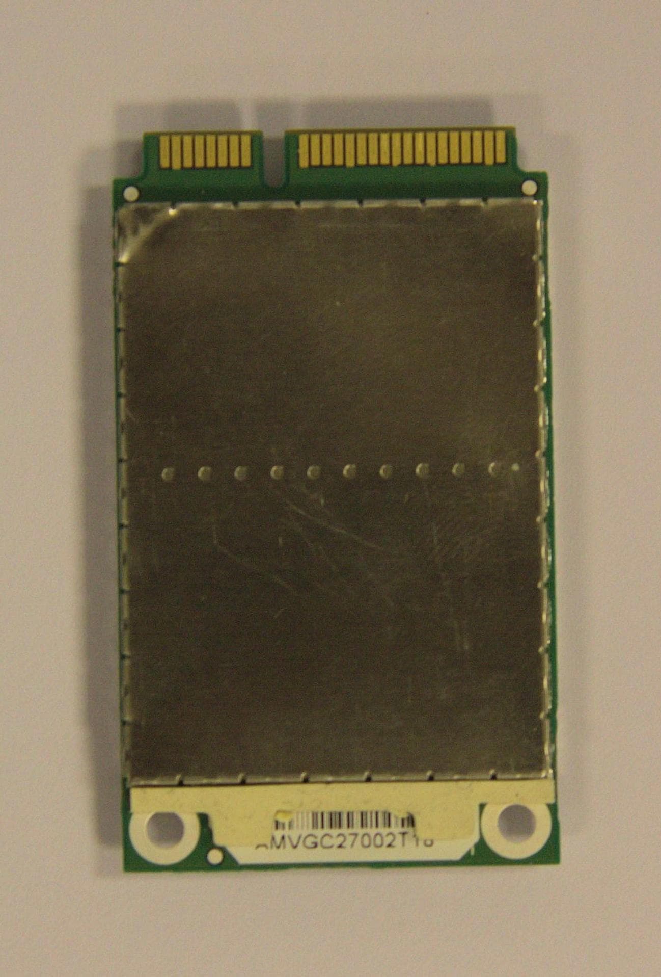
PKTPEMAMW1
Apr 03, 2014Broadband PCI Express Mini Module
Equipment Class
TNB - Licensed Non-Broadcast Station Transmitter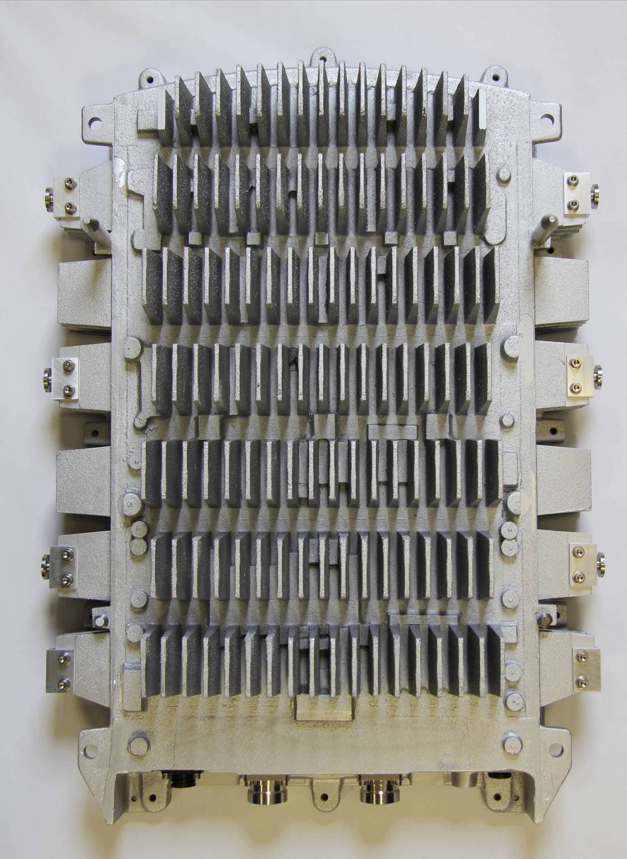
PKTNODEBAQQ
Oct 03, 20123GPP Band 12 LTE Base Station
Equipment Class
TNB - Licensed Non-Broadcast Station Transmitter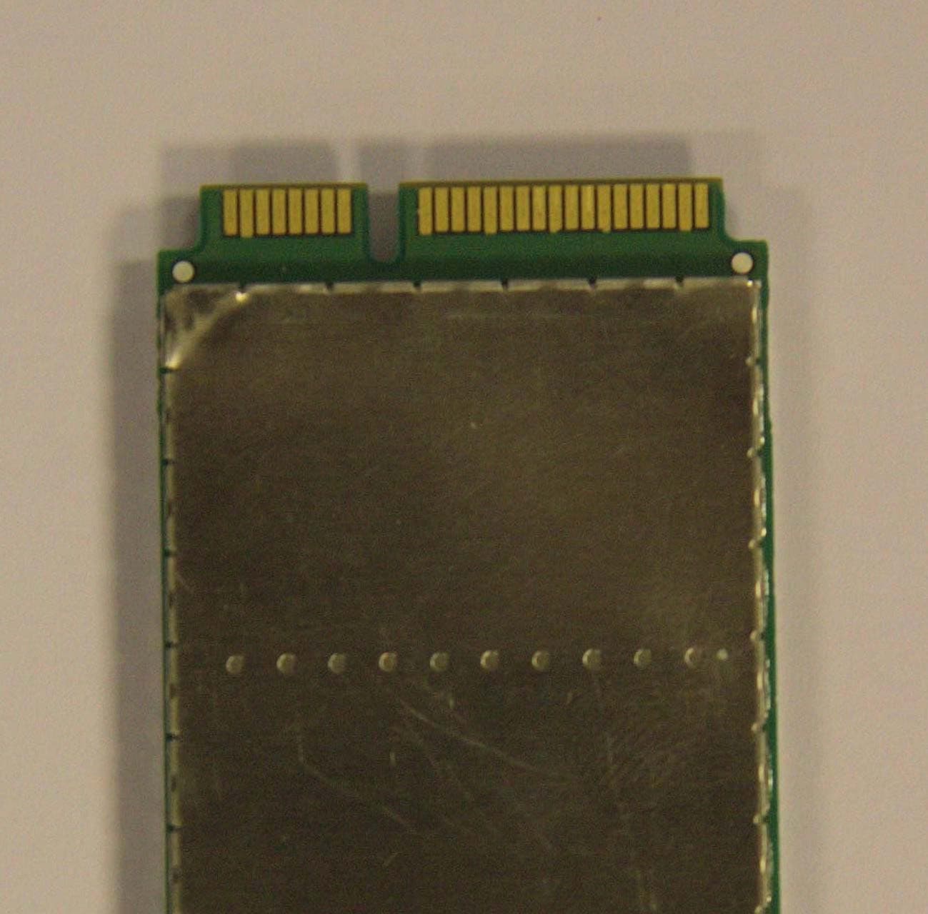
PKTPEMAMW
Sep 12, 2012LTE Band 4 and 12 Modem
Equipment Class
TNB - Licensed Non-Broadcast Station Transmitter