PM3FRS300Family Radio Service 500 mW transceiver
Genex Telecom Co., Ltd.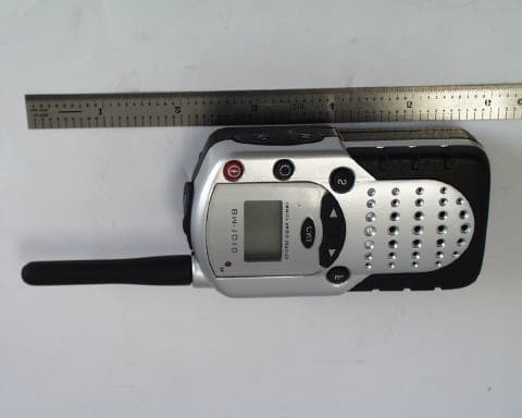
Click to zoom
Application Details
- Equipment Class
- FRF - Part 95 Family Radio Face Held Transmitter
- Date of Grant
- Aug 20, 2001
- Application Purpose
- Original Equipment
- Date of Application
- May 08, 2001
- Equipment Note
- Family Radio Service 500 mW transceiver
- Frequency Range
- 462.56250000 - 467.71250000
- Company
- Genex Telecom Co., Ltd.
- Country
- South Korea
Documents & Files
Document Text
Text extracted from the exhibit documents filed with the FCC. Open a document above to read the original.
Users Manual
ROGERS LABS, INC.Genex Electronics 4405 W. 259th TerraceMODEL: FRS 300 Louisburg, KS 66053Test #: 010419 Phone/Fax: (913) 837-3214Test to: FCC Parts 2 and 95Page 1 of 2 FRS300Manual.doc 05/09/2001 FRS 300 Owners Operator Manual Turning the Unit ON Press and hold the power button. The unit will beep and the LCD display will briefly display a self-test screen. Turning the Unit OFF Press and hold the power button. The unit will beep and the LCD display will turn blank. Adjusting the Speaker Volume • Press the UP (<) button to increase volume. • Press the DOWN (>) button to decrease volume. • The LCD displays volume level on lower right corner by the number of bars. Receiving a Signal The unit is continuously in the RECEIVE mode when the unit is ON. When you receive a Signal on the current channel, the TX/RX LED lights up in green Transmitting a Signal 1. Push and hold the PTT button to transmit. The TX will light up in red. 2. While holding the PTT button, speak in a normal voice about 2 to 3 inches away from the microphone. 3. Release the PTT button when you have finished transmitting. NOTE: In order for other people to receive your transmission, they must be on the same channel you are currently using. Refer to the “Changing Channels” section for more information. Changing Channels This communicator has 14 available channels. To change channels: 1. Press and hold the MENU button until the channel number digit flashes on the LCD display. 2. While the channel number is flashing: • Press the UP (<) button for a higher channel. • Press the DOWN (>) button for a lower channel. • The channel changes from 1 to 14, or from 14 to 1, repeatedly. 3. Press the MENU button or PTT button to select the desired channel and return to normal mode. Monitor You can use the MONITOR feature to check for weak signals in the current channel. • Press and hold the MONITOR button until it beeps. MONITOR works continuously until released – pressed MONITOR again. • Press the MONITOR button for channel skipping during SCAN mode. LAMP+ (LAMP / KEY LOCK) • Press and release the LAMP+ key to light up the LCD display. The backlight will automatically shut off after 4 seconds when no key operation is made. • Press and hold the LAMP+ key until the KEY LOCK symbol is displayed. Volume and channel change is disabled during KEY LOCK mode. Press the LAMP+ key the same manner again to release KEY LOCK mode. CHANNEL SCAN The SCAN activity works in an endless channel loop from 1 to 14. 1. Press the MENU button until Channel number digit flashes. Press the SCAN button to activate channel scan. The channel number on LCD changes rapidly until an active signal is detected. 2. When an active signal (one of the 14 channels) is detected, SCAN pauses keeping the active signal broadcast. Press PTT if you wish to communicate through the active signal channel. Then SCAN is stopped at the active channel. But if communication is not desired, press UP/DOWN button to continue searching. ROGERS LABS, INC.Genex Electronics 4405 W. 259th TerraceMODEL: FRS 300 Louisburg, KS 66053Test #: 010419 Phone/Fax: (913) 837-3214Test to: FCC Parts 2 and 95Page 2 of 2 FRS300Manual.doc 05/09/2001 3. Press the SCAN button to deactivate channel scan. The SCAN stops at starting channel when no detection is made. But the SCAN stops at a different channel when detection is made. Battery Level / Low Battery Indication • The LCD screen displays the battery level according to the number of squares lit inside the battery symbol. • When the battery level is low, the battery icon will flash to indicate that the batteries need to be replaced. Sending Call Tones You can use Call Tones to alert the other user or to identify yourself. You can also use Call Tones to signal the beginning or the end of a transmission. 1. Press and release the CALL button. 2. Your Call Tones will transmit. Accessory Connection The model is designed to work with various accessories. When those accessories are connected through the ACCESSORY CONNECTOR, the headphone symbol will display on LCD indicating this model operating with accessories. FCC Information THIS DEVICE COMPLIES WITH PART 15 OF THE FCC RULES. OPERATION IS SUBJECT TO THE FOLLOWING TWO CONDITIONS : (1) THIS DEVICE MAU NOT CAUSE HARMFUL INTERFERENCE, AND (2) THIS DEVICE MUST ACCEPT ANY INTERFERENCE RECEIVED, INCLUDING INTERFERENCE THAT MAY CAUSE UNDERSIRED OPERATION. Safety Information For FRS UNIT Your wireless handheld portable transceiver contains a low power transmitter. When the PTT button is pushed it sends out radio frequency (RF) signals. This device is authorized to operate at a duty factor not to exceed 50%. In August 1996, the Federal Communications Commission (FCC) adopted RF exposure guidelines with safety levels for hand-held wireless devices. Important: To maintain compliance with the FCC’s RF exposure guidelines, hold the transmitter at least 1 inch (2.5 centimeters) from your face and speak in a normal voice, with the antenna pointed up and away. If you wear the handset on your body while using the headset accessory, DO NOT TRANSMIT. The BM-1010 supplied belt clip is for storage purposes ONLY. Use only the supplied antenna. Unauthorized antennas, modifications, or attachments could damage the transmitter and may violate FCC regulations. Normal Position: Hold the transmitter approximately 1” from your face and speak in a normal voice, with the antenna pointed up and away.
Cover Letter(s)
May 10, 2001 Federal Communications Commission Equipment Approval Services P.O. Box 35815 Pittsburgh, PA 15251-3315 Applicant:Genex Electronics Co. LTD 3263 HA-AHN Industrial Zone 201 HA-AHN 3-Dong Kwang Myung-City 423-754 Korea Equipment:FCC ID: PM3 FRS-300 FCC Rules:Part 2 and 95 Gentlemen: The Application Form 159 with filing fees attached, for Certification of Intentional Radiators operated in the Family Radio Service (FRS) frequency range of 462 and 467 MHz, has been completed and funds electronically transferred for the above mentioned application. The 731 form and application have been electronically submitted and any attachments will be up loaded to the FCC web site. Should you require any further information, please contact the undersigned. Thank you for your consideration in this matter. Sincerely, Scot Rogers Rogers Labs, Inc. Enclosures ROGERS LABS, INC. 4405 West 259 th Terrace Louisburg, KS 66053 Phone / Fax (913) 837-3214
Cover Letter(s)
May 10, 2001 Federal Communications Commission Equipment Approval Services P.O. Box 35815 Pittsburgh, PA 15251-3315 Applicant:Genex Electronics Co. LTD 3263 HA-AHN Industrial Zone 201 HA-AHN 3-Dong Kwang Myung-City 423-754 Korea Equipment:FCC ID: PM3 FRS-300 FCC Rules:Part 2 and 95 Gentlemen: The Application Form 159 with filing fees attached, for Certification of Intentional Radiators operated in the Family Radio Service (FRS) frequency range of 462 and 467 MHz, has been completed and funds electronically transferred for the above mentioned application. The 731 form and application have been electronically submitted and any attachments will be up loaded to the FCC web site. Should you require any further information, please contact the undersigned. Thank you for your consideration in this matter. Sincerely, Scot Rogers Rogers Labs, Inc. Enclosures ROGERS LABS, INC. 4405 West 259 th Terrace Louisburg, KS 66053 Phone / Fax (913) 837-3214
Cover Letter(s)
June 5, 2001 Federal Communications Commission Equipment Approval Services P.O. Box 35815 Pittsburgh, PA 15251-3315 Applicant:Genex Electronics Co. LTD 3263 HA-AHN Industrial Zone 201 HA-AHN 3-Dong Kwang Myung-City 423-754 Korea Equipment:FCC ID: PM3 FRS-300 FCC Rules:Part 2 and 95 RE:Request for FCC ID change Gentlemen: This letter is a request for a FCC identification number change for a pending application submittal. Genex Electronics Co. LTD. requests that the FCC identification number be changed from PM3 FRS- 300 to PM3 FRS300. The Application Form 159 with filing fees attached, for Certification of Intentional Radiators operated in the Family Radio Service (FRS) frequency range of 462 and 467 MHz, has been completed and funds electronically transferred for the above mentioned application. A new FCC ID label has been submitted and uploaded to the FCC web page. Should you require any further information, please contact the undersigned. Thank you for your consideration in this matter. Sincerely, Scot Rogers Rogers Labs, Inc. Enclosures ROGERS LABS, INC. 4405 West 259 th Terrace Louisburg, KS 66053 Phone / Fax (913) 837-3214
Cover Letter(s)
ROGERS LABS, INC.INTERMEC TECHNOLOGIES CORPORATION 4405 W. 259th TerraceMODEL: 1555 Hand Held Reader Louisburg, KS 66053Test #: 000815FCCID#: HN21555-900 Phone/Fax: (913) 837-3214Test to: FCC Parts 2 and 15FCCresponseletterref16801.doc 08/17/2001 August 17, 2001 Federal Communications Commission Equipment Approval Services P.O. Box 35815 Pittsburgh, PA 15251-3315 Applicant:Genex Electronics Co. LTD 3263 HA-AHN Industrial Zone 201 HA-AHN 3-Dong Kwang Myung-City 423-754 Korea RE: Correspondence Reference Number: 20262 Equipment:FCC ID: PM3 FRS 300 Gentlemen: Please find enclosed the response to request for additional information regarding the submittal for grant of certification of this FRS unit. A copy of the information request has been reproduced here for reference. To:Scot Rogers, Rogers Labs, Inc From:Diane Poole [email protected] FCC Application Processing Branch Re:FCC ID PM3FRS300 Applicant:Genex Electronics Co. LTD Correspondence Reference Number:20262 731 Confirmation Number:EA100934 1. The ERP power for this device is .4 Watts (not .5 Watts as on technical spec). 2. Please retest the occupied bandwidth with span 5kHz/div. 3. Submit Radiated spurious Emission data using substitution method. ROGERS LABS, INC. 4405 West 259 th Terrace Louisburg, KS 66053 Phone / Fax (913) 837-3214 l Page 2August 17, 2001 ROGERS LABS, INC.Genex Electronics Co. LTD 4405 West 259 th TerraceMODEL: PRO-300 Family Radio Service (FRS) Transceiver Louisburg, KS 66053Test #:010801FCC ID#: PM3 FRS-300 Phone/Fax: (913) 837-3214CERTIFICATION\FRS300FCCresponseletter19906.doc 04/19/01 RESPONSE The EPR Power was measured using the following technique. 1. The EUT was placed on a turntable, located on the OATS, at a distance of three meters from the receiving antenna. The unit was powered on and transmitted a signal. This radiated signal strength was maximized and the amplitude level, as read from the spectrum analyzer, was recorded as 104.7 dBμV. The unit was removed from the turntable and replaced with a ½ wave dipole antenna (tuned to 460 MHz). A signal generator with amplifier and coaxial cable was used to energize the antenna. The amplitude was increased at the signal generator until the measured field strength read the same amplitude as that recorded for the EUT (104.7 dBμV). The energy required to produce the measured field strength was then recorded as 27.0 dBm. 2. The occupied bandwidth has been retaken with an audio input signal of 2500 Hz and is shown below. This measurement was made using indirect coupling of the output. There is no correlation of power shown on this plot. l Page 3August 17, 2001 ROGERS LABS, INC.Genex Electronics Co. LTD 4405 West 259 th TerraceMODEL: PRO-300 Family Radio Service (FRS) Transceiver Louisburg, KS 66053Test #:010801FCC ID#: PM3 FRS-300 Phone/Fax: (913) 837-3214CERTIFICATION\FRS300FCCresponseletter19906.doc 04/19/01 3. The radiated spurious emissions data has been taken using the substitution method. Please note TIA/EIA-603 directs the radiated spurious emissions are emissions from the equipment when transmitting into a non-radiating load. The antenna system of the EUT is attached and cannot be replaced with a non-radiating load. Therefore, the spurious emissions data was taken with the EUT transmitting into the attached antenna. A ½ wave dipole antenna was used for the substitution antenna in the following data. Channel 467.7125 MHz Frequency (MHz) FSM EUT Horz. (dBμV) Sub. Gen. Level (dBμV) FSM Vert. (dBμV) Sub. Gen. Level (dBμV) Horizontal (dBc) Vertical (dBc) 467.789.8119.0104.7134.0-- 935.435.165.741.080.853.353.2 A log periodic antenna was used for the substitution antenna for the following data. Frequency (MHz) FSM EUT Horz. (dBμV) Sub. Gen. Level (dBμV) FSM Vert. (dBμV) Sub. Gen. Level (dBμV) Horizontal (dBc) Vertical (dBc) 1403.140.567.843.670.151.263.9 1870.939.369.040.370.550.063.5 We would greatly appreciate your prompt attention in this submittal. Should you require any further information, please contact the undersigned. Thank you for your consideration in this matter. Sincerely, Scot Rogers Rogers Labs, Inc. Enclosures
External Photos
ROGERS LABS, INC.Genex Electronics 4405 W. 259th TerraceMODEL: FRS 300 Louisburg, KS 66053Test #: 010419 Phone/Fax: (913) 837-3214Test to: FCC Parts 2 and 95Page 1 of 2 FRS300EXTPHO.doc 05/09/2001 External Photographs of FRS 300 ROGERS LABS, INC.Genex Electronics 4405 W. 259th TerraceMODEL: FRS 300 Louisburg, KS 66053Test #: 010419 Phone/Fax: (913) 837-3214Test to: FCC Parts 2 and 95Page 2 of 2 FRS300EXTPHO.doc 05/09/2001
ID Label/Location Info
ROGERS LABS, INC.Genex Electronics 4405 W. 259th TerraceMODEL: FRS 300 Louisburg, KS 66053Test #: 010419 Phone/Fax: (913) 837-3214Test to: FCC Parts 2 and 95Page 1 of 1 FRS300Label.doc 05/10/2001 FCC ID Label placement and Label for FRS 300
ID Label/Location Info
ROGERS LABS, INC.Genex Electronics 4405 W. 259th TerraceMODEL: FRS 300 Louisburg, KS 66053Test #: 010419 Phone/Fax: (913) 837-3214Test to: FCC Parts 2 and 95Page 1 of 1 FRS300Label.doc 06/05/2001 FCC ID Label placement and Label for FRS 300
Internal Photos
ROGERS LABS, INC.Genex Electronics 4405 W. 259th TerraceMODEL: FRS 300 Louisburg, KS 66053Test #: 010419 Phone/Fax: (913) 837-3214Test to: FCC Parts 2 and 95Page 1 of 2 FRS300IntPho.doc 05/09/2001 Internal Photographs of FRS 300 ROGERS LABS, INC.Genex Electronics 4405 W. 259th TerraceMODEL: FRS 300 Louisburg, KS 66053Test #: 010419 Phone/Fax: (913) 837-3214Test to: FCC Parts 2 and 95Page 2 of 2 FRS300IntPho.doc 05/09/2001
Parts List/Tune Up Info
FRS 300 ALIGNMENT INSTRUCTIONS WARNING Any repairs or adjustment should be made under the supervision of a qualified radio-telephone technician. TRANSMITTER 1. Power Supply Voltage The power supply voltage should be set for 6.0 V DC measured at the radio during transmit. Periodically check the supply voltage during the alignment procedure. 2. Frequency Setting A. Connect a frequency counter or Communications Service Monitor to the antenna connector through an RF power attenuates (5 watt minimum rating, 20 dB minimum attenuation). B. Depress the PTT switch. C. Adjust the TCXO such that output frequency is equal to the channel. Frequency with a maximum error of ±300 Hz. D. Adjust CT301 for ±300 Hz. E. Release the PTT switch. 3. Output Power Alignment A. Set the power supply voltage for 6.0 V DC. B. Connect a communications Service Monitor or a wattmeter and dummy load to the antenna connector. C. Depress the PTT switch. D. To be convinced for 0.5 watt output power with a maximum error of ±0.1 watt. E. Release the PTT switch. 4. Deviation Adjustment A. Connect an audio generator to the microphone jack JIG. The audio frequency should be set at 1 KHz. B. Connect an FM deviation meter or communication Service Monitor to the antenna connector through an RF power attenuater (5 watt minimum rating, 20 dB minimum attenuates ). Set the monitor to read peak deviation. C. Depress the PTT switch. D. Adjust the audio generator level 100 mV rms. E. Adjust RV801 for 2.3 KHz maximum deviation. F. Release the PTT switch.
Parts List/Tune Up Info
FRS 300 ALIGNMENT INSTRUCTIONS WARNING Any repairs or adjustment should be made under the supervision of a qualified radio-telephone technician. TRANSMITTER 1. Power Supply Voltage The power supply voltage should be set for 6.0 V DC measured at the radio during transmit. Periodically check the supply voltage during the alignment procedure. 2. Frequency Setting A. Connect a frequency counter or Communications Service Monitor to the antenna connector through an RF power attenuates (5 watt minimum rating, 20 dB minimum attenuation). B. Depress the PTT switch. C. Adjust the TCXO such that output frequency is equal to the channel. Frequency with a maximum error of ±300 Hz. D. Adjust CT301 for ±300 Hz. E. Release the PTT switch. 3. Output Power Alignment A. Set the power supply voltage for 6.0 V DC. B. Connect a communications Service Monitor or a wattmeter and dummy load to the antenna connector. C. Depress the PTT switch. D. To be convinced for 0.5 watt output power with a maximum error of ±0.1 watt. E. Release the PTT switch. 4. Deviation Adjustment A. Connect an audio generator to the microphone jack JIG. The audio frequency should be set at 1 KHz. B. Connect an FM deviation meter or communication Service Monitor to the antenna connector through an RF power attenuater (5 watt minimum rating, 20 dB minimum attenuates ). Set the monitor to read peak deviation. C. Depress the PTT switch. D. Adjust the audio generator level 100 mV rms. E. Adjust RV801 for 2.3 KHz maximum deviation. F. Release the PTT switch.
RF Exposure Info
ROGERS LABS, INC.Genex Electronics 4405 W. 259th TerraceMODEL: FRS 300 Louisburg, KS 66053Test #: 010419 Phone/Fax: (913) 837-3214Test to: FCC Parts 2 and 95Page 1 of 1 FRS300SAR.doc 05/09/2001 SPECIFIC ABSORPTION RATE CALCULATION Calculations per 2.1093 of CFR 47. These calculations are based upon a typical human figure as approximated below. The height is 5’ 8” (173 cm.) and the weight is 160 lbs. (72.6kg). The calculated absorption cross section for this figure is 143 cm squared. CALCULATED UNCONTROLLED, GENERAL POPULATION SAR S = PG/(4πR 2 ) Where S = power density in mw/cm 2 P = input power to antenna in mw. G = power gain of antenna R = distance from antenna in cm. For a minimum distance of 2.54 centimeters and 0.5 watt (500mW) operation with a ¼ wave whip antenna, S is: S = 500(1)/(4π(2.54) 2 ) = 6.167 mw/cm 2 For a body cross sectional area of 143 cm squared, (6.167)(143) = 881.9 mw is absorbed. For a body mass of 72.6 kg, this is 0.8819/72.6 = 0.01248 watts/kg This is well within the .08 watts/kg limit prescribed by CFR 47 paragraph 2.1093. It is recommended that the EUT be used 2” to 3” away from the microphone. This distance would reduce the SAR calculation to 0.003 watts/kg.
Test Report
TEST REPORT For APPLICATION of CERTIFICATION For Genex Electronics Co. LTD 3263 HA-AHN Industrial Zone 201 HA-AHN 3-Dong Kwang Myung-City 423-754 Korea Clark Cheon MODEL: FRS-300 Family Radio Service (FRS) TRANSCEIVER FREQUENCY: 462 & 467 MHz FCC ID: PM3 FRS-300 Test Date: April 19, 2001 Certifying Engineer: Scot D. Rogers ROGERS LABS, INC. 4405 West 259th Terrace Louisburg, KS 66053 Phone: (913) 837-3214 FAX: (913) 837-3214 This report shall not be reproduced except in full, without the written approval of the laboratory. This report must not be used by the client to claim product endorsement by NVLAP or any agency of the U.S. Government. ROGERS LABS, INC. 4405 West 259 th Terrace Louisburg, KS 66053 Phone / Fax (913) 837-3214 ROGERS LABS, INC.Genex Electronics Co. LTD 4405 West 259 th TerraceMODEL: PRO-300 Family Radio Service (FRS) Transceiver Louisburg, KS 66053Test #:010419FCC ID#: PM3 FRS-300SN:SET 1 Phone/Fax: (913) 837-3214Test to: FCC Parts 2, 15, and 95Page 2 of 26 CERTIFICATION\TEKKFRS300 04/19/01 TABLE OF CONTENTS FORWARD:3 LIST OF TEST EQUIPMENT3 2.1033(C)APPLICATION FOR CERTIFICATION4 2.1046RF POWER OUTPUT5 Measurements Required:5 Test Arrangement:5 Results:5 2.1047MODULATION CHARACTERISTICS6 Measurements Required:6 Test Arrangement:6 Results:7 2.1049OCCUPIED BANDWIDTH9 Measurements Required:9 Test Arrangement:9 Results:9 2.1051 SPURIOUS EMISSIONS AT ANTENNA TERMINALS11 Measurements Required:11 Test Arrangement:11 Results:12 2.1053FIELD STRENGTH OF SPURIOUS RADIATION12 Measurements Required:12 Test Arrangement:12 Results:14 2.1055FREQUENCY STABILITY14 Measurements Required:14 Test Arrangement:15 Results:16 APPENDIX17 ROGERS LABS, INC.Genex Electronics Co. LTD 4405 West 259 th TerraceMODEL: PRO-300 Family Radio Service (FRS) Transceiver Louisburg, KS 66053Test #:010419FCC ID#: PM3 FRS-300SN:SET 1 Phone/Fax: (913) 837-3214Test to: FCC Parts 2, 15, and 95Page 3 of 26 CERTIFICATION\TEKKFRS300 04/19/01 FORWARD: In accordance with the Federal Communications Code of Federal Regulations, dated October 1, 2000, Part 2 Subpart J, Paragraphs 2.907, 2.911, 2.913, 2.915, 2.925, 2.926, 2.1031 through 2.1057, applicable paragraphs of Parts 15, 90 and 95, the following is submitted for use in obtaining a Grant of Certification. List of Test Equipment A Hewlett Packard 8591EM and or 8562A Spectrum Analyzer was used as the measuring device for the emissions testing. The analyzer settings used are described in the following table. Refer to the Appendix for a complete list of Test Equipment. HP 8591EM SPECTRUM ANALYZER SETTINGS CONDUCTED EMISSIONS: RBWAVG. BW DETECTOR FUNCTION 9 kHz30 kHzPeak/Quasi Peak RADIATED EMISSIONS (30 – 1000 MHz): RBWAVG. BW DETECTOR FUNCTION 120 kHz300 kHzPeak/Quasi Peak HP 8562A SPECTRUM ANALYZER SETTINGS RADIATED EMISSIONS (1 – 40 GHz): RBWAVG. BW DETECTOR FUNCTION 1 MHz1 MHzPeak/Average ANTENNA CONDUCTED EMISSIONS: RBWAVG. BW DETECTOR FUNCTION 100 kHz300 kHzPeak ROGERS LABS, INC.Genex Electronics Co. LTD 4405 West 259 th TerraceMODEL: PRO-300 Family Radio Service (FRS) Transceiver Louisburg, KS 66053Test #:010419FCC ID#: PM3 FRS-300SN:SET 1 Phone/Fax: (913) 837-3214Test to: FCC Parts 2, 15, and 95Page 4 of 26 CERTIFICATION\TEKKFRS300 04/19/01 2.1033(c)Application for Certification (1)Manufacturer:Genex Electronics Co. LTD 3263 HA-AHN Industrial Zone 201 HA-AHN 3-Dong Kwang Myung-City 423-754 Korea (2)Identification:Model:FRS-300 S/N: Set 1 FCC I.D.: PM3 FRS-300 (3)Instruction Book: Refer to exhibit for Instruction Manual. (4)Emission Type:8K0F3E (5)Frequency Range:462.5625-462.7125 and 467.5625-467.7125 MHz (6)Operating Power Level: 0.5 Watts (7)Max P o :0.5 Watts (8) Power into final amplifier: 0.5 Watt Unit: 1.91 Watts (6.0V @ 0.32A) (9)Tune Up Procedure for Output Power: Refer to Exhibit for Transceiver Alignment Procedure. (10) Circuit Diagrams; description of circuits, frequency stability, spurious suppression, and power and modulation limiting: Refer to Exhibit for Circuit Diagrams and Theory of Operation. (11)Photograph or drawing of the Identification Plate: Refer to Exhibit for Photograph or Drawing. (12)Drawings of Construction and Layout: Refer to appendix for photographs of EUT. (13) Detail Description of Digital Modulation: Not applicable. ROGERS LABS, INC.Genex Electronics Co. LTD 4405 West 259 th TerraceMODEL: PRO-300 Family Radio Service (FRS) Transceiver Louisburg, KS 66053Test #:010419FCC ID#: PM3 FRS-300SN:SET 1 Phone/Fax: (913) 837-3214Test to: FCC Parts 2, 15, and 95Page 5 of 26 CERTIFICATION\TEKKFRS300 04/19/01 2.1046RF Power Output Measurements Required: Measurements shall be made to establish the radio frequency power delivered by the transmitter into the standard output termination. The power output shall be monitored and recorded and no adjustment shall be made to the transmitter after the test has begun, except as noted below: If the power output is adjustable, measurements shall be made for the highest and lowest power levels. Test Arrangement: The radio frequency power output was measured at the antenna terminal by replacing the antenna with a coax cable and spectrum analyzer. The spectrum analyzer had an impedance of 50Ω to match the impedance of the standard antenna. A spectrum analyzer was used to measure the radio frequency power at the antenna port. The data was taken in dBm and converted to watts as shown in the following Table. Refer to Figure 1 showing the output power of the transmitter. Data taken per Paragraph 2.1046(a) and applicable paragraphs of Parts 90 and 95. P dBm = power in dB above 1 milliwatt. Milliwatts = 10 (PdBm/10) Watts = (Milliwatts)(0.001)(W/mW) 26.83 dBm = 10 (26.83/10) = 481.95 mW = 0.5 Watts Results: REQUENCYP dBm P mw P w 462.562526.83481.950.5 467.712526.82480.840.5 The specifications of Paragraph 2.1046(a) and applicable paragraphs of Parts 90 and 95 are met. There are no deviations to the specifications. TRANSMITTER SPECTRUM ANALYZER CABLE ROGERS LABS, INC.Genex Electronics Co. LTD 4405 West 259 th Ter…
Text truncated - open the document above for the full version.
Test Report
TEST REPORT For APPLICATION of CERTIFICATION For Genex Electronics Co. LTD 3263 HA-AHN Industrial Zone 201 HA-AHN 3-Dong Kwang Myung-City 423-754 Korea Clark Cheon MODEL: FRS-300 Family Radio Service (FRS) TRANSCEIVER FREQUENCY: 462 & 467 MHz FCC ID: PM3 FRS-300 Test Date: April 19, 2001 Certifying Engineer: Scot D. Rogers ROGERS LABS, INC. 4405 West 259th Terrace Louisburg, KS 66053 Phone: (913) 837-3214 FAX: (913) 837-3214 This report shall not be reproduced except in full, without the written approval of the laboratory. This report must not be used by the client to claim product endorsement by NVLAP or any agency of the U.S. Government. ROGERS LABS, INC. 4405 West 259 th Terrace Louisburg, KS 66053 Phone / Fax (913) 837-3214 ROGERS LABS, INC.Genex Electronics Co. LTD 4405 West 259 th TerraceMODEL: PRO-300 Family Radio Service (FRS) Transceiver Louisburg, KS 66053Test #:010419FCC ID#: PM3 FRS-300SN:SET 1 Phone/Fax: (913) 837-3214Test to: FCC Parts 2, 15, and 95Page 2 of 19 CERTIFICATION\FRS300 04/19/01 TABLE OF CONTENTS FORWARD:3 LIST OF TEST EQUIPMENT3 2.1033(C)APPLICATION FOR CERTIFICATION4 2.1046RF POWER OUTPUT5 Measurements Required:5 Test Arrangement:5 Results:5 2.1047MODULATION CHARACTERISTICS6 Measurements Required:6 Test Arrangement:6 Results:7 2.1049OCCUPIED BANDWIDTH9 Measurements Required:9 Test Arrangement:9 Results:9 2.1051 SPURIOUS EMISSIONS AT ANTENNA TERMINALS11 Measurements Required:11 Test Arrangement:11 Results:12 2.1053FIELD STRENGTH OF SPURIOUS RADIATION12 Measurements Required:12 Test Arrangement:12 Results:14 2.1055FREQUENCY STABILITY14 Measurements Required:14 Test Arrangement:15 Results:16 ROGERS LABS, INC.Genex Electronics Co. LTD 4405 West 259 th TerraceMODEL: PRO-300 Family Radio Service (FRS) Transceiver Louisburg, KS 66053Test #:010419FCC ID#: PM3 FRS-300SN:SET 1 Phone/Fax: (913) 837-3214Test to: FCC Parts 2, 15, and 95Page 3 of 19 CERTIFICATION\FRS300 04/19/01 FORWARD: In accordance with the Federal Communications Code of Federal Regulations, dated October 1, 2000, Part 2 Subpart J, Paragraphs 2.907, 2.911, 2.913, 2.915, 2.925, 2.926, 2.1031 through 2.1057, applicable paragraphs of Parts 15, 90 and 95, the following is submitted for use in obtaining a Grant of Certification. List of Test Equipment A Hewlett Packard 8591EM and or 8562A Spectrum Analyzer was used as the measuring device for the emissions testing. The analyzer settings used are described in the following table. Refer to the Appendix for a complete list of Test Equipment. HP 8591EM SPECTRUM ANALYZER SETTINGS CONDUCTED EMISSIONS: RBWAVG. BW DETECTOR FUNCTION 9 kHz30 kHzPeak/Quasi Peak RADIATED EMISSIONS (30 – 1000 MHz): RBWAVG. BW DETECTOR FUNCTION 120 kHz300 kHzPeak/Quasi Peak HP 8562A SPECTRUM ANALYZER SETTINGS RADIATED EMISSIONS (1 – 40 GHz): RBWAVG. BW DETECTOR FUNCTION 1 MHz1 MHzPeak/Average ANTENNA CONDUCTED EMISSIONS: RBWAVG. BW DETECTOR FUNCTION 100 kHz300 kHzPeak ROGERS LABS, INC.Genex Electronics Co. LTD 4405 West 259 th TerraceMODEL: PRO-300 Family Radio Service (FRS) Transceiver Louisburg, KS 66053Test #:010419FCC ID#: PM3 FRS-300SN:SET 1 Phone/Fax: (913) 837-3214Test to: FCC Parts 2, 15, and 95Page 4 of 19 CERTIFICATION\FRS300 04/19/01 2.1033(c)Application for Certification (1)Manufacturer:Genex Electronics Co. LTD 3263 HA-AHN Industrial Zone 201 HA-AHN 3-Dong Kwang Myung-City 423-754 Korea (2)Identification:Model:FRS-300 S/N: Set 1 FCC I.D.: PM3 FRS-300 (3)Instruction Book: Refer to exhibit for Instruction Manual. (4)Emission Type:8K0F3E (5)Frequency Range:462.5625-462.7125 and 467.5625-467.7125 MHz (6)Operating Power Level: 0.5 Watts (7)Max P o :0.5 Watts (8) Power into final amplifier: 0.5 Watt Unit: 1.91 Watts (6.0V @ 0.32A) (9)Tune Up Procedure for Output Power: Refer to Exhibit for Transceiver Alignment Procedure. (10) Circuit Diagrams; description of circuits, frequency stability, spurious suppression, and power and modulation limiting: Refer to Exhibit for Circuit Diagrams and Theory of Operation. (11)Photograph or drawing of the Identification Plate: Refer to Exhibit for Photograph or Drawing. (12)Drawings of Construction and Layout: Refer to appendix for photographs of EUT. (13) Detail Description of Digital Modulation: Not applicable. ROGERS LABS, INC.Genex Electronics Co. LTD 4405 West 259 th TerraceMODEL: PRO-300 Family Radio Service (FRS) Transceiver Louisburg, KS 66053Test #:010419FCC ID#: PM3 FRS-300SN:SET 1 Phone/Fax: (913) 837-3214Test to: FCC Parts 2, 15, and 95Page 5 of 19 CERTIFICATION\FRS300 04/19/01 2.1046RF Power Output Measurements Required: Measurements shall be made to establish the radio frequency power delivered by the transmitter into the standard output termination. The power output shall be monitored and recorded and no adjustment shall be made to the transmitter after the test has begun, except as noted below: If the power output is adjustable, measurements shall be made for the highest and lowest power levels. Test Arrangement: The radio frequency power output was measured at the antenna terminal by replacing the antenna with a coax cable and spectrum analyzer. The spectrum analyzer had an impedance of 50Ω to match the impedance of the standard antenna. A spectrum analyzer was used to measure the radio frequency power at the antenna port. The data was taken in dBm and converted to watts as shown in the following Table. Refer to Figure 1 showing the output power of the transmitter. Data taken per Paragraph 2.1046(a) and applicable paragraphs of Parts 90 and 95. P dBm = power in dB above 1 milliwatt. Milliwatts = 10 (PdBm/10) Watts = (Milliwatts)(0.001)(W/mW) 26.83 dBm = 10 (26.83/10) = 481.95 mW = 0.5 Watts Results: REQUENCYP dBm P mw P w 462.562526.83481.950.5 467.712526.82480.840.5 The specifications of Paragraph 2.1046(a) and applicable paragraphs of Part…
Text truncated - open the document above for the full version.
Contact Information
Applicant
Clark Cheon(Manager)
Technical Contact
Rogers Labs, IncScot Rogers
[email protected]913 837-3214
4405 West 259th Terrace · Louisburg, Kansas · United States
Non-Technical Contact
Rogers Labs, Inc.Scot Rogers
[email protected]913 837-3214
Test Firm
Rogers Labs, Inc.Scot Rogers
Technical Specifications
| # | Rule Parts | Frequency Range | Power Output | Emission | Tolerance |
|---|---|---|---|---|---|
| 1 | 95B | 462.5625 MHz - 467.7125 MHz | 500.00 mW | 8K0F3E | 2.5000000000 ppm |
Other Applications from Genex Telecom Co., Ltd.

PM3GT40
Dec 08, 2004UHF LMRS TRANSMITTER
Equipment Class
TNF - Licensed Non-Broadcast Transmitter Held to Face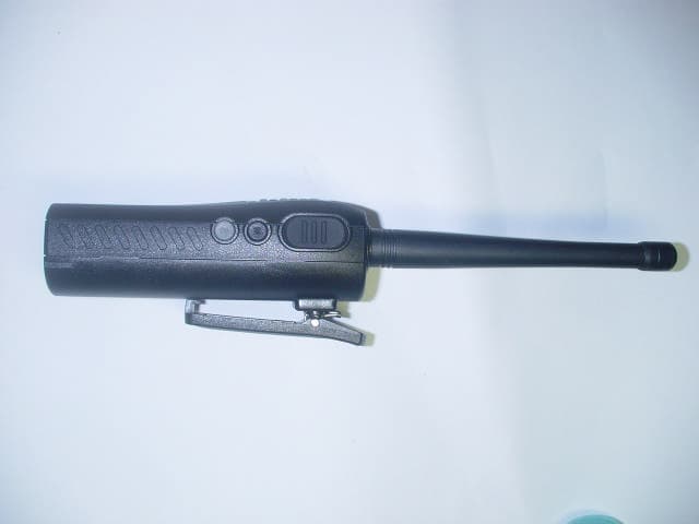
PM3GT10
Dec 08, 2004UHF LMRS TRANSMITTER
Equipment Class
TNF - Licensed Non-Broadcast Transmitter Held to Face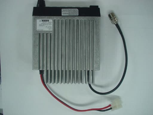
PM3MT900
Nov 28, 2004LAND MOBILE RADIO SERVICE GMRS TRANSMITTER
Equipment Class
TNB - Licensed Non-Broadcast Station Transmitter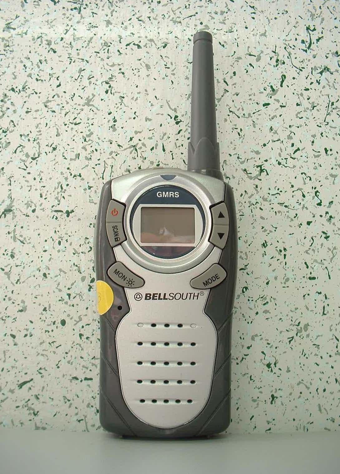
PM3GR5500
Jul 18, 2004GMRS/FRS UHF Transceiver
Equipment Class
FRF - Part 95 Family Radio Face Held Transmitter
PM3GX80
Jul 01, 2004Transceiver, VHF, PTT
Equipment Class
TNF - Licensed Non-Broadcast Transmitter Held to Face