PM3GR5500GMRS/FRS UHF Transceiver
Genex Telecom Co., Ltd.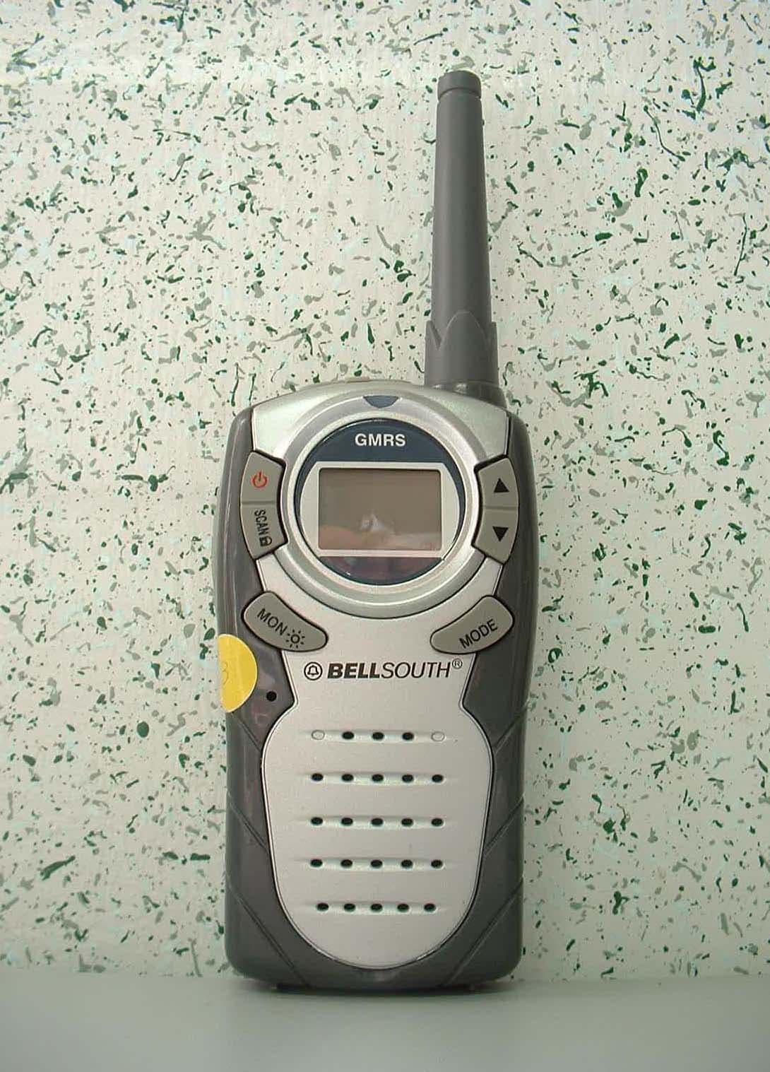
Click to zoom
Application Details
- Equipment Class
- FRF - Part 95 Family Radio Face Held Transmitter
- Date of Grant
- Jul 18, 2004
- Application Purpose
- Original Equipment
- Date of Application
- Jul 18, 2004
- Equipment Note
- GMRS/FRS UHF Transceiver
- Frequency Range
- 462.56250000 - 467.71250000
- Company
- Genex Telecom Co., Ltd.
- Country
- South Korea
Documents & Files
Document Text
Text extracted from the exhibit documents filed with the FCC. Open a document above to read the original.
Users Manual
GMRS-102B Basic Operation 04-06-09 1 of 6 1. General Specification - Power On/Off : Top - PTT Key : Side [ Tact SW ] - Monitor Key : Top - UP Key : Top - Down Key : Top - SCAN Key : Top - Function Key : Top - EXT Mic/Charge Jack[ 2.5φ ] - EXT Speaker Jack[ 3.5φ ] 2. Function Flow Chart z F Æ CHANNEL Æ BEEP Æ VOX Æ PWR Hi/Low Æ F 3. LCD Display GMRS-102B Basic Operation 04-06-09 2 of 6 4. Front, Side, Top Overview GMRS-102B Basic Operation 04-06-09 3 of 6 5. Operating Instruction 1) On/Off & Volume control Switch - Radio ON : Press power button. All indicators will appear momentarily on the LCD and you will hear short beep sound. - Radio Off : Press power button all indicators disappear on the LCD. - Volume setting : Press up[▲] or down[▼] button or adjust level that is most comfortable for you. 2) Setting the Channel GMRS-102B has 22 main channels. z To select the channel - Press Function[F] button once and channel digit will blink on the LCD. - Press up[▲] or down[▼] button to choose the channel. - Press the PTT button or Function[F] button to confirm 3) Beep AND Roger tone This feature will give the tone signal to other parties when transmitting finished (when PTT button is released.) z To activate or disable the beep tone - Press the Function[F] button until [rb on or oF] and the Roger [ ] icon blink on the LCD. - Press the up[▲] button or down [▼] button. - Press the PTT button or Function[F] button to confirm. 4) VOX (Voice Operated Transmission) This option enables you to have hands-free conversation. You do not have to operate the PTT button each time when you want to transmit. You can also choose the VOX sensitivity to suit your environment of operation. (Ex ; noisy road, motor bike, factory etc.) z To set the VOX mode. - Press the Function[F] button until the [ Uo 0 or x ] appears. 0 is a vox level - VOX icon will be appeared on the LCD. - Press the PTT button or Function[F] button to confirm. 5) Setting the Transmit Power HI/LO - HI : 1.5W TX power - LO : 500mW TX power z To set the TX output power - Press the Function[F] button until the [ Po LO or HI ] appears. GMRS-102B Basic Operation 04-06-09 4 of 6 - Press the up[▲] button or down [▼] button to set the TX power - Press the PTT button or Function[F] button to confirm. - HO or LO will appear on the LCD. - If the battery is in low condition, the TX Power will be switched to LO automatically. - Even though the TX power is set to HI. 6) Transmitting - Press and hold the PTT button (The "TX" LED will light with red color) - Speak slowly and clearly - To stop the transmission, release the PTT button - If there are no more receiving signal for 5 seconds, the unit will go into power save mode - and then the "TX" LED will blink with green color. 7) Receiving The coding feature reduces the possibility of interference and provides enhanced communication. You can only listen to a call that has correct matching code. Important ; Before transmitting or receiving to the other parties ; - Correct channel is selected ( 1 to 22 ) 8) Channel Scanning This feature allows you to monitor all activated channels while scanning. z To activate the Scan - Press the Scan[S] button - Radio will begin scanning. - When in scan mode, the display will show each scanning channel. - After an activated channel is scanned and received signal and then if there is no more signal, the scan will resume automatically. z To disable the Scan - Press the Scan[S] button, the unit will stop the scanning. - SCAN icon indicator will disappear from the LCD - The unit will return to home channel. 9) Call - Press and quickly release the PTT button twice, the TX and TX icons will be displayed on the - LCD Screen and a CALL TONE will be transmitted for 3~5 seconds. - (The "TX" LED will light with red color.) GMRS-102B Basic Operation 04-06-09 5 of 6 10) Monitoring the channel It is used for listening the week signal or to hear all activities on the channel by manually overriding channel setting. z To activate the Monitor feature - Press and hold the Monitor[Mon] button. (The monitor[ RX] icon will appear on the LCD.) z To disable the Monitor feature - Press the Monitor[Mon] button once. (The monitor[ RX] icon will disappear on the LCD.) 11) Keypad Lock The lock function is to avoid the accidental changes to channel with other radio settings. All buttons will be locked except the Power, PTT and monitor button. z To lock the keypad - Press and hold down the Scan[Scan] button for over 2 seconds. - Keypad will lock.( LOCK icon will appear on the LCD) z To unlock the keypad - Press and hold down the Scan[Scan] button for over 2 seconds. - Keypad will unlock. ( LOCK icon will disappear on the LCD) 12) Battery status indicator The Battery[ ] icon will blink when the radio is in low battery power. Charge the rechargeable battery or replace the batteries. - Full battery - Battery[ ] icon is not displayed. - Low battery - Battery[ ] icon is displayed. - Low battery warning – Battery[ ] icon will blinking. 13) External charger socket MIC socket can be used for the charging purpose. It should use the recommended rechargeable battery and wall charger. 14) External Speaker - Mic Use the approved accessories only to have the optimum performance. - Ear/Mic unit Normal Position: Hold the transmitter approximately 1” from your face and speak in a normal voice, with the antenna pointed up and away. GMRS-102B Basic Operation 04-06-09 6 of 6 Acknowledging Special Precautions and the FCC Notice Cautions. Modifications not expressly approved by the party responsible for compliance could void the user's authority to operate the equipment. FCC Information THIS DEVICE COMPLIES WITH PART 15 OF THE FCC RULES. OPERATION IS SUBJECT TO THE FOLLOWING TWO CONDITIONS : (1) THIS DEVICE MAU NOT CAUSE HARMFUL INTERFERENCE, AND (2) THIS DEVICE MUST ACCEPT ANY INTERFERENCE RECEIVED, INCLUDING INTERFERENCE THAT MAY CAUSE UNDERSIRED OPERATION. Safety Information For GMRS UNIT Your wireless handheld portable transcei…
Text truncated - open the document above for the full version.
Cover Letter(s)
6F FARMAX B/D 769-27 Bangbae-Dong, Seocho-Gu, Seoul, 137-830, KOREA June 14, 2004 Federal Communications Commission Equipment Authorization Branch 7435 Oakland Mills Road Columbia, MD 21046 LETTER OF AUTHORIZATION To whom it may concern: We, the undersigned, hereby authorize DIGITAL EMC Co., Ltd ., to act on our behalf in all manners relating to application for equipment authorization for model PM3GR5500 . including signing of all documents relating to these matters. Any and all acts carried out by DIGITAL EMC Co., Ltd., on our behalf shall have the same affect as acts of our own. This authorization is valid until further written notice from GENEX TELECOM CO., LTD. Sincerely, H. J. OH Management Planning Team/Planning Div.
Cover Letter(s)
6F FARMAX B/D 769-27 Bangbae-Dong, Seocho-Gu, Seoul, 137-830, KOREA June 14, 2004 Federal Communications Commission Equipment Authorization Branch 7435 Oakland Mills Road Columbia, MD 21046 In re : GENEX TELECOM CO., LTD. FCC ID : PM3GR5500 Request for Confidentiality Gentlemen: In accordance with 0.459 of CFR 47, GENEX TELECOM CO., LTD.. hereby requests confidentiality of the Block diagram, Schematics, Parts list and Operational description of the attached test report. These documents contain detailed system and equipment description and related information about the product which GENEX TELECOM CO., LTD. considers to be proprietary, confidential, and a custom design and, otherwise, would not release to the general public. Since this design is a basis from which future technological products will evolve, GENEX TELECOM CO., LTD. considers that this information would be of benefit to its competitors, and that the disclosure of the information in these documents would give competitors an unfair advantage in the market. Sincerely, H. J. OH Management Planning Team/Planning Div.
Cover Letter(s)
6F FARMAX B/D 769-27 Bangbae-Dong, Seocho-Gu, Seoul, 137-830, KOREA June 14, 2004 Federal Communications Commission Equipment Authorization Branch 7435 Oakland Mills Road Columbia, MD 21046 In re : GENEX TELECOM CO., LTD. FCC ID : PM3GR5500 15.19 statement request Gentlemen: Because The device is so small that it is not practicable to place the statement specified under 15.19 statement request, the information required by this paragraph shall be placed in a prominent location in the user's manual. Sincerely, H. J. OH Management Planning Team/Planning Div
External Photos
FCC ID: PM3GR5500 Copyright Ⓒ 2004, DIGITAL EMC Co., Ltd. View 1 FCC ID: PM3GR5500 Copyright Ⓒ 2004, DIGITAL EMC Co., Ltd. View 2 FCC ID: PM3GR5500 Copyright Ⓒ 2004, DIGITAL EMC Co., Ltd. View 3 FCC ID: PM3GR5500 Copyright Ⓒ 2004, DIGITAL EMC Co., Ltd. View 4 FCC ID: PM3GR5500 Copyright Ⓒ 2004, DIGITAL EMC Co., Ltd. View 5-1 FCC ID: PM3GR5500 Copyright Ⓒ 2004, DIGITAL EMC Co., Ltd. View 5-2 FCC ID: PM3GR5500 Copyright Ⓒ 2004, DIGITAL EMC Co., Ltd. View 6
ID Label/Location Info
FCC ID: PM3GR5500 FCC ID SAMPLE LABEL & LOCATION LABELLING REQUIREMENTS PER §2.925 The Label shown shall be permanently affixed at a conspicuous location on the device and be readily visible to the user at the time of purchase (SEE NEXT PAGE) FCC ID: PM3GR5500 APPENDIX - 1 FCC ID: PM3GR5500 Model No.: GMRS102B Serial Number: Caution: See instruction manual for specific operating requirements.
Internal Photos
FCC ID: PM3GR5500 Copyright Ⓒ 2004, DIGITAL EMC Co., Ltd. View 1 FCC ID: PM3GR5500 Copyright Ⓒ 2004, DIGITAL EMC Co., Ltd. View 2 FCC ID: PM3GR5500 Copyright Ⓒ 2004, DIGITAL EMC Co., Ltd. View 3 FCC ID: PM3GR5500 Copyright Ⓒ 2004, DIGITAL EMC Co., Ltd. View 4 FCC ID: PM3GR5500 Copyright Ⓒ 2004, DIGITAL EMC Co., Ltd. View 5
RF Exposure Info
DEMC#DR50110407B Copyright ○ c 2004, DIGITAL EMC Co., Ltd. Page 1 of 22 683-3, Yubang-Dong, Yongin-Si, Kyunggi-Do, Korea. 449-080 Tel: +82-31-321-2664 Fax: +82-31-321-1664 http://www.digitalemc.com SAR TEST REPORT Dates of Tests: June 30, 2004 Test Report S/N:DR50110407B Test Site : DIGITAL EMC CO., LTD. FCC ID APPLICANT FCC Classification: General Mobile(/Family) Radio Services (GMRS/FRS) EUT Type: UHF Transceiver Test Device Serial No.: Identical prototype Frequency Range: 462.5625 ~ 467.7125MHz Rule Part(s): §2.1093; FCC/OET Bulletin Supplement C[July 2001] Max.RF Output Power: 1.39W for High power(ERP) / 0.49W for Low power (ERP) Max. SAR Measurement: 0.209W/kg FM Face SAR, 0.498W/kg FM Body SAR (50% Duty cycle) Model(s): GMRS-102B Tested Channel number: Ch. 22 (462.7250MHz) Application Type: Certification Data of issue June 30, 2004 D.M.JUNG (Manager) This wireless portable device has been shown to be capable of compliance for localized specific absorption rate (SAR) for uncontrolled environment/general population exposure limits specified in ANSI/IEEE Std. C95.1-1992 and had been tested in accordance with the measurement procedures specified in FCC/OET Bulletin 65 Supplement C (2001) and IEEE Std. 1528-200X (Draft 6.4, July 2001). I attest to the accuracy of data. All measurements reported herein were performed by me or were made under my supervision and are correct to the best of my knowledge and belief. I assume full responsibility for the completeness of these measurements and vouch for the qualifications of all persons taking them. PM3GR5500 GENEX TELECOM CO., LTD. DEMC#DR50110407B Copyright ○ c 2004, DIGITAL EMC Co., Ltd. Page 2 of 22 1. INTRODUCTION .................................................................................................................... 3 SAR DEFINITION .................................................................................................................. 3 2. SAR MEASUREMENT SETUP.................................................................................................. 4 Robotic System............................................................................................................................. 4 System Hardware ......................................................................................................................... 4 System Electronics........................................................................................................................ 4 3. DASY3 E-FIELD PROBE SYSTEM........................................................................................... 5 Probe Measurement System.......................................................................................................... 5 Probe Specifications ..................................................................................................................... 5 4. Probe Calibration Process............................................................................................................. 6 Dosimetric Assessment Procedure................................................................................................ 6 Free Space Assessment ................................................................................................................ 6 Temperature Assessment ............................................................................................................. 6 5. PHANTOM & EQUIVALENT TISSUES.................................................................................... 7 SAM Phantom ............................................................................................................................. 7 Brain & Muscle Simulating Mixture Characterization ................................................................ 7 Device Holder for Transmitters.................................................................................................... 7 6. TEST SYSTEM SPECIFICATIONS............................................................................................ 8 Automated Test System Specifications......................................................................................... 8 7. DOSIMETRIC ASSESSMENT & PHANTOM SPECS ............................................................. 9 Measurement Procedure................................................................................................................ 9 Specific Anthropomorphic Mannequin (SAM) Specifications..................................................... 9 8. DEFINITION OF REFERENCE POINTS .................................................................................. 10 EAR Reference Point.................................................................................................................... 10 Handset Reference Points............................................................................................................. 10 9. TEST CONFIGURATION POSITIONS ..................................................................................... 11 Positioning for Cheek/Touch ....................................................................................................... 11 Positioning for Ear /15° Tilt ......................................................................................................... 12 Body Holster /Belt Clip Configurations ....................................................................................... 13 10. ICNIRP GUIDELINES RF EXPOSURE LIMITS..................................................................... 14 Uncontrolled Environment ........................................................................................................... 14 Controlled Environment................................................................................................................ 14 11. MEASUREMENT UNCERTAINTIES...................................................................................... 15 SAR Measurement Uncertainties ..…
Text truncated - open the document above for the full version.
RF Exposure Info
GENEX SAM(835MHz) Phantom; Flat Section; Probe: ET3DV6 - SN1702; ConvF(7.60,7.60,7.60); 450MHz Body: σ = 0.98 mho/m ε r = 57.2 ρ = 1.00 g/cm 3 ; Crest factor: 1.0; SAR (1g): 0.987 mW/g, SAR (10g): 0.674 mW/g; GENEX TELECOM FCC ID: PM3GR5500 FM Mode, Ch. 22[462.5625MHz] ; Standard Battery ; Ambient Temp = 23 °C /Meas. Tissue Temp. = 22 °C Power = 0.5W ; Spacing = 0cm From Belt Clip to flat phantom ; Antenna Fixed Test Date -- June 30. 2004 [FCC/OET Bulletin65 - Supplement C, July 2001] SAR Tot [mW/g] 9.95E-21.99E-12.98E-13.98E-14.97E-15.97E-16.97E-17.96E-18.95E-19.95E-1 <DIGITAL EMC> GENEX SAM(835MHz) Phantom; Flat Section; Probe: ET3DV6 - SN1702; ConvF(7.60,7.60,7.60); 450MHz Body: σ = 0.98 mho/m ε r = 57.2 ρ = 1.00 g/cm 3 ; Crest factor: 1.0; SAR (1g): 0.995 mW/g, SAR (10g): 0.679 mW/g; GENEX TELECOM FCC ID: PM3GR5500 FM Mode, Ch. 22[462.5625MHz] ; Standard Battery ; Ambient Temp = 23 °C /Meas. Tissue Temp. = 22 °C Power = 1.5W ; Spacing = 0cm From Belt Clip to flat phantom ; Antenna Fixed Test Date -- June 30. 2004 [FCC/OET Bulletin65 - Supplement C, July 2001] SAR Tot [mW/g] 9.60E-21.92E-12.88E-13.84E-14.80E-15.76E-16.72E-17.68E-18.64E-19.60E-1 <DIGITAL EMC> GENEX SAM(835MHz) Phantom; Section; Probe: ET3DV6 - SN1702; ConvF(7.60,7.60,7.60); 450MHz Body: σ = 0.98 mho/m ε r = 57.2 ρ = 1.00 g/cm 3 ; Crest factor: 1.0; ; GENEX TELECOM FCC ID: PM3GR5500 FM Mode, Ch. 22[462.5625MHz] ; Standard Battery ; Ambient Temp = 21 °C /Meas. Tissue Temp. = 22 °C Power = 1.5W ; Spacing = 0cm From Belt Clip to flat phantom ; Antenna Fixed Test Date -- June 30. 2004 [FCC/OET Bulletin65 - Supplement C, July 2001] <DIGITAL EMC> 0.00.20.40.60.81.01.21.41.6 0 1020304050 SAR tot [mW/g] [mm] GENEX SAM(835MHz) Phantom; Flat Section; Probe: ET3DV6 - SN1702; ConvF(7.70,7.70,7.70); 450MHz Face: σ = 0.90 mho/m ε r = 45.2 ρ = 1.00 g/cm 3 ; Crest factor: 1.0; SAR (1g): 0.305 mW/g, SAR (10g): 0.209 mW/g; GENEX TELECOM FCC ID: PM3GR5500 FM Mode, Ch. 22[462.5625MHz] ; Standard Battery ; Ambient Temp = 23 °C /Meas. Tissue Temp. = 22 °C Power = 0.5W ; Spacing = 2.5cm From ANT to flat phantom ; Antenna Fixed Test Date -- June 30. 2004 [FCC/OET Bulletin65 - Supplement C, July 2001] SAR Tot [mW/g] 3.16E-26.32E-29.48E-21.26E-11.58E-11.90E-12.21E-12.53E-12.84E-13.16E-1 <DIGITAL EMC> GENEX SAM(835MHz) Phantom; Flat Section; Probe: ET3DV6 - SN1702; ConvF(7.70,7.70,7.70); 450MHz Face: σ = 0.90 mho/m ε r = 45.2 ρ = 1.00 g/cm 3 ; Crest factor: 1.0; SAR (1g): 0.417 mW/g, SAR (10g): 0.290 mW/g * Max outside; GENEX TELECOM FCC ID: PM3GR5500 FM Mode, Ch. 22[462.5625MHz] ; Standard Battery ; Ambient Temp = 23 °C /Meas. Tissue Temp. = 22 °C Power = 1.5W ; Spacing = 2.5cm From ANT to flat phantom ; Antenna Fixed Test Date -- June 30. 2004 [FCC/OET Bulletin65 - Supplement C, July 2001] SAR Tot [mW/g] 4.71E-29.42E-21.41E-11.88E-12.35E-12.83E-13.30E-13.77E-14.24E-14.71E-1 <DIGITAL EMC> GENEX SAM(835MHz) Phantom; Section; Probe: ET3DV6 - SN1702; ConvF(7.70,7.70,7.70); 450MHz Face: σ = 0.90 mho/m ε r = 45.2 ρ = 1.00 g/cm 3 ; Crest factor: 1.0; ; GENEX TELECOM FCC ID: PM3GR5500 FM Mode, Ch. 22[462.5625MHz] ; Standard Battery ; Ambient Temp = 23 °C /Meas. Tissue Temp. = 22 °C Power = 1.5W ; Spacing = 2.5cm From ANT to flat phantom ; Antenna Fixed Test Date -- June 30. 2004 [FCC/OET Bulletin65 - Supplement C, July 2001] <DIGITAL EMC> 0.00.10.20.30.40.50.6 0 1020304050 SAR tot [mW/g] [mm]
Test Report
PROBE CALIBRATION DIGITAL EMC
Test Report
450MHz Dipole Validation SAM(835M) Phantom; Flat Section; Probe: ET3DV6-SN1702; ConvF(7.60,7.60,7.60); Med. parameter 450 MHz Muscle: σ = 0.98 mho/m ε r = 57.2 ρ = 1.00 g/cm 3 ; Crest factor: 1.0; SAR (1g): 1.27 mW/g, SAR (10g): 0.824 mW/g; Dipole validation: for f < 1 GHz, distance to the liquid d = 15 mm for f > 1 GHz, distance to the liquid d=10 mm Test Date -- June 30. 2004 SAR Tot [mW/g] 1.45E-12.89E-14.34E-15.79E-17.24E-18.68E-11.01E+01.16E+01.30E+01.45E+0 <DIGITAL EMC>
Test Setup Photos
FCC ID: PM3GR5500 Copyright Ⓒ 2004, DIGITAL EMC Co., Ltd. View 1 FCC ID: PM3GR5500 Copyright Ⓒ 2004, DIGITAL EMC Co., Ltd. View 2 FCC ID: PM3GR5500 Copyright Ⓒ 2004, DIGITAL EMC Co., Ltd. View 3 FCC ID: PM3GR5500 Copyright Ⓒ 2004, DIGITAL EMC Co., Ltd. View 4
Test Setup Photos
FCC ID: PM3GR5500 Copyright Ⓒ 2004, DIGITAL EMC Co., Ltd. View 1 FCC ID: PM3GR5500 Copyright Ⓒ 2004, DIGITAL EMC Co., Ltd. View 2 FCC ID: PM3GR5500 Copyright Ⓒ 2004, DIGITAL EMC Co., Ltd. View 3 FCC ID: PM3GR5500 Copyright Ⓒ 2004, DIGITAL EMC Co., Ltd. View 3
Contact Information
Applicant
Clark Cheon(Manager)
Technical Specifications
| # | Rule Parts | Frequency Range | Power Output | Emission | Tolerance |
|---|---|---|---|---|---|
| 3 | 95B | 462.5625 MHz - 467.7125 MHz | 490.00 mW | 11K0F3E | 2.5 ppm |
Other Applications from Genex Telecom Co., Ltd.
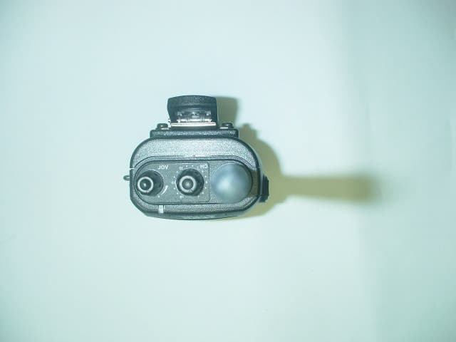
PM3GT40
Dec 08, 2004UHF LMRS TRANSMITTER
Equipment Class
TNF - Licensed Non-Broadcast Transmitter Held to Face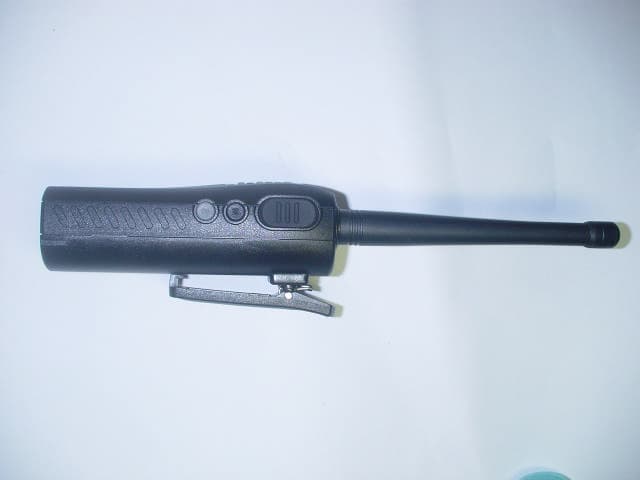
PM3GT10
Dec 08, 2004UHF LMRS TRANSMITTER
Equipment Class
TNF - Licensed Non-Broadcast Transmitter Held to Face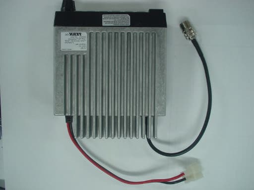
PM3MT900
Nov 28, 2004LAND MOBILE RADIO SERVICE GMRS TRANSMITTER
Equipment Class
TNB - Licensed Non-Broadcast Station Transmitter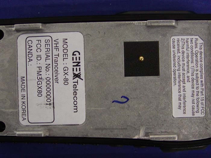
PM3GX80
Jul 01, 2004Transceiver, VHF, PTT
Equipment Class
TNF - Licensed Non-Broadcast Transmitter Held to Face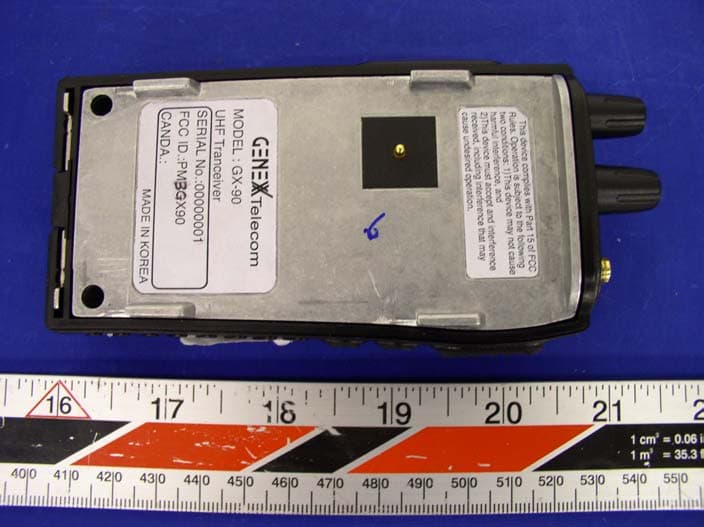
PM3GX90
Apr 05, 2004Transceiver, UHF, PTT
Equipment Class
TNF - Licensed Non-Broadcast Transmitter Held to Face