PM3MT900LAND MOBILE RADIO SERVICE GMRS TRANSMITTER
Genex Telecom Co., Ltd.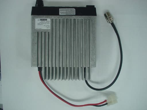
Click to zoom
Application Details
- Equipment Class
- TNB - Licensed Non-Broadcast Station Transmitter
- Date of Grant
- Nov 28, 2004
- Application Purpose
- Original Equipment
- Date of Application
- Nov 28, 2004
- Equipment Note
- LAND MOBILE RADIO SERVICE GMRS TRANSMITTER
- Frequency Range
- 440.00000000 - 474.00000000
- Company
- Genex Telecom Co., Ltd.
- Country
- South Korea
Documents & Files
Document Text
Text extracted from the exhibit documents filed with the FCC. Open a document above to read the original.
Users Manual
OPERATING FEATURE 1 DISCRIPTION OF CONTROLS FRONT COVER TOP COVER 1 ANTENNA CONNECTOR 2 EXTERNAL SPEAKER JACK 3 INTERNAL SPEAKER 4 UP KEY 5 DOWN KEY 6 MIC 7 MONITOR KEY 8 MODE KEY 9 SECR KEY 10 T/A KEY 11 HOME KEY 12 SCAN KEY 13 DUAL LED INDICATOR 14 VOLUME SWITCH 15 DISPLAY LCD DISPLAY FUNCTIONS CTCSS/CDCSS The MT-900 series in the conventional mode will be capable of all 38 TIA/EIA CTCSS tones, plus up to 11 non-standard CTCSS tones. The MT-900 series will be capable of all TIA/EIA CDCSS codes, normal and inverted. Channels The radio will be programmable for up to 32 channels. How the channels are distributed is dependent on Dealer PC Programming. Talk Around Talk around is accomplished via the “T/A” button. This feature is dealer programmable on a per channel basis if T/A is to be used or recalled during radio power up. External Option Port/Connector The MT-900 series will be capable of sending and receiving data information via a high density 15 connector located at the back of the radio. The high density 15 is to be wired to the option interface internal to the radio and have the following ports: 1. Audio Output 2. TX Tone 3. Busy/SQ 4. Call 5. Monitor 6. PTT 7. RX_Audio_In 8. Alert Tone 9. Call LED 10. MIC Control 11. Audio Mute 12. TX Enable 13. Ground 14. SWB+_Out 15. Horn P/C Programming The MT-900 series will be capable of PC programming through the microphone jack for radio operational parameters. 2-Tone Decode The 2-tone decode capability shall be done in software and will not require an external option board. The Motorola and GE format shall be used. This option shall be available on the dealer PC programming. ANI The Automatic Number Identification (ANI) capability shall be done in software and will not require an external option board. The ANI function will be capable of being programmed per each individual conventional System. The ANI DTMF will be up to 16 digits, numbers 0-9 and characters ?, #. The ANI will be programmable to be sent upon PTT or release of PTT. Time-Out Timer The MT-800 series is to have a programmable transmit time out timer. Five seconds before time out occurs, the radio sounds an alert tone and be displayed as “ TOT”. Five seconds later, another alert tone is heard, this time disabling the transmitter. When TX inhibit is used in conjunction with the time out timer, the radio will not be able to transmit for a programmed period of time after time out occurs. An alternating high and low tone is heard if PTT is depressed while in TX inhibit mode. When TX inhibit time has expired, an alert tone is heard and TX can resume. The TX time-out timer is programmable from 10 to 990 sec. Public Address Mode (PA) Allows operator to enable an external speaker and transmit microphone audio only. If feasible this option should perform an intercom mode between multiple control heads, microphone audio only. Programmable Hook The microphone is to be dealer programmable for hook function by mechanical ground or software. Nuisance Delete A channel can be temporarily deleted by entering the monitor key for conventional operation while topped on the channel to be deleted. The channel will remain inactive until radio power is reset. Busy Channel Lock-Out/Marked Idle When enabled and the channel is busy a transmission will not be allowed until the channel is clear. When marked idle is enabled if the correct programmed tone is received in conjunction with busy channel lock out a transmission will be allowed. This is for conventional radio operation only. Minimum/Maximum Volume/Alerts All audible tones and alerts are to be variable with the volume control of the radio. FCC Information This device complies with part 15 of the FCC rules. Operation is subject to the following two conditions: (1) this device may not cause harmful interference, and (2) this device must accept any interference received, including interference that may cause undesired operation. FCC RF Exposure Compliance This equipment generates uses and can radiate radio frequency energy and, if not installed and used in accordance with the instructions, may cause harmful interference. This unit does not contain any user serviceable parts and repairs should only be made by authorized service personnel. This equipment complies with FCC RF radiation exposure limits set forth for controlled and uncontrolled environments. It is required that the radiating antenna be mounted out of range of personnel (at least 46 centimeters from users and 102 centimeters from the general population) to conform to the requirements of ANSI/IEEE C95.1-1992 Standard for Safety Levels with Respect to Human Exposure to Radio Frequency Electromagnetic Fields. This separation distance requires the radiating antenna be mounted to the center of the roof top of vehicles. In addition to this, the operator must cease transmissions when persons are within the safe distance of the antenna. Power listed for this device is conducted. This device must be restricted to work related operations in an Occupational/Controlled RF exposure Environment. End-Users must be provided with the specific training information. All qualified end-users of this device must have the knowledge to control their exposure conditions and/or duration to comply with Occupational/Controlled limit and requirements.
Cover Letter(s)
November 3, 2004 Timco Engineering Inc. 849 NW State Road 45 Newberry, FL 32669 Telephone 888.472.2424 Fax 352.472.2030 Applicant: Genex Telecom Co. LTD 6FL Farmax Building 796-27 Bangbae-Dong, Seocho-Gu SEOUL 137-060 SOUTH KOREA FRN 0006-1433-33 Re: Confidentiality of schematics Equipment: LMRS / GMRS Transceiver FCC ID: PM3 MT 900 Gentlemen: It is requested that the information contained in the block diagrams, operational description, parts list, and schematics of the application be held confidential per Section 0.459. Please use this information in obtaining a grant of certification for the transceiver, for use in the land mobile radio service and general mobile radio service, model number MT 900. In support of this request, we submit the following: 1. Identification of the specific information for which confidential treatment is sought: The materials set fourth in the Operational Description, Block Diagram, Parts List, Internal PCB layout exhibit, and Schematics, are those for which confidentiality is sought. 2. Identification of the Commission proceeding in which the information was submitted or a description of the circumstances giving rise to the submission: The proceeding is that involving the application for equipment authorization (certification) under FCC ID No: PM3 MT 900 3. Explanation of the degree to which the information is commercial or financial, or contains a trade secret or is privileged: This material includes a detailed theory of operation and circuit diagrams, (schematics, part list, PCB layout diagrams, and Block diagrams). As such this material is treated as highly confidential business information and is not subject to public view. Should you require any further information, please contact the undersigned. Thank you for your consideration in this matter. Sincerely, Scot Rogers Rogers Labs, Inc. ROGERS LABS, INC. 4405 West 259 th Terrace Louisburg, KS 66053 Phone / Fax (913) 837-3214
External Photos
ROGERS LABS, INC. Genex Telecom Co. LTD 4405 West 259 th Terrace MODEL: MT-900 LMRS/GMRS UHF Transceiver Louisburg, KS 66053 Test #:040922 FCC ID#: PM3 MT900 SN: Set 1 Phone/Fax: (913) 837-3214 Test to: FCC Parts 2, 15, 90 and 95 Page 1 of 2 Genex PM3MT900 ExtPho.doc 10/25/04 External Photos of PM3 MT900. ROGERS LABS, INC. Genex Telecom Co. LTD 4405 West 259 th Terrace MODEL: MT-900 LMRS/GMRS UHF Transceiver Louisburg, KS 66053 Test #:040922 FCC ID#: PM3 MT900 SN: Set 1 Phone/Fax: (913) 837-3214 Test to: FCC Parts 2, 15, 90 and 95 Page 2 of 2 Genex PM3MT900 ExtPho.doc 10/25/04
ID Label/Location Info
ROGERS LABS, INC. Genex Telecom Co. LTD 4405 West 259 th Terrace MODEL: MT-900 LMRS/GMRS UHF Transceiver Louisburg, KS 66053 Test #:040922 FCC ID#: PM3 MT900 SN: Set 1 Phone/Fax: (913) 837-3214 Test to: FCC Parts 2, 15, 90 and 95 Page 1 of 3 Genex PM3MT900 Labels.doc 11/13/04 FCC ID label and location for PM3 MT900. RF Safety information label. All qualified end-users of this device must have the knowledge to control their exposure conditions an/or duration to comply with Occupational/Controlled limit and requirements. TEKK INC. Model: MT-900 UHF FM Transceiver Power source DC 13.8 V (Fuse 12A) Serial No: LDJXXXXX FCC ID: PM3 MT900 IC No: 4439A-MT-900 Made in Korea Part 15 and RF Safety information label
Internal Photos
ROGERS LABS, INC. Genex Telecom Co. LTD 4405 West 259 th Terrace MODEL: MT-900 LMRS/GMRS UHF Transceiver Louisburg, KS 66053 Test #:040922 FCC ID#: PM3 MT900 SN: Set 1 Phone/Fax: (913) 837-3214 Test to: FCC Parts 2, 15, 90 and 95 Page 1 of 2 Genex MT900 IntPho 2 11/13/2004 Internal Photographs of PM3MT900. ROGERS LABS, INC. Genex Telecom Co. LTD 4405 West 259 th Terrace MODEL: MT-900 LMRS/GMRS UHF Transceiver Louisburg, KS 66053 Test #:040922 FCC ID#: PM3 MT900 SN: Set 1 Phone/Fax: (913) 837-3214 Test to: FCC Parts 2, 15, 90 and 95 Page 2 of 2 Genex MT900 IntPho 2 11/13/2004
RF Exposure Info
ROGERS LABS, INC. Genex Telecom Co. LTD 4405 West 259 th Terrace MODEL: MT-900 LMRS/GMRS UHF Transceiver Louisburg, KS 66053 Test #:040922 FCC ID#: PM3 MT900 SN: Set 1 Phone/Fax: (913) 837-3214 Test to: FCC Parts 2, 15, 90 and 95 Page 1 of 2 Genex PM3MT900 RF Exp.doc 10/26/2004 General The MT900 is a LMRS/GMRS, UHF transceiver which is mobile mounted with radiating antenna mounted outside the vehicle and transmitting with output power less than 40 Watts. Per table 1 of 1.1307, paragraphs 1.1310 and 2.1091 of CFR 47, evaluation for this device is as follows. Due to the location of the antenna, normal operating conditions and use, the unit will satisfy the requirements for RF Exposure. Calculations are made here for completeness. SPECIFIC ABSORPTION RATE CALCULATION Calculations per 2.1091 of CFR 47. These calculations are based upon a typical human figure as approximated below. The height is 5’ 8” (173 cm.) and the weight is 160 lbs. (72.6kg). The calculated absorption cross section for this figure is 143 cm squared. CALCULATED OCCUPATIONAL / CONTROLLED POPULATION SAR S = PG/(4?R 2 )? Where S = power density in mw/cm 2 P = input power to antenna in mw. G = power gain of antenna R = distance from antenna in cm. For a minimum distance of 46 centimeters and 40.0 watts (40,000 mW) operation with the supplied antenna, S is: S = 40000(1)/(4?(46) 2 ) = 1.5043 mw/cm 2 For a body cross sectional area of 143 cm squared, (1.5043)(143) = 215.11 mw is absorbed. For a body mass of 72.6 kg, this is 215.11/72.6 = 2.96 mw/kg = 0.003 w/kg Calculations demonstrating compliance with CFR 47 paragraphs 1.1310 and 2.1091 are show below. ROGERS LABS, INC. Genex Telecom Co. LTD 4405 West 259 th Terrace MODEL: MT-900 LMRS/GMRS UHF Transceiver Louisburg, KS 66053 Test #:040922 FCC ID#: PM3 MT900 SN: Set 1 Phone/Fax: (913) 837-3214 Test to: FCC Parts 2, 15, 90 and 95 Page 2 of 2 Genex PM3MT900 RF Exp.doc 10/26/2004
Test Report
TEST REPORT For APPLICATION of CERTIFICATION For Genex Telecom Co. LTD 6FL Farmax Building 796-27 Bangbae-Dong, Seocho-Gu SEOUL 137-060 SOUTH KOREA Mr. John Ryu President MODEL: MT-900 Land Mobile and General Mobile Radio Services (LMRS/GMRS) UHF TRANSCEIVER FREQUENCY: 440 - 474 MHz FCC ID: PM3 MT 900 Test Date: September 22, 2004 Certifying Engineer: Scot D. Rogers ROGERS LABS, INC. 4405 West 259th Terrace Louisburg, KS 66053 Phone: (913) 837-3214 FAX: (913) 837-3214 This report shall not be reproduced except in full, without the written approval of the laboratory. This report must not be used by the client to claim product endorsement by NVLAP or any agency of the U.S. Government. ROGERS LABS, INC. 4405 West 259 th Terrace Louisburg, KS 66053 Phone / Fax (913) 837-3214 NVLAP Accredited Laboratory NVLAP Lab Code: 200087-0 ROGERS LABS, INC. Genex Telecom Co. LTD 4405 West 259 th Terrace MODEL: MT-900 LMRS/GMRS UHF Transceiver Louisburg, KS 66053 Test #:040922 FCC ID#: PM3 MT 900 SN: Set 1 Phone/Fax: (913) 837-3214 Test to: FCC Parts 2, 15, 90 and 95 Page 2 of 31 CERTIFICATION\Genex MT900 TestRpt 11/13/2004 TABLE OF CONTENTS FORWARD: 3 LIST OF TEST EQUIPMENT 3 2.1033(C) APPLICATION FOR CERTIFICATION 4 2.1046 RF POWER OUTPUT 5 Measurements Required: 5 Test Arrangement: 5 Results: 6 2.1047 MODULATION CHARACTERISTICS 6 Measurements Required: 6 Test Arrangement: 6 Results: 7 2.1049 OCCUPIED BANDWIDTH 9 Measurements Required: 9 Test Arrangement: 9 Results: 10 2.1051 SPURIOUS EMISSIONS AT ANTENNA TERMINALS 14 Measurements Required: 14 Test Arrangement: 14 Results: 17 2.1053 FIELD STRENGTH OF SPURIOUS RADIATION 18 Measurements Required: 18 Test Arrangement: 18 Results: 20 2.1055 FREQUENCY STABILITY 22 Measurements Required: 22 Test Arrangement: 22 Results: 23 TRANSIENT FREQUENCY BEHAVIOR, PER 90.214 24 Test Arrangement: 25 Measurement Data : 26 APPENDIX 28 NVLAP Accredited Laboratory NVLAP Lab Code: 200087-0 ROGERS LABS, INC. Genex Telecom Co. LTD 4405 West 259 th Terrace MODEL: MT-900 LMRS/GMRS UHF Transceiver Louisburg, KS 66053 Test #:040922 FCC ID#: PM3 MT 900 SN: Set 1 Phone/Fax: (913) 837-3214 Test to: FCC Parts 2, 15, 90 and 95 Page 3 of 31 CERTIFICATION\Genex MT900 TestRpt 11/13/2004 FORWARD: In accordance with the Federal Communications Code of Federal Regulations, dated October 1, 2003, Part 2 Subpart J, Paragraphs 2.907, 2.911, 2.913, 2.915, 2.925, 2.926, 2.1031 through 2.1057, applicable paragraphs of Parts 15, 90, and 95, the following is submitted: List of Test Equipment A Hewlett Packard 8591EM and or 8562A Spectrum Analyzer was used as the measuring device for the emissions testing. The analyzer settings used are described in the following table. Refer to the Appendix for a complete list of Test Equipment. HP 8591EM SPECTRUM ANALYZER SETTINGS CONDUCTED EMISSIONS: RBW AVG. BW DETECTOR FUNCTION 9 kHz 30 kHz Peak/Quasi Peak RADIATED EMISSIONS (30 – 1000 MHz): RBW AVG. BW DETECTOR FUNCTION 120 kHz 300 kHz Peak/Quasi Peak HP 8562A SPECTRUM ANALYZER SETTINGS RADIATED EMISSIONS (1 – 40 GHz): RBW AVG. BW DETECTOR FUNCTION 1 MHz 1 MHz Peak/Average ANTENNA CONDUCTED EMISSIONS: RBW AVG. BW DETECTOR FUNCTION 120 kHz 300 kHz Peak NVLAP Accredited Laboratory NVLAP Lab Code: 200087-0 ROGERS LABS, INC. Genex Telecom Co. LTD 4405 West 259 th Terrace MODEL: MT-900 LMRS/GMRS UHF Transceiver Louisburg, KS 66053 Test #:040922 FCC ID#: PM3 MT 900 SN: Set 1 Phone/Fax: (913) 837-3214 Test to: FCC Parts 2, 15, 90 and 95 Page 4 of 31 CERTIFICATION\Genex MT900 TestRpt 11/13/2004 2.1033(c) Application for Certification (1) Manufacturer: Genex Telecom Co. LTD 6FL Farmax Building 796-27 Bangbae-Dong, Seocho-Gu SEOUL 137-060 SOUTH KOREA (2) Identification: Model: MT-900 S/N: Set 1 FCC I.D.: PM3 MT 900 (3) Instruction Book: Refer to exhibit for Draft Instruction Manual. (4) Emission Type: 11k25F3E wideband and 6k06F3E Narrow band (5) Frequency Range: 440 to 474 MHz (6) Operating Power Level: 40 Watts (High Power) 5 Watts (Low Power) (7) Max P o : 40 Watts (8) Power into final amplifier: 110.4 Watts (13.8V @ 8A) (9) Tune Up Procedure for Output Power: Refer to Exhibit for Transceiver Alignment Procedure. (10) Circuit Diagrams; description of circuits, frequency stability, spurious suppression, and power and modulation limiting: Refer to Exhibit for Circuit Diagrams. Refer to Exhibit for Theory of Operation. (11) Photograph or drawing of the Identification Plate: Refer to Exhibit for Photograph or Drawing. (12) Drawings of Construction and Layout: Refer to Exhibit for Drawings of Components Layout and Chassis Drawings. (13) Detail Description of Digital Modulation: Not applicable. NVLAP Accredited Laboratory NVLAP Lab Code: 200087-0 ROGERS LABS, INC. Genex Telecom Co. LTD 4405 West 259 th Terrace MODEL: MT-900 LMRS/GMRS UHF Transceiver Louisburg, KS 66053 Test #:040922 FCC ID#: PM3 MT 900 SN: Set 1 Phone/Fax: (913) 837-3214 Test to: FCC Parts 2, 15, 90 and 95 Page 5 of 31 CERTIFICATION\Genex MT900 TestRpt 11/13/2004 2.1046 RF Power Output Measurements Required: Measurements shall be made to establish the radio frequency power delivered by the transmitter into the standard output termination. The power output shall be monitored and recorded and no adjustment shall be made to the transmitter after the test has begun, except as noted below: If the power output is adjustable, measurements shall be made for the highest and lowest power levels. Test Arrangement: The radio frequency power output was measured at the antenna terminal by replacing the antenna with a spectrum analyzer and appropriate attenuation. The spectrum analyzer had an impedance of 50W to match the impedance of the standard antenna. A HP 8591EM Spectrum Analyzer was used to measure the radio frequency power at the antenna port. The data was taken in dBm and converted to watts as shown in the following Table. Data was taken per Paragraph 2.1046(a) and applicable parts of Parts 2, 90, and 95. Power in dBm was converted to power in Watts using the follow…
Text truncated - open the document above for the full version.
Contact Information
Applicant
Clark Cheon(Manager)
Test Firm
Rogers Labs, Inc.Scot Rogers
Technical Specifications
| # | Rule Parts | Frequency Range | Power Output | Emission | Tolerance |
|---|---|---|---|---|---|
| 4 | 90,95A | 440 MHz - 474 MHz | 5 W | 13K8F3E | 1.3 ppm |
Other Applications from Genex Telecom Co., Ltd.

PM3GT40
Dec 08, 2004UHF LMRS TRANSMITTER
Equipment Class
TNF - Licensed Non-Broadcast Transmitter Held to Face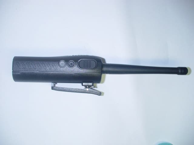
PM3GT10
Dec 08, 2004UHF LMRS TRANSMITTER
Equipment Class
TNF - Licensed Non-Broadcast Transmitter Held to Face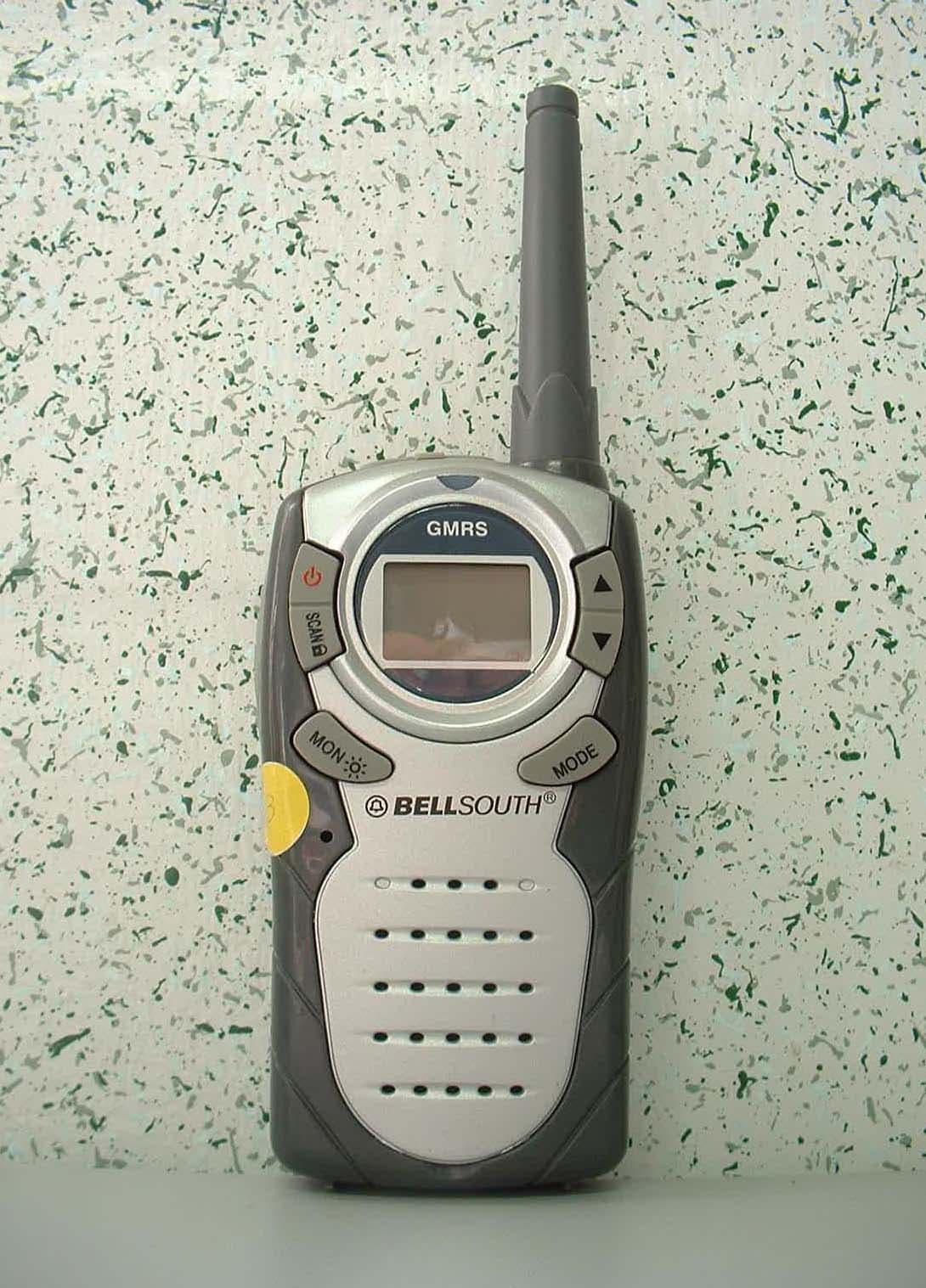
PM3GR5500
Jul 18, 2004GMRS/FRS UHF Transceiver
Equipment Class
FRF - Part 95 Family Radio Face Held Transmitter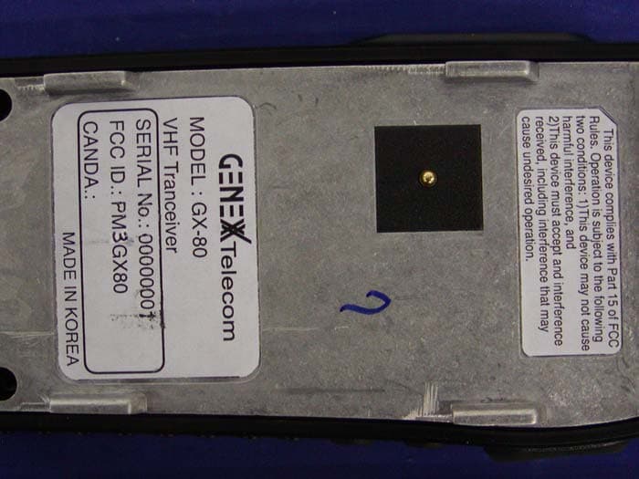
PM3GX80
Jul 01, 2004Transceiver, VHF, PTT
Equipment Class
TNF - Licensed Non-Broadcast Transmitter Held to Face
PM3GX90
Apr 05, 2004Transceiver, UHF, PTT
Equipment Class
TNF - Licensed Non-Broadcast Transmitter Held to Face