PM3GX80Transceiver, VHF, PTT
Genex Telecom Co., Ltd.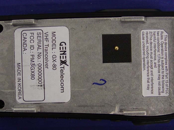
Click to zoom
Application Details
- Equipment Class
- TNF - Licensed Non-Broadcast Transmitter Held to Face
- Date of Grant
- Jul 01, 2004
- Application Purpose
- Original Equipment
- Date of Application
- Apr 08, 2004
- Equipment Note
- Transceiver, VHF, PTT
- Frequency Range
- 150.89750000 - 173.98750000
- Company
- Genex Telecom Co., Ltd.
- Country
- South Korea
Documents & Files
Document Text
Text extracted from the exhibit documents filed with the FCC. Open a document above to read the original.
Users Manual
GX-80/90 Genex Portable LMR radio FCC RF EXPOSURE COMPLIANCE REQUIREMENTS FOR OCCUPATIONAL USE ONLY The Federal Communications Commission (FCC), with its action in General Docket 93-62, November 7, 1997, has adopted a safety standard for human exposure to Radio Frequency (RF) electromagnetic energy emitted by FCC regulated equipment. Maxon subscribes to the same safety standard for the use of its products. Proper operation of this radio will result in user exposure far below the Occupational Safety and Health Act (OSHA) and Federal Communications Commission limits. DO NOT transmit for more than 50% of total radio use time (50% duty cycle). Transmitting more than 50% of the time can cause FCC RF exposure compliance requirements to be exceeded. •This radio is NOT approved for use by the general population in an uncontrolled environment. This radio is restricted to occupational use, work related operations only where radio operator must have the knowledge to control the user’s exposure conditions for satisfying the higher exposure limit allowed for occupational use. •When transmitting, hold the radio in a vertical position with its microphone 2 inches (5 cm) away from your mouth. The radio is transmitting when the red LED on the front of the radio is illuminated. You can cause the radio to transmit by pressing the PTT bar on the radio. These are required operating configurations for meeting FCC RF exposure compliance. Failure to observe these restrictions mean violation. This equipment complies with the FCC RF Exposure Limits for controlled environments. - Function description 1. power on& volume control (1) Power On Turn radio on by turning the power/volume Rotary switch clockwise out of detent. When radio turns on, it make beep sound. (2) Power Off Turning the power /volume rotary switch counterclockwise out of detent (3) Volume up/down Adjusting level of volume by turning Volume rotary switch. 2. Channel Selecting (Up/Down) User can choose a channel by adjusting Channel rotary switch 3. RX Operation 1) Busy condition is that unit is receiving a signal fixed in its channel Unit in the busy condition will be operated according to a fixed input of tone and two Tone. Unit out of busy condition will remain LED Off 2) Correct Call If a incoming signal has same tone as a fixed input of tone in selected channel, This signal is called “Correct Unit will open Audio with Green LED, If a incoming signal is not correct call, LED will be On in orange. 3) Monitor Operation Whenever Monitor button is pressed, Audio must be opened regardless of the condition of busy or correct call. - Monitor On : press Monitor button in left side of radio, Audio will be opened. If press Monitor button for five seconds, Monitor button will be locked and then a opened audio will be maintained, even though user release monitor button. If user release monitor button within five seconds, Monitor function will be Off and then Audio will be controlled by a incoming signal. To be out of Monitor condition, Just press monitor again. 4) Scan operation - Normal scan On : Press Sacn Button on the left side of radio for two seconds, User can initiate scan with beep sound. If no conversation is detected on any channel in the scan list, Radio will make Error beep sound, Once Scan starts, LED will flash in order of the following step repeatedly as below RED ==Î GREED ===Î Orange It indicates that Scan is on progress. To stop scanning, Press Scan button again for a two seconds, Radio will go back to the original channel used before start a scan and then radio stops flashing LED. If a conversation is detected a correct call, radio will stop on that channel and user will be able to hear the conversation. If programmed for normal scan TX, you will be able to transmit on that active channel during the programmable scan delay time. The scan delay time is the amount of time. Radio will stay on that channel once activity has cased. The radio will resume scanning once the scan delay time has expired. Scanning will continue until the channel is changed or press scan button again. - Scan channel Delete : To temporarily delete a channel from the scan list, simply press the scan button for a short time while stopped on the channel to be detected. This will remove that channel from the scan list until the channel is changed or the radio’s power is reset. When power is restored or the scan list channel position is again selected, the original dealer programmed scan list will be activated. - Priority Scan On : A single channel is programmed as the “ Priority” channel. The radio will constantly monitor this channel with flashing LED while scanning and when the radio has stopped on an active channel. If a call is detected on the “priority” channel, the radio will automatically move to, and remain on the “ Priority” channel as long as the priority conversation takes places. “priority” channel activity takes precedence over all other conversations. - Priority Scan Off : To be out of “Priority scan” Just change Channel. Radio will stop for a programmed delay time and start scanning on priority scan option activity channel. - Look back (Receiving correct call in Priority scan mode) Any channel, when not in the scan mode can be programmed to “look back” at the priority channel. This feature is ideal for those who do not need scan as defined above, but want to make sure that they never miss a call on the “priority” channel if another channel has been selected, the radio will periodically “look back” at the Priority channel. If activity is detected on the “priority” channel, the radio will move to that channel for as long as it remains active. - Priority Scan TX : If a coming signal is not correct call, allow transmission on the normal channel. If a coming signal is a correct call, allow transmission on the correct call channel. After finish transmission, resume scan after scan delay time. - Muti Scan : if press Scan key while Priority scan mode is On, Priority…
Text truncated - open the document above for the full version.
Users Manual
GX-80/90 Genex Portable LMR radio FCC RF EXPOSURE COMPLIANCE REQUIREMENTS FOR OCCUPATIONAL USE ONLY The Federal Communications Commission (FCC), with its action in General Docket 93-62, November 7, 1997, has adopted a safety standard for human exposure to Radio Frequency (RF) electromagnetic energy emitted by FCC regulated equipment. Maxon subscribes to the same safety standard for the use of its products. Proper operation of this radio will result in user exposure far below the Occupational Safety and Health Act (OSHA) and Federal Communications Commission limits. •This radio is NOT approved for use by the general population in an uncontrolled environment. This radio is restricted to occupational use, work related operations only where radio operator must have the knowledge to control the user’s exposure conditions for satisfying the higher exposure limit allowed for occupational use. •When transmitting, hold the radio in a vertical position with its microphone 2 inches (5 cm) away from your mouth. The radio is transmitting when the red LED on the front of the radio is illuminated. You can cause the radio to transmit by pressing the PTT bar on the radio or, if in VOX mode, by simply talking above the threshold level set during VOX programming. DO NOT transmit either in PTT or VOX mode for more than 50% of total radio use time (50% duty cycle). Transmitting more than 50% of the time can cause FCC RF exposure compliance requirements to be exceeded. These are required operating configurations for meeting FCC RF exposure compliance. Failure to observe these restrictions mean violation. This equipment complies with the FCC RF Exposure Limits for controlled environments. - Function description 1. power on& volume control (1) Power On Turn radio on by turning the power/volume Rotary switch clockwise out of detent. When radio turns on, it make beep sound. (2) Power Off Turning the power /volume rotary switch counterclockwise out of detent (3) Volume up/down Adjusting level of volume by turning Volume rotary switch. 2. Channel Selecting (Up/Down) User can choose a channel by adjusting Channel rotary switch 3. RX Operation 1) Busy condition is that unit is receiving a signal fixed in its channel Unit in the busy condition will be operated according to a fixed input of tone and two Tone. Unit out of busy condition will remain LED Off 2) Correct Call If a incoming signal has same tone as a fixed input of tone in selected channel, This signal is called “Correct Unit will open Audio with Green LED, If a incoming signal is not correct call, LED will be On in orange. 3) Monitor Operation Whenever Monitor button is pressed, Audio must be opened regardless of the condition of busy or correct call. - Monitor On : press Monitor button in left side of radio, Audio will be opened. If press Monitor button for five seconds, Monitor button will be locked and then a opened audio will be maintained, even though user release monitor button. If user release monitor button within five seconds, Monitor function will be Off and then Audio will be controlled by a incoming signal. To be out of Monitor condition, Just press monitor again. 4) Scan operation - Normal scan On : Press Sacn Button on the left side of radio for two seconds, User can initiate scan with beep sound. If no conversation is detected on any channel in the scan list, Radio will make Error beep sound, Once Scan starts, LED will flash in order of the following step repeatedly as below RED ==Î GREED ===Î Orange It indicates that Scan is on progress. To stop scanning, Press Scan button again for a two seconds, Radio will go back to the original channel used before start a scan and then radio stops flashing LED. If a conversation is detected a correct call, radio will stop on that channel and user will be able to hear the conversation. If programmed for normal scan TX, you will be able to transmit on that active channel during the programmable scan delay time. The scan delay time is the amount of time. Radio will stay on that channel once activity has cased. The radio will resume scanning once the scan delay time has expired. Scanning will continue until the channel is changed or press scan button again. - Scan channel Delete : To temporarily delete a channel from the scan list, simply press the scan button for a short time while stopped on the channel to be detected. This will remove that channel from the scan list until the channel is changed or the radio’s power is reset. When power is restored or the scan list channel position is again selected, the original dealer programmed scan list will be activated. - Priority Scan On : A single channel is programmed as the “ Priority” channel. The radio will constantly monitor this channel with flashing LED while scanning and when the radio has stopped on an active channel. If a call is detected on the “priority” channel, the radio will automatically move to, and remain on the “ Priority” channel as long as the priority conversation takes places. “priority” channel activity takes precedence over all other conversations. - Priority Scan Off : To be out of “Priority scan” Just change Channel. Radio will stop for a programmed delay time and start scanning on priority scan option activity channel. - Look back (Receiving correct call in Priority scan mode) Any channel, when not in the scan mode can be programmed to “look back” at the priority channel. This feature is ideal for those who do not need scan as defined above, but want to make sure that they never miss a call on the “priority” channel if another channel has been selected, the radio will periodically “look back” at the Priority channel. If activity is detected on the “priority” channel, the radio will move to that channel for as long as it remains active. - Priority Scan TX : If a coming signal is not correct call, allow transmission on the normal channel. If a coming signal is a correct call, allow transmission on the correct call channel. After finish tran…
Text truncated - open the document above for the full version.
Users Manual
PROGRAMMING MANUAL FOR THE GX Series Radios CONTENTS 1. Program Install 2. Construction of GX Series PC Program • Menu Bar, Tool Bar • Model Select • Data Frame Select • Port select • Program • Splash window 3. System Data Frame • Max Channel Number • Tx Delay • Vox Level Select • Scan • TOT (Time Out Timer) 4. Channel Data Frame • Rx Freq • R-Tone • 2Tone • BCL • BCLO • P-SC • SC • Tx Freq • T-Tone • PW • CS • Scr 5. Two Tone Data Frame • Super Group Tone • Group Tone • Individual tone 1. Program Install 1) Insert the Instruction CD into the CD-ROM drive. The following screen appears inserting the CD. <Click “Next” to Install Gx Radio programmer. < Picture 1-1 > 2) Select the following to Install. <Click “Install”> < Picture 1-2 > 3) If a “Replace file” message appears, click check box and click “Yes”. < Picture 1-3 > 4) Click OK button in condition of checked Run application check box . < Picture 1-4 > 5) Click Start button in windows, GX8090 automatically create in Program Menu . < Picture 1-5 > 2. Construction of GX Series PC Programmer ♦ Menu Bar, Tool Bar, Model Select, Frame Select, Port Select, Program Button ♦ System Data Frame ♦ Channel Data Frame ♦ Two Tone Data Frame 1) Menu Bar, Tool Bar : Processing file and Printing Function • It can be set up to initial value from selected all mode value. • It can be open data file ***.dat form. • Save data to ***.dat form. • Print data from indicated form. 2) Model Select : Function of selecting Model. 3) Data Frame Select : Function of selecting Data Frame. 4) Port Select : Function of selecting Pin Serial communication port. 5) Program : Function of reading data or programming in SET. 1. Read : Click READ button, it can be read the data from SET. Term: 1> SET is turn means that press Monitor key and Scan key simultaneously. And then LED lights of SET will be turned to orange color. 2> Programmer cable connect between PC and Set. 3> Press READ button. 4> Error message will show as it below either cable does not connect or does not set PC link mode. 5> When job is done, it shows as it below and disappear.. 2. Write : You can write the data when you click the button. Condition: 1> SET is turn means that press Monitor key and Scan key simultaneously. And then LED lights of SET will be turned to orange color. 2> Programmer cable connect between PC and Set. 3> Press WRITE button. 4> It will ask you a question as it below because exisitin data will be erase when you write the data set. 5> If you click “Yes”, write window will be start. 4> When write to set is done, it will show window as it below. 6) Splash Window : It shows PC program information. ♦ System Data Frame 1) Max Channel Number 2) Tx Delay : End of TX, it protect squelch tail which come out turn off Tone or Code. 3) Vox Level Select : You can select voice function(on/off) for hands free and level. (Default Level : 2) 4) Scan : Automatic scan receiving channel. • Scan Enable : Scan Enable/Disable • Scan Speed : Delay time for No busy channel. Setting 10msec between 50msec ~ 500msec. (Default : 100 msec) • Scan Delay : Delay time of Busy channel. You can set 1sec delay between 1sec to 30sec. (Default : 5sec) • Priority Scan Enable : Priority Scan Enable/Disable • Prio. Scan Ch. No. : Priority Channel • Look Back time : Interval time for checking Priority channel when Non Priority Channel is busy. (0.5sec ~ 10sec : Default 4sec) 5) Power Save : If there is no signal comes in stand by mode, it goes power saving mode which set PC program. • Power Save Enable : Power Save Enable/Disable • Save On time : Power Save On Time You can set 0.1sec delay between 0.2sec~2sec. (Default : 0.2sec) • Save Off Time : Power Save Off Time You can set 0.1sec delay between 0.2sec~2sec. (Default : 0.2sec) • Save Delay time : Need time from normal mode to power save mode. You can set 0.5sec delay between 0.5sec~10sec. (Default : 5sec) 6) TOT ( Time Out Timer) • TOT Enable : TOT function (On/Off) • TX Time-Out time : Set between 10sec to 990sec. • TOT Penalty Enable : When TX, if TOT time is exceed, it prohibit(stop) to TX within penalty time.(on/off) Set between 1sec to 100sec. ♦ Channel Data Frame 1) Rx Freq : It can be select receiving frequency. • When you double click or press enter key, it can be state of insert as follows. • I f you click other cell and press return key or navigation key with mouse, it automatically check and input data. 2) R-Tone : It is selected CTCSS , DCS, IDCS Tone in state of receiving. • When you double click or press enter key, it comes tone selecting window as follows . • When you double click or press enter which tone you want, it comes to select each window. • In each window, when you double click or press return key of sudden code, selected code shows at the cell. <Select CTCSS Tone> <Select DCS Tone> <Select IDCS Tone> 3) 2Tone : Selecting Two Tone • W hen you double click or press enter key, it comes two tone window. • It is indicated on Cell, when you check tone which you choose, it shows selected tone. • It can be closed to click button. 4) BCL : It is the option for inhibit transmit when occupied channel is busy. • It can be select to double click or press enter key. The state of On is indicated yellow color. 5) BCLO : It is • It can be On in BCL On. • Correct call staus : staus that possible to listen signal after opening audio port which matching actual signal and RX data which set each channel. There are CTCSS, DCS, IDCS, and two tone in RX data. 6) P-SC : Priority Scan function On/Off. 7) SC : Scan function On/Off. 8) Tx Freq : Insert transmit frequency. It is same of method of receive frequency. 9) T-Tone : It can be set transmission tone. . 10) PW : It can be set power of transmitter. (H : high power , L : low power) 11) CS : It can be set Channel space. ( N/S band control ) 12) Scr : It can be set Scrambler Option. • when you double click or press enter key, it comes scramble channel window. • when you choose scramble channel, it shows chose channel at the cel…
Text truncated - open the document above for the full version.
Cover Letter(s)
Bay Area Compliance Laboratory Corp. 230 Commercial Street Sunnyvale, CA 94085 Tel: (408) 732-9162 Fax: (408) 732-9164 www.baclcorp.com 2004-06-15 Applicant: Genex Telecom Co., Ltd. FCC ID: PM3GX80 Correspondence Reference Number: 26809 731 Confirmation Number: EA778782 Date of Original E-Mail: 5/13/2004 Subject: FCC Equipment Authorization System 1) Please justify that phantom meets Supplement C recommendations of twice the device size in length and width. Answer: Please see the new test setup photos in updated SAR report page 50 and the flat phantom dimension on page 47. 2) Please provide SAR contour plots covering the entire device and antenna. Answer: Please see the new plots for test results in updated SAR report page 48-49. 3) Please update the user manual statements to include instructions for assuring 50 % duty factor for VOX operation. Answer: Please see the updated users manual page 1 and the programming manual. 4) The FCC believes the SAR tests performed contain factors that significantly increase measurement uncertainty. The large power droop in the device under test produces a dynamic SAR distribution. The SAR measurement system used appears to assume a constant distribution. To determine if the SAR values provided are conservative please perform two additional tests 1) a SAR test using an external power supply to supplement the batteries. Please use shielding and ferrite current dampeners on any wires used. 2) A test starting after the output power has stabilized, the SAR value should than be scaled up to full power. Tests in the worst case configuration for both head and body is considered sufficient. Answer: We are now using DC power supply to do the testing. Please refer to the new SAR report page 47-50. 5) Please show calculations of the necessary bandwidth per Section 2.202 of the FCC rules. Answer: Please see formula on the new FCC test report page 16 for the calculations of the bandwidth. Jennifer Song Document Control Bay Area Compliance Lab. Corp. Tel: 408-732-9162 x39
External Photos
GENEX Telecom CO., LTD. FCC ID: PM3GX80 APPENDIX C - EUT PHOTOGRAPHS Chassis - Front View Chassis – Back View I GENEX Telecom CO., LTD. FCC ID: PM3GX80 Chassis – Back View II Chassis – Back Frame GENEX Telecom CO., LTD. FCC ID: PM3GX80 Chassis – Top View GENEX Telecom CO., LTD. FCC ID: PM3GX80 Chassis – Left Side View Chassis – Right Side View GENEX Telecom CO., LTD. FCC ID: PM3GX80 Adapter View Battery Charger – Front View GENEX Telecom CO., LTD. FCC ID: PM3GX80 Battery Charger – Rear View
ID Label/Location Info
APPENDIX A - FCC ID LABELING AND LOCATION Proposed FCC ID Labeling Proposed FCC ID Location Rear Side of EUT / Proposed Label Location FCC ID: PM3GX80
Internal Photos
GENEX Telecom CO., LTD. FCC ID: PM3GX80 Battery Charger – Cover off View GENEX Telecom CO., LTD. FCC ID: PM3GX80 Battery Charger – Component View Battery Charger – Solder View GENEX Telecom CO., LTD. FCC ID: PM3GX80 PCB – Top View PCB – Bottom View
Operational Description
THEORY OF OPERATION Theory of Operation on GX Series The GX Series Handheld Radio Transceivers are comprised of one main PCB. The main PCB contains the transmitter, receiver, and control circuits. Receiver The receiver circuit adopts dual conversion super heterodyne with 1 st IF 45.1MHz and 2 nd IF 455kHz Front-end Front-end consists of pre-selector filter, RF Amplifier, Post-selector filter. The receive signal is routed through C3 and selected by C4, C6, L2, L3 to amplified around 13dB at RF amp. Q19. Front-end adjusts bandwidth by varicap diode tuning. This circuit removes unnecessarily spurious 1st Image. First Mixer The signal from Front-end is input to Q18 base of 1 st mixer. 1 st local signal generated from VCO is input to Q18, emitter. These two signals are mixed at Mixer into 1 st IF signal 45.1MHz, which is resonated in parallel at C22, L8 and inputted to XF1, Pair crystal filter. IF Amplifier 1 st IF signal from XF1 is amplified about 15dB at IF amp Q17 and inputted to IC3, IF IC. 2 nd Local Oscillator is 44.645MHz. The signal from 2 nd Mixer is refined removing unnecessary spurious signal and detected through high gain linear amp. This detected signal is inputted to IC3 pin9. AF Amplifier 300Hz High Pass Filter IC507 removes the signal under 300Hz of the demodulated signal from IC3 so that noise under sub tone use is removed. De-emphasis functions to get 6dB/oct by R601, C533 and this signal controls volume of sound by RV502. IC508 can operate a speaker as audio current amplifier amplifying the signal. The operating current can be reduced by mute signal. Squelch The demodulated signal from IC3 is coupled of noise to C35. The noise is filtered and amplified by C45,109, R30 and used internal amplifier of IC3. This noise signal is used as the signal to mute RV2 audio. Audio AMP After CTCSS,DCS signal is removed at 300Hz High Pass Filter and de-emphasized to – 6 dB/Oct at R601, C533 the volume of sound is controlled by RV502. IC508 is doing low frequency current amplify as audio amplifier to operate a speaker. IC508 has mute function and if Pin 2, mute port is high, it's on mute. If it is low, it's unmuted. Transmitter The transmitter consists of Buffer, Power Amplifier, Low-Pass Filter, Antenna Switch, Auto-Power Control. 2-1) Buffer -6dBm TX RF signal from VCO is amplified to around +29dBm by buffer Q22,26 to have desired output power at final Amp. Pie style resister attenuator is used between VCO and Buffer Amp. To minimize the effect of load caused by transmit amplifier in TX. 2-2) Power Amplifier TX RF Signal form buffer Amp. Gains 6Watt output by final Amp Q27. Collect impedance of Q27 states in low so that it is matching to 50ohm by C97, 98, 99, 100, strip line and inputted to 5 th Low Pass Filter. 2-3) Low Pass Filter 5 th Low Pass Filter reduces the unwanted spurious for TX output power from final Amp. L19, 20, C103, 104, 105, 106, 107 are Chebisheve Filter. 2-4) Antenna Switch Ant. Switch is to share the antenna in TX and RX. It prevents TX sensitivity from degradation by LPF. Also, it protects receive circuit by blocking TX signal to receive end, turning on D1, 2. Flow of the signal in RX is designed to minimize the loss of the signal using the character of series resonance of L1, C3. 2-5) Auto-Power Control This circuit controls TX Power by detection on the current through R95. The voltage difference from these resistors is amplified by IC4-B and gets the voltage comparing the this signal with the reference voltage from R84, 85 at IC4-A. This voltage difference is kept to stable value by RV4 changing Gate voltage of Final Amp. PLL Synthesizer Reference frequency is 12.8MHz and this oscillated frequency is compensated in temperature. The frequency from VCO is inputted to PLL IC and this inputted signal is divided by the ratio set by data and compared with reference step frequency. Then, the difference comes to IC1 pin15,16 Port. GX series consists of external charge pump. Charge pump output turns into DC by PLL LPF R56, 57, 58, C59, 60, 61, 62 so that it can vary VCO control voltage to have set frequency. For TX and RX switch, Q305 and Q3304 base switch to control voltage.(TX_EN) Audio and Control circuit IC501 controls all factions of the radio as Microprocessor. It detects outer condition such as function data on frequency, Power supply switching and make it operate correctly. IC509 consists of 250Hz LPF to function CTCSS,DCS decoding correctly and he output of this filter is amplified at IC509- A. Then, it goes to Q503 to be changed to logic signal so that CTCSS,DCS decoding is enabled. IC509-A is CTCSS,DCS Encode Filter. It mixes the signals from 4 ports and this mixed signal goes through this filter to get clear CTCSS,DCS signal. IC509-B, C, and D is TX Audio Amp and limiter. It amplifies the voice signal from C-Mic and have the character of 6dB/Oct Pre-Emphasis. This voice signal is controlled by RV501 for the volume. IC509-B is 3KHz LPF and has the character that reduces to 18dB/Oct. This character minimizes the interference of adjacent channel by voice signal. Alignment Procedure This radio is adjusted to meet all condition in production except special case. Readjustment is not requirement. 5-1) The preparation before adjustment. 1) Set the Power Supply voltage to 7.4V and then connect to the radio. 2) Connect the connector to Radio Antenna terminal. 3) Connect the radio to test equipment. 5-2) PLL Synthesizer 1) Measure the voltage of TP1 with High impedance voltage meter. 2) Adjust TC301 at RX channel 1.0 to be 1.5V. Confirm if it is below 13V at RX high channel. Adjust TC302 at TX channel 1.0 to be 1.5V. Confirm if it is below 13V at TX high channel. 3) Confirm if Channel 1 is in 1.0 +/-0.3 in TX. 5-3) Adjustment of Transmitter 1) Adjust to tune the set frequency. 2) Adjust RV4 to tune the set power. 3) Set Audio Generator to be 1kHz 120mVrms and connect to Radio External Jack. 4) Adjust RV501 to tune desired modulation. 5) If a channel is set with CTCSS,DCS …
Text truncated - open the document above for the full version.
Parts List/Tune Up Info
GX-80 / GX-90 Alignment The GX-80/90 has been carefully aligned at the factory for the specified performance across the frequency range specified for each version. Re-alignment should therefore not be necessary except in the event of component failure, or altering version type. All component replacement and service should only be performed by an authorized GENEX TELECOM representative, or the warranty policy may be void. Required Test Equipment z RF Signal Generator with calibrated output level at 1 GHz(or RADIO COMMUNITION TEST SET) z Deviation Meter (Liner Detector) z AC Voltmeter z SINAD Meter z In-Line Wattmeter with 5% accuracy at 500 MHz z Regulated DC Power Supply adjustable from 4 to 10V, 3A z 50Ω Non-reactive Dummy Load: 10W at 500MHz z Frequency Counter: ±0.2 ppm accuracy at 500MHz z AF Signal Generator z DC Voltmeter: High impedance GX-80 Low Band Edge (Channel 1): 136.000MHz Band Center (Channel 2): 155.000MHz High Band Edge (Channel 3): 174.000MHz GX-90 Low Band Edge (Channel 1): 430.000MHz Band Center (Channel 2): 450.000MHz High Band Edge (Channel 3): 470.000MHz Note: Signal levels in dB referred in the alignment procedure are based on 0 dBμ = 0.5 . PLL & Transmitter Set up the test equipment as shown for transmitter alignment. Adjust the supply voltage to 7.4V for all steps where not specified otherwise. PLL VCV (Varactor Control Voltage) z Connect the DC voltmeter between TP1 on the Main Unit and Ground. z Set the transceiver to CH1 (low band edge), and adjust TC301 on the Main Unit for 1.0V ± 0.1V on the DC voltmeter, while receiving. z Set the transceiver to CH1 (low band edge), and adjust TC302 on the Main Unit for 1.0V ± 0,1V on the DC Voltmeter, while transmitting. z Set the transceiver to CH3 (high band edge), and confirm the high-end VCV is lower then 12.0V while receiving, and low than 12.0V while transmitting. PLL Reference z Set the transceiver to CH1 (low band edge), and adjust trimmer of the VCXO on the Main Unit for band center frequency ±100Hz . Transmitter Output Power z Set the transceiver to CH1 (low band edge), and adjust RV2 on the Main Unit for that the power meter reading is 5W. Confirm that the current consumption is 2.0A or below. z Set the transceiver to CH1 (low band edge), and adjust RV3 on the Main Unit for that the power meter reading is 1W. Confirm that the current consumption is 1.0A or below. Modulation Level Max Deviation: (VCO Modulation) z Set the transceiver to CH2 (band center). z Inject a 1KHz tone at 100mVrms to the MIC jack. z Adjust RV501 on the Main Unit for the deviation meter reading is ±4.2KHz(for 25KHz steps) or ±2.1KHz(for 12.5KHz steps) deviation. MIC Sensitivity z Set the transceiver to CH2 (band center) z Inject a 1KHz tone at 100mVrms to the MIC jack. z Adjust tone level so that the deviation meter reading is ±3.0KHz (for 25KHz steps) or ± 1.5KHz (for 12.5KHz steps) deviation. CTCSS Deviation z Set the transceiver to CH2 (band center). z Check the deviation meter reading is ±0.7KHz (for 25KHz steps) or ±0.35KHz (for 12.5KHz steps) deviation. CDCSS Deviation z …
Text truncated - open the document above for the full version.
Contact Information
Applicant
Clark Cheon(Manager)
Test Firm
Bay Area Compliance Laboratory Corp.John Chan
Technical Specifications
| # | Rule Parts | Frequency Range | Power Output | Emission | Tolerance |
|---|---|---|---|---|---|
| 1 | 90 | 150.8975 MHz - 173.9875 MHz | 4.819 W | 14K0F3E | 2.5000000000 ppm |
Other Applications from Genex Telecom Co., Ltd.

PM3GT40
Dec 08, 2004UHF LMRS TRANSMITTER
Equipment Class
TNF - Licensed Non-Broadcast Transmitter Held to Face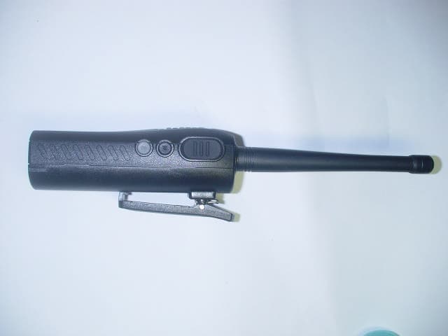
PM3GT10
Dec 08, 2004UHF LMRS TRANSMITTER
Equipment Class
TNF - Licensed Non-Broadcast Transmitter Held to Face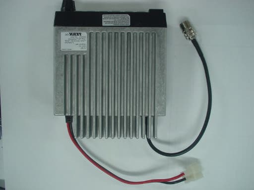
PM3MT900
Nov 28, 2004LAND MOBILE RADIO SERVICE GMRS TRANSMITTER
Equipment Class
TNB - Licensed Non-Broadcast Station Transmitter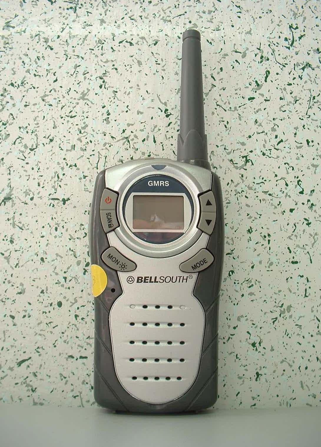
PM3GR5500
Jul 18, 2004GMRS/FRS UHF Transceiver
Equipment Class
FRF - Part 95 Family Radio Face Held Transmitter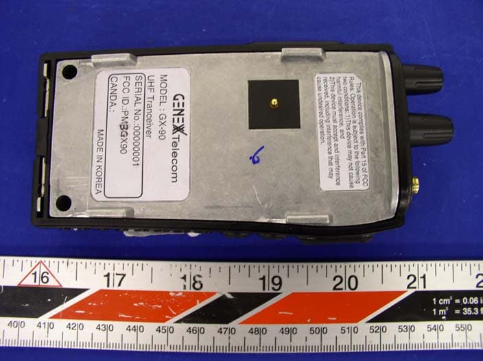
PM3GX90
Apr 05, 2004Transceiver, UHF, PTT
Equipment Class
TNF - Licensed Non-Broadcast Transmitter Held to Face