PM3GBH-200HBluetooth Headset
Genex Telecom Co., Ltd.
Click to zoom
Application Details
- Equipment Class
- DSS - Part 15 Spread Spectrum Transmitter
- Date of Grant
- Jan 21, 2003
- Application Purpose
- Original Equipment
- Date of Application
- Jan 21, 2003
- Equipment Note
- Bluetooth Headset
- Frequency Range
- 2402.00000000 - 2480.00000000
- Company
- Genex Telecom Co., Ltd.
- Country
- South Korea
Documents & Files
Document Text
Text extracted from the exhibit documents filed with the FCC. Open a document above to read the original.
External Photos
CETECOM ICT Services GmbH Test Report No.: 2-3103-01-05-B/02Issue Date: 2002-12-19Page 62 (67) Photographs of the equipment CETECOM ICT Services GmbH Test Report No.: 2-3103-01-05-B/02Issue Date: 2002-12-19Page 63 (67) Photographs of the equipment CETECOM ICT Services GmbH Test Report No.: 2-3103-01-05-B/02Issue Date: 2002-12-19Page 67 (67) Photographs of the equipment
ID Label/Location Info
GBH -200H (Headset) - Actual Size - - Scale 500% -
Internal Photos
CETECOM ICT Services GmbH Test Report No.: 2-3103-01-05-B/02Issue Date: 2002-12-19Page 64 (67) Photographs of the equipment CETECOM ICT Services GmbH Test Report No.: 2-3103-01-05-B/02Issue Date: 2002-12-19Page 65 (67) Photographs of the equipment CETECOM ICT Services GmbH Test Report No.: 2-3103-01-05-B/02Issue Date: 2002-12-19Page 66 (67) Photographs of the equipment
Operational Description
1 Appendix A BLUETOOTH APPROVALS The following exhibit indicates the FCC Spread Spectrum requirements in Section 15.247 for devices meeting the Bluetooth Specifications in the 2.4 GHz band as of February 2001 operating in the USA. The purpose of this exhibit is to help expedite the approval process for Bluetooth devices. This exhibit provides items that vary for each device and also provides a list of items that are common to Bluetooth devices that explains the remaining requirements. The list of common items can be submitted for each application for equipment authorization. This exhibit only specifies requirements in Section 15.247, requirements in other rule Sections for intentional radiators such as in Section 15.203 or 15.207 must be also be addressed. A Bluetooth device is a FHSS transmitter in the data mode and applies as a Hybrid spread spectrum device in the acquisition mode. For each individual device, the following items, 1-7 will vary from one device to another and must be submitted. 1) The occupied bandwidth in Section 15.247(a)(1)(ii). 2) Conducted output power specified in Section 15.247(b)(1). 3) EIRP limit in Section 15.247(b)(3). 4) RF safety requirement in Section 15.247(b)(4) 5) Spurious emission limits in Section 15.247(c). 6) Processing gain and requirements for Hybrids in Section 15.247(f) in the acquisition mode. 7) Power spectral density requirement in Section 15.247(f) in the acquisition mode. For all devices, the following items, 1-12, are common to all Bluetooth devices and will not vary from one device to another. This list can be copied into the filing. 1 Output power and channel separation of a Bluetooth device in the different operating modes: The different operating modes (data-mode, acquisition-mode) of a Bluetooth device don’t influence the output power and the channel spacing. There is only one transmitter which is driven by identical input parameters concerning these two parameters. Only a different hopping sequence will be used. For this reason, the RF parameters in one op-mode is sufficient. 2 Frequency range of a Bluetooth device: The maximum frequency of the device is: 2402 – 2480 MHz. This is according the Bluetooth Core Specification V 1.0B (+ critical errata) for devices which will be operated in the USA. Other frequency ranges ( e.g. for Spain, France, Japan) which are allowed according the Core Specification must not be supported by the device. 3 Co-ordination of the hopping sequence in data mode to avoid simultaneous occupancy by multiple transmitters: Bluetooth units which want to communicate with other units must be organized in a structure called piconet. This piconet consist of max. 8 Bluetooth units. One unit is the master the other seven are the slaves. The master co-ordinates frequency occupation in this piconet for all units. As the master hop sequence is derived from it’s BD address which is unique for every Bluetooth device, additional masters intending to establish new piconets will always use different hop sequences. 2 4 Example of a hopping sequence in data mode: Example of a 79 hopping sequence in data mode: 40, 21, 44, 23, 42, 53, 46, 55, 48, 33, 52, 35, 50, 65, 54, 67, 56, 37, 60, 39, 58, 69, 62, 71, 64, 25, 68, 27, 66, 57, 70, 59, 72, 29, 76, 31, 74, 61, 78, 63, 01, 41, 05, 43, 03, 73, 07, 75, 09, 45, 13, 47, 11, 77, 15, 00, 64, 49, 66, 53, 68, 02, 70, 06, 01, 51, 03, 55, 05, 04 5 Equally average use of frequencies in data mode and short transmissions: The generation of the hopping sequence in connection mode depends essentially on two input values: 1. LAP/UAP of the master of the connection 2. Internal master clock The LAP (lower address part) are the 24 LSB’s of the 48 BD_ADDRESS. The BD_ADDRESS is an unambiguous number of every Bluetooth unit. The UAP (upper address part) are the 24 MSB’s of the 48 BD_ADDRESS. The internal clock of a Bluetooth unit is derived from a free running clock which is never adjusted and is never turned off. For synchronization with other units, only the offsets are used. It has no relation to the time of the day. Its resolution is at least half the RX/TX slot length of 312.5 μs. The clock has a cycle of about one day (23h30). In most case it is implemented as 28 bit counter. For the deriving of the hopping sequence the entire LAP (24 bits), 4 LSB’s (4 bits) (Input 1) and the 27 MSB’s of the clock (Input 2) are used. With this input values different mathematical procedures (permutations, additions, XOR-operations) are performed to generate the sequence. This will be done at the beginning of every new transmission. Regarding short transmissions, the Bluetooth system has the following behavior: The first connection between the two devices is established, a hopping sequence is generated. For transmitting the wanted data, the complete hopping sequence is not used and the connection ends. The second connection will be established. A new hopping sequence is generated. Due to the fact that the Bluetooth clock has a different value, because the period between the two transmission is longer (and it cannot be shorter) than the minimum resolution of the clock (312.5 μs). The hopping sequence will always differ from the first one. 6 Receiver input bandwidth, synchronization and repeated single or multiple packets: The input bandwidth of the receiver is 1 MHz. In every connection, one Bluetooth device is the master and the other one is the slave. The master determines the hopping sequence (see chapter 5). The slave follows this sequence. Both devices shift between RX and TX time slot according to the clock of the master. Additionally the type of connection (e.g. single or multi-slot packet) is set up at the beginning of the connection. The master adapts its hopping frequency and its TX/RX timing is according to the packet type of the connection. Also, the slave of the connection uses these settings. Repeating of a packet has no influence on the hopping sequence. The hopping sequence generated by the master of t…
Text truncated - open the document above for the full version.
Operational Description
Operation Manual - System Overview - Components - General RF Spec. <System overview> The products have been developed for bluetooth headset service to customers. They consists of Headset(H/S), Audiogate(A/G). <Components> H/S components are : u main basic module u I/F module u Battery u Speaker u Microphone A/G components are : u same main basic module u I/F module u Battery u audio-jack cord. Technical Circuit Description 1. Main Basic Module - common U4(BC02-External) Bluecore2-External is a single chip radio and baseband IC for Bluetooth 2.4GHz system. U3(Flash-SST39VF800-90-4C-B3K) Flash memory is loaded Bluetooth stack firmare which runs on the internal RISC microcontroller. This is compliant with the Bluetooth specification. U1(X’tal-TSX-3225) X’tal is supplied with reference clock. The clock frequency is 16 MHz. U2(Balun) The balun device is converted the differential RF signal to single RF signal. F1(Band pass filter-BPF) The BPF filters RF signal. The bandwidth of the BPF is 2.4GHz~2.483GHz. The insertion loss is 0.3 dB. 2. I/F Module of H/S U233(CODEC-MC145483) CODEC is supplied with PCM_OUT, PCM_IN, PCM_CLK, PCM_SYNC from U4. This signals carry up to bi-directional channels of voice data, each at 8ksamples/s. The format of the PCM samples can be 8-bit u-law, 13 bit linear or 16- bit linear. U165/U166(Voltage Regulator-R1140Q) The output voltage of these regulators is internally fixed high accuracy. The voltage is 3.0 Volt. 3. I/F Module of A/G U1(Optocoupler-TCMT11_4P) Optocoupler is used by the purpose of input and output isolation. The element are mounted on one leadframe using a coplanar technique, providing a fixed distance between input and output for highest safety requirements. <General RF Spec.> ITEMSSPECIFICATIONREMARK Frequency Range2400 MHz ~ 2483.5 MHzISM Band Maximum Output Power3 dBmCLASS II Minimum Output Power-14 dBmCLASS II Spurious EmissionsUnder -30 dBm2483.5 MHz < f < 2400 MHz SensitivityUnder -81 dBmBER ≤ 0.1 %
Test Report
CETECOM ICT Services GmbH Radio Satellite Communication Untertürkheimer Straße 6-10 . D-66117 SaarbrückenTelephon: +49 (0)681 598-0Telefax: -9075 RSC14issue test report consist of 67 PagesPage 1 (67) Recognized by the Federal Communications Commission FCC–Identification Number: 90462 TCB ID: DE 001 Accredited by the German Accreditation Council DAR–Registration Number TTI–P–G 166/98 Independent ETSI compliance test house ETSI Accredited Bluetooth™ Test Facility (BQTF) Test Report No.: 2-3103-01-05-B/02 FCC Part 15.247 / CANADA RSS-210 Bluetooth Headset GBH-200H FCC ID: PM3GBH-200H CETECOM – ICT Services GmbH Untertürkheimerstr. 6-10 66117 Saarbrücken, Germany Telephone: + 49 (0) 681 / 598-0 Fax: + 49 (0) 681 / 9075 BLUETOOTH is a trademark owned by Bluetooth SIG, Inc. and licensed to CETECOM CETECOM ICT Services GmbH Test Report No.: 2-3103-01-05-B/02Issue Date: 2002-12-19 Page 2 (67) Table of Contents 1 General Information 1.1 Notes 1.2 Testing Laboratory 1.3 Details of Applicant 1.4 Application Details 1.5 Test Item 1.6 Test Specifications 2 Technical Test 2.1 Summary of Test Results 2.2 Test Report CETECOM ICT Services GmbH Test Report No.: 2-3103-01-05-B/02Issue Date: 2002-12-19 Page 3 (67) 1 General Information 1.1 Notes The test results of this test report relate exclusively to the test item specified in 1.5. The CETECOM ICT Services GmbH does not assume responsibility for any conclusions and generalisations drawn from the test results with regard to other specimens or samples of the type of the equipment represented by the test item. The test report may only be reproduced or published in full. Reproduction or publication of extracts from the report requires the prior written approval of the CETECOM ICT Services GmbH. Test Laboratory Manager: 2003-01-07RSC8411Berg M. DateSectionNameSignature Technical Responsibility for Area of Testing: 2003-01-07RSC8412Hausknecht D. DateSectionNameSignature CETECOM ICT Services GmbH Test Report No.: 2-3103-01-05-B/02Issue Date: 2002-12-19 Page 4 (67) 1.2 Testing Laboratory CETECOM ICT Services GmbH Untertürkheimer Straße 6 - 10 66117 Saarbrücken Germany Telephone: + 49 681 598 - 0 Telefax : + 49 681 598 - 9075 E-mail : [email protected] Internet : www.cetecom-ict.de Accredited testing laboratory The Test laboratory (area of testing) is accredited according to DIN EN ISO/IEC 17025. DAR-registration number : TTI-P-G 166/98-30 Accredited Bluetooth™ Test Facility (BQTF) BLUETOOTH is a trademark owned by Bluetooth SIG, Inc. and licensed to CETECOM 1.3Details of Applicant Name : Genex Telecom Co., Ltd.. Street : 796-27 BangBae-Dong, Seocho-Gu City : Seoul Country : Korea 137-830 Telephone : +82-2-803-9002 Telefax : +82-2-591-1801 Contact : Mr. Jackey Jeong Telephone : +82-2-803-9002 #160 1.3 Application Details Date of receipt of application : 2002-11-28 Date of receipt of test item : 2002-12-16 Date of test : 2002-12-16/19 CETECOM ICT Services GmbH Test Report No.: 2-3103-01-05-B/02Issue Date: 2002-12-19 Page 5 (67) 1.4 Test Item Type of equipment : Bluetooth ™ Headset Type designation: GBH-200H Manufacturer: Genex Telecom Co., Ltd.. Street: 6Fl Farmax Sports Plaza Bldg. 796-27 BangBae-Dong, Seocho-Gu City: Seoul Country: Korea 137-830 Serial number: -.- FCC ID: PM3GBH-200H Hardware: V1.0 Software : V1.0 Additional information : Frequency: 2402 – 2480 MHz Type of modulation: 1M00FXD / 79M8FXD (FHSS) Number of channels : 79 Antenna: Chip Antenna 0,0 dBi Power supply: Li-Ion battery 3.7V Output power: EIRP: 0.752 mW (worst case) Temperature range: -10°C - +40°C 1.5 Test Specifications: FCC Part 15 §15.247 CANADA RSS-210 CETECOM ICT Services GmbH Test Report No.: 2-3103-01-05-B/02Issue Date: 2002-12-19 Page 6 (67) 2 Technical Test 2.1Summary of Test Results The radiated measurements are performed in vertical and horizontal plane in the frequency range from 9 kHz to 25 GHz in semi-anechoic chambers. The EUT is positioned on a non- conductive support with a height of 0.80 m above a conductive ground plane that covers the whole chamber. The receiving antennas are conform with specifications ANSI C63.2-1987 clause 15 and ANSI C63.4-1992 clause 4.1.5. These antennas can be moved over the height range between 1.0 m and 4.0 m in order to search for maximum field strength emitted from EUT. The measurement distances between EUT and receiving antennas are indicated in the test setups for the various frequency ranges. For each measurement, the EUT is rotated in all three axes until the maximum field strength is received. The wanted and unwanted emissions are received by spectrum analysers where the detector modes and resolution bandwidths over various frequency ranges are set according to requirement ANSI C63-4-1992 clause 4.2. Antennas are conform with ANSI C63.2-1996 item 15. 150 kHz - 30 MHz: Quasi Peak measurement, 9kHz Bandwidth, passive loop antenna. 30 MHz - 200 MHz: Quasi Peak measurement, 120KHz Bandwidth, biconical antenna 200MHz - 1GHz: Quasi Peak measurement, 120KHz Bandwidth, log periodic antenna 1GHz: Average, RBW 1MHz, VBW 10 MHz, waveguide horn The product fullfills also the requirements for CANADA RSS-210 No deviations from the technical specification(s) were ascertained in the course of the tests performed. Final verdict : PASS Remark : CETECOM ICT Services GmbH Test Report No.: 2-3103-01-05-B/02Issue Date: 2002-12-19 Page 7 (67) 2.2Test Report TEST REPORT Test Report No. : 2-3103-01-05-B/02 CETECOM ICT Services GmbH Test Report No.: 2-3103-01-05-B/02Issue Date: 2002-12-19 Page 8 (67) TEST REPORT REFERENCE LIST OF MEASUREMENTS ParagraphPARAMETER TO BE MEASUREDPAGE Transmitter parameters Antenna gain 9 § 15.247 (a)(1) Carrier frequency separation10 § 15.247 (a)(1)Number of hopping channels11 § 15.247 (a)(1 iii) Time of occupancy (dwell time)13 § 15.247 (d) Power spectral density (Inquiry/Page mode)18 § 15.247 (a)(1)Spectrum bandwidth of a FHSS System19 § 15.247 (b)(2)Maximum peak output power23 §15.247 (c)Band edge compliance 28 § 15.247 (c)Emissi…
Text truncated - open the document above for the full version.
Test Setup Photos
CETECOM ICT Services GmbH Test Report No.: 2-3103-01-05-B/02Issue Date: 2002-12-19Page 58 (67) Test setup CETECOM ICT Services GmbH Test Report No.: 2-3103-01-05-B/02Issue Date: 2002-12-19Page 59 (67) Test setup CETECOM ICT Services GmbH Test Report No.: 2-3103-01-05-B/02Issue Date: 2002-12-19Page 60 (67) Test setup CETECOM ICT Services GmbH Test Report No.: 2-3103-01-05-B/02Issue Date: 2002-12-19Page 61 (67) Test setup
Contact Information
Applicant
Clark Cheon(Manager)
Test Firm
Cetecom ICT Services GmbHRalf Hoehn
Technical Specifications
| # | Rule Parts | Frequency Range | Power Output |
|---|---|---|---|
| 1 | 15C | 2.40 GHz - 2.48 GHz | 800.00 µW |
Other Applications from Genex Telecom Co., Ltd.
PM3GT40
Dec 08, 2004UHF LMRS TRANSMITTER
Equipment Class
TNF - Licensed Non-Broadcast Transmitter Held to Face
PM3GT10
Dec 08, 2004UHF LMRS TRANSMITTER
Equipment Class
TNF - Licensed Non-Broadcast Transmitter Held to Face
PM3MT900
Nov 28, 2004LAND MOBILE RADIO SERVICE GMRS TRANSMITTER
Equipment Class
TNB - Licensed Non-Broadcast Station Transmitter
PM3GR5500
Jul 18, 2004GMRS/FRS UHF Transceiver
Equipment Class
FRF - Part 95 Family Radio Face Held Transmitter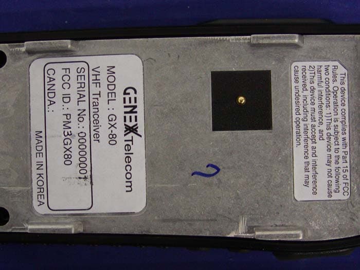
PM3GX80
Jul 01, 2004Transceiver, VHF, PTT
Equipment Class
TNF - Licensed Non-Broadcast Transmitter Held to Face