PM3GM22GMRS UHF Transceiver
Genex Telecom Co., Ltd.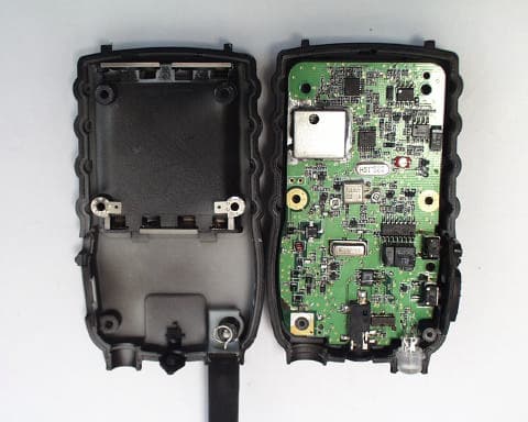
Click to zoom
Application Details
- Equipment Class
- TNF - Licensed Non-Broadcast Transmitter Held to Face
- Date of Grant
- Oct 24, 2002
- Application Purpose
- Original Equipment
- Date of Application
- Oct 24, 2002
- Equipment Note
- GMRS UHF Transceiver
- Frequency Range
- 467.55000000 - 467.72500000
- Company
- Genex Telecom Co., Ltd.
- Country
- South Korea
Documents & Files
Document Text
Text extracted from the exhibit documents filed with the FCC. Open a document above to read the original.
Users Manual
1 10-23-02 2 10-23-02 3 : 1.5W 10-23-02 4 10-23-02 5 10-23-02 6 10-23-02 7 FCC Information THIS DEVICE COMPLIES WITH PART 15 OF THE FCC RULES. OPERATION IS SUBJECT TO THE CONDITION THAT THIS DEVICE DOS NOT CAUSE HARMFUL INTERFERENCE. MODIFICATIONS OR CHANGES NOT EXPRESSLY APPROVED BY THE MANUFACTURER COULD VOID THE USER’S AUTHORITY TO OPERATE THE EQUIPMENT. Your wireless handheld portable transceiver contains a low power transmitter. When the Push-to-Talk (PTT) button is pushed, it sends out radio frequency (RF) signals. This device is authorized to operate at a duty factor not to exceed 50%. In August 1996, the Federal Communications Commission (FCC) adopted RF exposure guidelines with safety levels for hand-held wireless devices. Important Note: To maintain compliance with the FCC's RF exposure guidelines, hold the transmitter and antenna at least 1 inch (2.5 centimeters) from your face and speak in a normal voice, with the antenna pointed up and away from the face. If you wear, the handset on your body while using the headset accessory, use only the manufacturers supplied belt clip for this product and ensure that the antenna is at least 1 inch (2.5 centimeters) from your body when transmitting. Use only the supplied antenna. Un-authorized antennas, modifications, or attachments could damage the transmitter and may violate FCC regulations. 10-23-02
Cover Letter(s)
August 6, 2002 Timco Engineering Inc. 849 NW State Road 45 Newberry, FL 32669 Telephone 888.472.2424 Fax 352.472.2030 Applicant: Genex Electronics Co. LTD 3263 HA-AHN Industrial Zone 201 HA-AHN 3-Dong KWANG MYUNG-CITY 423-754 KOREA FRN 0006-1433-33 Re: Confidentiality of schematics Equipment: GMRS Transceiver FCC ID: PM3 GM22 Gentlemen: It is requested that the information contained in the block diagrams, operational description and schematics of the application be held confidential per Section 0.459. Please use this information in obtaining a grant of certification for the transceiver, for use in the general mobile radio service, model number GM-18. In support of this request, we submit the following: 1. Identification of the specific information for which confidential treatment is sought: The materials set fourth in the Operational Description, Block Diagram, Parts List, and Schematics, are those for which confidentiality is sought. 2. Identification of the Commission proceeding in which the information was submitted or a description of the circumstances giving rise to the submission: The proceeding is that involving the application for equipment authorization (certification) under FCC ID No: PM3 GM22 3. Explanation of the degree to which the information is commercial or financial, or contains a trade secret or is privileged: This material includes a detailed theory of operation and circuit diagrams, (schematics, part list, and Block diagrams). As such this material is treated as highly confidential business information and is not subject to public view. Should you require any further information, please contact the undersigned. Thank you for your consideration in this matter. Sincerely, Scot Rogers Rogers Labs, Inc. ROGERS LABS, INC. 4405 West 259 th Terrace Louisburg, KS 66053 Phone / Fax (913) 837-3214
External Photos
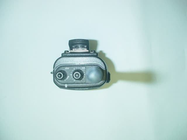
ROGERS LABS, INC. Genex Electronics Co. LTD 4405 W. 259th Terrace MODEL: GM-18 Louisburg, KS 66053 Test #: 020723 FCCID#: PM3GM22 Phone/Fax: (913) 837-3214 Test to: FCC Parts 2 and 95 Page 1 of 2 GM18Photos.doc 7/30/2002 Equipment photographs for GM-18. ROGERS LABS, INC. Genex Electronics Co. LTD 4405 W. 259th Terrace MODEL: GM-18 Louisburg, KS 66053 Test #: 020723 FCCID#: PM3GM22 Phone/Fax: (913) 837-3214 Test to: FCC Parts 2 and 95 Page 2 of 2 GM18Photos.doc 7/30/2002
ID Label/Location Info
ROGERS LABS, INC. Genex Electronics Co. LTD 4405 W. 259th Terrace MODEL: GM-18 Louisburg, KS 66053 Test #: 020723 FCCID#: PM3GM22 Phone/Fax: (913) 837-3214 Test to: FCC Parts 2 and 95 Page 1 of 1 GM18Label.doc 7/30/2002 FCC ID label and location photographs for GM-18. GM22
Internal Photos
ROGERS LABS, INC. Genex Electronics Co. LTD 4405 W. 259th Terrace MODEL: GM-18 Louisburg, KS 66053 Test #: 020723 FCCID#: PM3GM22 Phone/Fax: (913) 837-3214 Test to: FCC Parts 2 and 95 Page 1 of 1 GM18IntPho.doc 8/6/2002 Internal photographs of Printed circuit boards for GM-18.
Parts List/Tune Up Info
GM-18 02-07-14 2. ALIGNMENT INSTRUCTIONS WARNING Any repairs or adjustment should be made under the supervision of a qualified radio-telephone technician. 2-1. VCO 2-1-1. Power Supply Voltage The power supply voltage should be set for 6.0 Vdc. 2-1-1. VCO Adjustment A. Connect high impedance voltmeter between R143 and C167 B. Adjust L3 for 1.0V. 2-2. TRANSMITTER 2-2-1. Power Supply Voltage The power supply voltage should be set for 6.0 V DC measured at the radio during transmit. Periodically check the supply voltage during the alignment procedure. 2-2-2. Frequency Setting A. Connect a frequency counter or Communications Service Monitor to the antenna connector through an RF power attenuates (5 watt minimum rating, 20 dB minimum attenuation). B. Depress the PTT switch. C. Adjust the TCXO such that output frequency is equal to the channel. Frequency with a maximum error of ±300 Hz. D. Adjust CT101 for ±300 Hz. E. Release the PTT switch. 2-2-3. Output Power Alignment A. Set the power supply voltage for 6.0 V DC. B. Connect a communications Service Monitor or a wattmeter and dummy load to the antenna connector. C. Depress the PTT switch. D. To be convinced for 1.5 watt output power with a maximum error of ±0.2 watt. E. Release the PTT switch. 2-2-4. Deviation Adjustment A. Connect an audio generator to the microphone jack JIG. The audio frequency should be set at 1 KHz B. Connect an FM deviation meter or communication Service Monitor to the antenna connector Through an RF power attenuates (5 watt minimum rating, 20 dB minimum attenuates ). Set the monitor to read peak deviation. C. Depress the PTT switch. D. Adjust the audio generator level 100 mV rms. E. Adjusted for 2.3 KHz maximum deviation. F. Release the PTT switch. GM-18 02-07-14 2-3. RECEIVER Note : Insure that the proper channel has been selected before proceedings with the alignment procedure. 2-3-1. Power Supply Voltage. The proper voltage for testing is 6.0 V DC. 2-3-2. 12dB SINAD Alignment A. Connect an RF signal generator or Communications Service Monitor to the antenna connect. B. Connect a SINAD meter and oscilloscope across the speaker terminals. C. Set the output level of the RF signal generator for –47 dBm the generator should be set for 1.5 KHz deviation of a 1 KHz tone. D. Set the audio output level for 0.6 Vrms by adjusting volume. E. Fixed L106 for maximum audio output. F. Reduce the output level of the RF signal generator for produce a 12 dB SINAD indication. 2-3-3. Squelch Alignment A. Connect an RF signal generator or Communications Service Monitor to the antenna connects. B. Connect a SINAD meter and oscilloscope across the speaker terminals. C. Set the output level of the RF signal generator for –125 dBm the generator should be set for 1.5 KHz deviation of a 1 KHz tone. D. Set the audio output level for 0.6 Vrms by adjusting volume. E. Adjust RV101 for audio output disappears.
RF Exposure Info
Test Report S/N: 101602-295PM3 Test Date(s): October 17, 2002 FCC SAR Evaluation © 2002 Celltech Research Inc.1 of 21 Celltech Research Inc. declares under its sole responsibility that this device was found to be in compliance with the Specific Absorption Rate (SAR) RF exposure requirements specified in FCC §2.1093. The device was tested in accordance with the measurement standards and procedures specified in FCC OET Bulletin 65, Supplement C, Edition 01-01 (General Population / Uncontrolled Exposure). I attest to the accuracy of data. All measurements were performed by me or were made under my supervision and are correct to the best of my knowledge and belief. I assume full responsibility for the completeness of these measurements and vouch for the qualifications of all persons taking them. This test report shall not be reproduced partially, or in full, without the prior written approval of Celltech Research Inc. The results and statements contained in this report pertain only to the device(s) evaluated. Russell W. Pipe Senior Compliance Technologist Celltech Research Inc. DECLARATION OF COMPLIANCE SAR EVALUATION Test Lab CELLTECH RESEARCH INC. Testing and Engineering Lab 1955 Moss Court Kelowna, B.C. Canada V1Y 9L3 Phone: 250-448-7047 Fax: 250-448-7046 e-mail: [email protected] web site: www.celltechlabs.com Applicant Information GENEX ELECTRONICS CO., LTD. 3263 HA-AHN Industrial Zone 201 HA-AHN 3-Dong Kwang Myung-City Korea 423-754 Rule Part(s):FCC 47 CFR §2.1093 Test Procedure(s):FCC OET Bulletin 65, Supplement C (01-01) Device Type:Portable UHF GMRS/FRS PTT Radio Transceiver FCC ID:PM3GM22 Model(s):GM22 Modulation:FM (UHF) Tx Frequency Range:462.5500 - 462.7250 MHz (GMRS Channels 15-22) 462.5625 - 462.7125 MHz (FRS Channels 1-7) 467.5625 - 467.7125 MHz (FRS Channels 8-14) RF Conducted Power Tested:1.5 Watts (GMRS) Antenna Type(s):Fixed Battery Type(s):1.5V AAA Alkaline (x4) or 1.2V AAA NiMH (x4) Body-Worn Accessories:Belt-Clip, Ear-Microphone Max. SAR Measured:1.13 W/kg Face-held / 0.767 W/kg Body-worn Test Report S/N: 101602-295PM3 Test Date(s): October 17, 2002 FCC SAR Evaluation © 2002 Celltech Research Inc.2 of 21 TABLE OF CONTENTS 1.0INTRODUCTION..................................................................... 3 2.0DESCRIPTION OF DUT............................................................ 3 3.0SAR MEASUREMENT SYSTEM ............................................... 4 4.0MEASUREMENT SUMMARY..................................................... 5 5.0DETAILS OF SAR EVALUATION............................................... 6 6.0EVALUATION PROCEDURES................................................... 7 7.0SYSTEM VALIDATION............................................................. 8 8.0SIMULATED TISSUES............................................................. 9 9.0SAR LIMITS........................................................................... 9 10.0SYSTEM SPECIFICATIONS......................................................10 11.0PROBE SPECIFICATION.........................................................11 12.0SAM PHANTOM......................................................................11 13.0LARGE PLANAR PHANTOM.....................................................11 14.0DEVICE HOLDER....................................................................11 15.0TEST EQUIPMENT LIST...........................................................12 16.0MEASUREMENT UNCERTAINTIES............................................13 17.0REFERENCES.......................................................................14 APPENDIX A - SAR MEASUREMENT DATA.............................................15 APPENDIX B - SYSTEM VALIDATION.....................................................16 APPENDIX C - DIPOLE CALIBRATION...................................................17 APPENDIX D - PROBE CALIBRATION....................................................18 APPENDIX E - MEASURED FLUID DIELECTRIC PARAMETERS................19 APPENDIX F - SAM PHANTOM CERTIFICATE OF CONFORMITY..............20 APPENDIX G - SAR TEST SETUP & DUT PHOTOGRAPHS........................21 Test Report S/N: 101602-295PM3 Test Date(s): October 17, 2002 FCC SAR Evaluation © 2002 Celltech Research Inc.Genex Electronics Co., Ltd. FCC ID: PM3GM22 (Model: GM22)3 of 21 Portable UHF GMRS/FRS PTT Radio Transceiver (462-467MHz) 1.0 INTRODUCTION This measurement report demonstrates compliance of the Genex Electronics Co., Ltd. Model: GM22 Portable UHF GMRS/FRS PTT Radio Transceiver FCC ID: PM3GM22 with FCC 47 CFR §2.1093 (see reference [1]) (General Population / Uncontrolled Exposure environment). The test procedures described in FCC OET Bulletin 65, Supplement C, Edition 01-01 (see reference [2]) were employed. A description of the product and operating configuration, detailed summary of the test results, methodology and procedures used in the evaluation, equipment used, and the various provisions of the rules are included within this test report. 2.0 DESCRIPTION of Device Under Test (DUT) FCC Rule Part(s)47 CFR §2.1093 Test ProcedureFCC OET Bulletin 65, Supplement C (01-01) Device TypePortable GMRS/FRS PTT Radio Transceiver FCC IDPM3GM22 Model(s)GM22 Serial No.Pre-production ModulationFM (UHF) Tx Frequency Range 462.5500 - 462.7250 MHz (GMRS Channels 15-22) 462.5625 - 462.7125 MHz (FRS Channels 1-7) 467.5625 - 467.7125 MHz (FRS Channels 8-14) RF Conducted Power Tested1.5 Watts (GMRS) Battery Type(s)1.5V AAA Alkaline (x4) or 1.2V AAA NiMH (x4) Antenna Type(s)Fixed Body-Worn Accessories TestedBelt-Clip, Ear-Microphone Test Report S/N: 101602-295PM3 Test Date(s): October 17, 2002 FCC SAR Evaluation © 2002 Celltech Research Inc.Genex Electronics Co., Ltd. FCC ID: PM3GM22 (Model: GM22)4 of 21 Portable UHF GMRS/FRS PTT Radio Transceiver (462-467MHz) 3.0 SAR MEASUREMENT SYSTEM Celltech Research SAR measurement facility utilizes the Dosimetric Assessment System (DASY™) manufactured by Schmid & Partner Engineering AG (SPEAG™) of Zurich…
Text truncated - open the document above for the full version.
Test Report
TEST REPORT For APPLICATION of CERTIFICATION For Genex Electronics Co. LTD 3263 HA-AHN Industrial Zone 201 HA-AHN 3-Dong KWANG MYUNG-CITY 423-754 KOREA Clark Cheon Manager MODEL: GM-18 General Mobile Radio Services (GMRS) UHF TRANSCEIVER FREQUENCY: 462 - 467 MHz FCC ID: PM3 GM22 Test Date: July 23, 2002 Certifying Engineer: Scot D. Rogers ROGERS LABS, INC. 4405 West 259th Terrace Louisburg, KS 66053 Phone: (913) 837-3214 FAX: (913) 837-3214 This report shall not be reproduced except in full, without the written approval of the laboratory. This report must not be used by the client to claim product endorsement by NVLAP or any agency of the U.S. Government. ROGERS LABS, INC. 4405 West 259 th Terrace Louisburg, KS 66053 Phone / Fax (913) 837-3214 NVLAP Accredited Laboratory NVLAP Lab Code: 200087-0 ROGERS LABS, INC. Genex Electronics Co. LTD 4405 West 259 th Terrace MODEL: GM-18 GMRS UHF Transceiver Louisburg, KS 66053 Test #:02072302 FCC ID#: PM3 GM22 SN: Set 1 Phone/Fax: (913) 837-3214 Test to: FCC Parts 2, 15, and 95 Page 2 of 21 CERTIFICATION\GenexGM18A 08/26/2002 TABLE OF CONTENTS FORWARD: 3 LIST OF TEST EQUIPMENT 3 2.1033(C) APPLICATION FOR CERTIFICATION 4 2.1046 RF POWER OUTPUT 5 Measurements Required: 5 Test Arrangement: 5 Results: 5 2.1047 MODULATION CHARACTERISTICS 6 Measurements Required: 6 Test Arrangement: 6 Results: 7 2.1049 OCCUPIED BANDWIDTH 9 Measurements Required: 9 Test Arrangement: 9 Results: 9 2.1051 SPURIOUS EMISSIONS AT ANTENNA TERMINALS 11 Measurements Required: 11 Test Arrangement: 11 Results: 12 2.1053 FIELD STRENGTH OF SPURIOUS RADIATION 13 Measurements Required: 13 Test Arrangement: 13 Results: 14 2.1055 FREQUENCY STABILITY 15 Measurements Required: 15 Test Arrangement: 16 Results: 17 APPENDIX 18 NVLAP Accredited Laboratory NVLAP Lab Code: 200087-0 ROGERS LABS, INC. Genex Electronics Co. LTD 4405 West 259 th Terrace MODEL: GM-18 GMRS UHF Transceiver Louisburg, KS 66053 Test #:02072302 FCC ID#: PM3 GM22 SN: Set 1 Phone/Fax: (913) 837-3214 Test to: FCC Parts 2, 15, and 95 Page 3 of 21 CERTIFICATION\GenexGM18A 08/26/2002 FORWARD: In accordance with the Federal Communications Code of Federal Regulations, dated October 1, 2001, Part 2 Subpart J, Paragraphs 2.907, 2.911, 2.913, 2.915, 2.925, 2.926, 2.1031 through 2.1057, applicable paragraphs of Parts 15, and 95, the following is submitted: List of Test Equipment A Hewlett Packard 8591EM and or 8562A Spectrum Analyzer was used as the measuring device for the emissions testing. The analyzer settings used are described in the following table. Refer to the Appendix for a complete list of Test Equipment. HP 8591EM SPECTRUM ANALYZER SETTINGS CONDUCTED EMISSIONS: RBW AVG. BW DETECTOR FUNCTION 9 kHz 30 kHz Peak/Quasi Peak RADIATED EMISSIONS (30 – 1000 MHz): RBW AVG. BW DETECTOR FUNCTION 120 kHz 300 kHz Peak/Quasi Peak HP 8562A SPECTRUM ANALYZER SETTINGS RADIATED EMISSIONS (1 – 40 GHz): RBW AVG. BW DETECTOR FUNCTION 1 MHz 1 MHz Peak/Average ANTENNA CONDUCTED EMISSIONS: RBW AVG. BW DETECTOR FUNCTION 120 kHz 300 kHz Peak NVLAP Accredited Laboratory NVLAP Lab Code: 200087-0 ROGERS LABS, INC. Genex Electronics Co. LTD 4405 West 259 th Terrace MODEL: GM-18 GMRS UHF Transceiver Louisburg, KS 66053 Test #:02072302 FCC ID#: PM3 GM22 SN: Set 1 Phone/Fax: (913) 837-3214 Test to: FCC Parts 2, 15, and 95 Page 4 of 21 CERTIFICATION\GenexGM18A 08/26/2002 2.1033(c) Application for Certification (1) Manufacturer: Genex Electronics Co. LTD 3263 HA-AHN Industrial Zone 201 HA-AHN 3-Dong KWANG MYUNG-CITY 423-754 KOREA Marketer/Vendor: TEKK Incorporated 226 NW Parkway Kansas City, MO 64150 (2) Identification: Model: GM-18 S/N: Set 1 FCC I.D.: PM3 GM22 (3) Instruction Book: Refer to exhibit for Draft Instruction Manual. (4) Emission Type: 7K00F3E (5) Frequency Range: 462 and 467 MHz (6) Operating Power Level: 1.5 Watts (High Power) 0.5 Watts (Low Power) (7) Max P o : 1.5 Watts (8) Power into final amplifier: 1.5 Watt Unit: 4.80 Watts (6.0V @ 0.8A) (9) Tune Up Procedure for Output Power: Refer to Exhibit for Transceiver Alignment Procedure. (10) Circuit Diagrams; description of circuits, frequency stability, spurious suppression, and power and modulation limiting: Refer to Exhibit for Circuit Diagrams. Refer to Exhibit for Theory of Operation. (11) Photograph or drawing of the Identification Plate: Refer to Exhibit for Photograph or Drawing. (12) Drawings of Construction and Layout: Refer to Exhibit for Drawings of Components Layout and Chassis Drawings. (13) Detail Description of Digital Modulation: Not applicable. NVLAP Accredited Laboratory NVLAP Lab Code: 200087-0 ROGERS LABS, INC. Genex Electronics Co. LTD 4405 West 259 th Terrace MODEL: GM-18 GMRS UHF Transceiver Louisburg, KS 66053 Test #:02072302 FCC ID#: PM3 GM22 SN: Set 1 Phone/Fax: (913) 837-3214 Test to: FCC Parts 2, 15, and 95 Page 5 of 21 CERTIFICATION\GenexGM18A 08/26/2002 2.1046 RF Power Output Measurements Required: Measurements shall be made to establish the radio frequency power delivered by the transmitter into the standard output termination. The power output shall be monitored and recorded and no adjustment shall be made to the transmitter after the test has begun, except as noted below: If the power output is adjustable, measurements shall be made for the highest and lowest power levels. Test Arrangement: The radio frequency power output was measured at the antenna terminal by replacing the antenna with a spectrum analyzer, 6-dB attenuation. The spectrum analyzer had an impedance of 50W to match the impedance of the standard antenna. A HP 8591EM Spectrum Analyzer was used to measure the radio frequency power at the antenna port. The data was taken in dBm and converted to watts as shown in the following Table. Refer to the following table for maximum output power of the transmitter. Data shown represents the worst-case conditions of the unit. Data was taken per Paragraph 2.1046(a) and applicable parts of Parts 2 and 95. Results: FREQUENCY P dBm P mw P w 462.5625 31.69 1,475.7 1…
Text truncated - open the document above for the full version.
Contact Information
Applicant
Clark Cheon(Manager)
Test Firm
Rogers Labs, Inc.Scot Rogers
Technical Specifications
| # | Rule Parts | Frequency Range | Power Output | Emission | Tolerance |
|---|---|---|---|---|---|
| 4 | 95A | 467.55 MHz - 467.725 MHz | 479.00 mW | 12K0F3E | 5 ppm |
Other Applications from Genex Telecom Co., Ltd.
PM3GT40
Dec 08, 2004UHF LMRS TRANSMITTER
Equipment Class
TNF - Licensed Non-Broadcast Transmitter Held to Face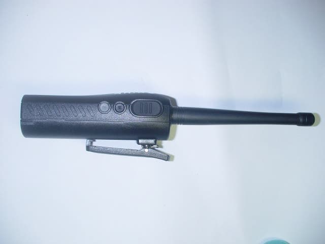
PM3GT10
Dec 08, 2004UHF LMRS TRANSMITTER
Equipment Class
TNF - Licensed Non-Broadcast Transmitter Held to Face
PM3MT900
Nov 28, 2004LAND MOBILE RADIO SERVICE GMRS TRANSMITTER
Equipment Class
TNB - Licensed Non-Broadcast Station Transmitter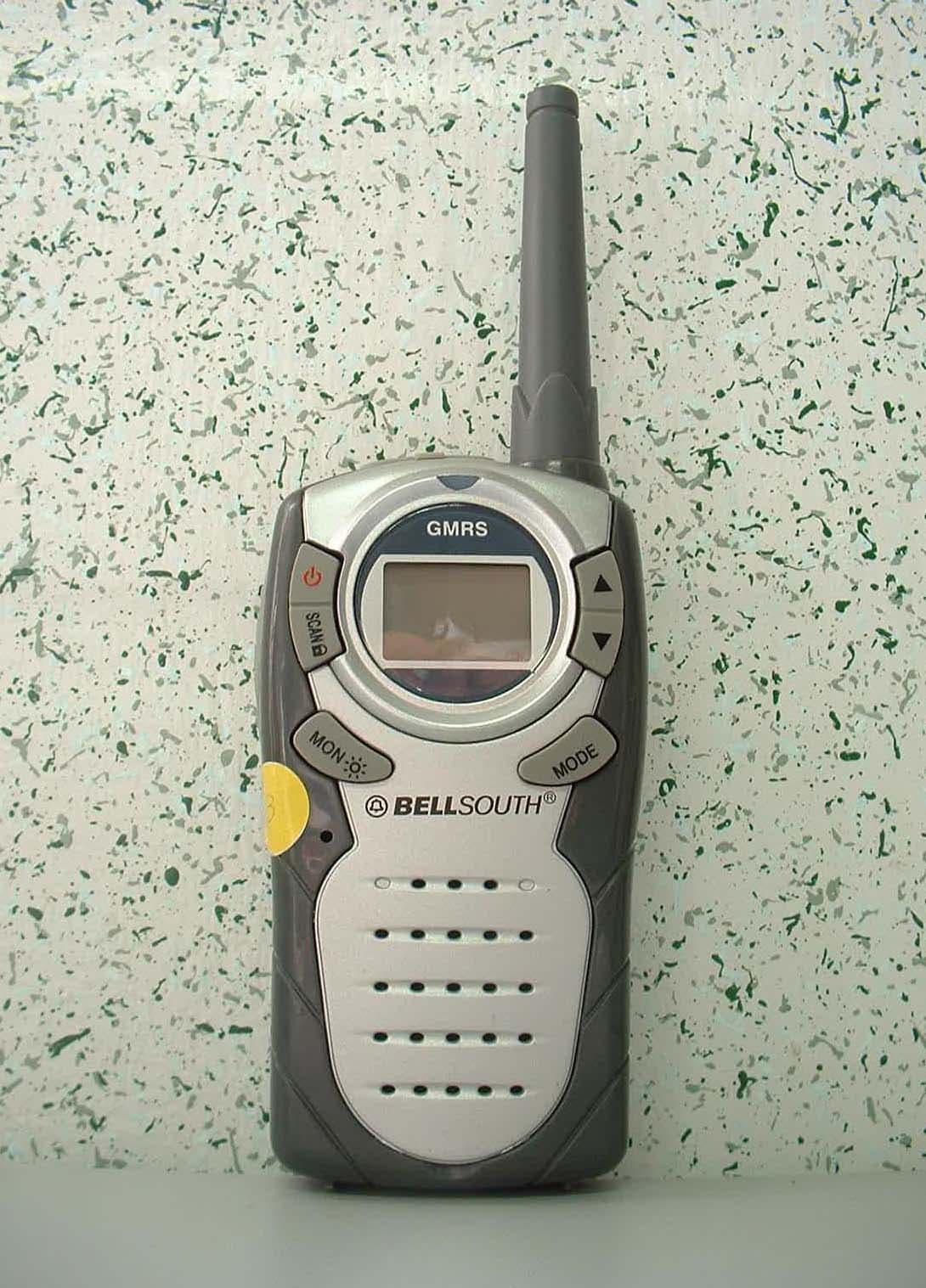
PM3GR5500
Jul 18, 2004GMRS/FRS UHF Transceiver
Equipment Class
FRF - Part 95 Family Radio Face Held Transmitter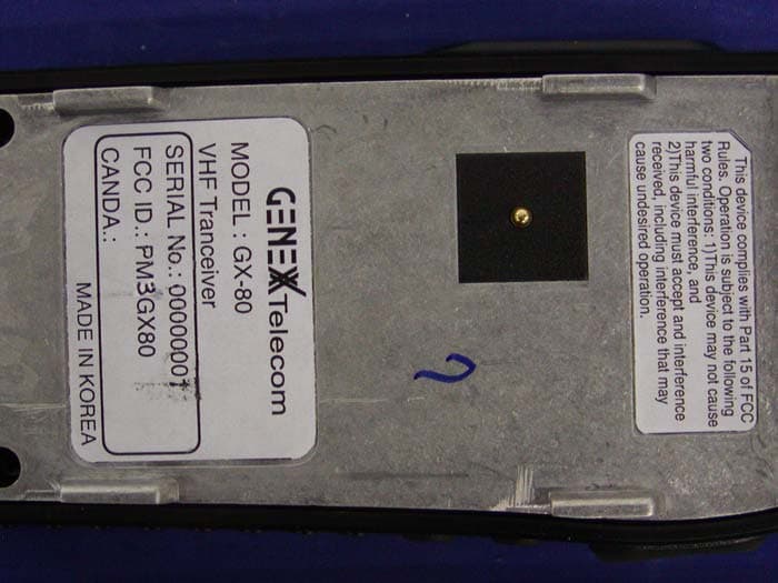
PM3GX80
Jul 01, 2004Transceiver, VHF, PTT
Equipment Class
TNF - Licensed Non-Broadcast Transmitter Held to Face