PM3GR2000GMRS UHF Transceiver
Genex Telecom Co., Ltd.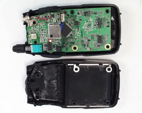
Click to zoom
Application Details
- Equipment Class
- TNF - Licensed Non-Broadcast Transmitter Held to Face
- Date of Grant
- May 07, 2002
- Application Purpose
- Original Equipment
- Date of Application
- Feb 03, 2002
- Equipment Note
- GMRS UHF Transceiver
- Frequency Range
- 462.55000000 - 467.72500000
- Company
- Genex Telecom Co., Ltd.
- Country
- South Korea
Documents & Files
Document Text
Text extracted from the exhibit documents filed with the FCC. Open a document above to read the original.
Users Manual
GR-2000 Basic Operation 01-12-20 1 of 8 1. General Specification - Power On/Off Volume - PTT Key : Side [ Tact SW ] - Monitor Key : Side [ Tact SW ] - UP Key : Top - Down Key : Top - SCAN Key : Top - CALL Key : Top - Function Key : Top - EXT Mic/Charge Jack[ 2.5 ?] - EXT Speaker Jack[ 3.5] 2. Function Flow Chart F Channel CTCSS PWR Hi/Low DW VOX BEEP Roger Beep Ringer Tone Vibration F 3. LCD Display GR-2000 Basic Operation 01-12-20 2 of 8 4. Front, Side, Top Overview GR-2000 Basic Operation 01-12-20 3 of 8 5. Operating Instruction 1) On/Off & Volume control Switch - Radio ON : Rotate the switch clockwise unitl you here a ‘click’. All indicators will appear momentarily on the LCD and you will hear a short beep. - Radio Off :Rotate the switch counter colckwisw until all indicators disappear on the LCD. - Volume setting : Rotate On/Off Volume switch to mid position or adjust level that is most comfortable for you. 2) Setting the Channel GR-2000 has 15 main channels. To select the channel - Turn the radio on. - Press up[ ] or down[] button to choose the channel. 3) Setting the Tone Code(CTCSS) GR-2000 has 38 CTCSS Codes To set the Tone Codes(CTCSS) - Press Function[F] button once more,[XX oF up to 38] will appear and tone code digit will blink on the LCD. " 00 " means no CTCSS code. - Press up[ ] or down[] button to choose the desired sub-channel to use. - Press the PTT button or Function [F] to confirm. 4) Setting the Transmit Power HI/LO - HI : 1.8W TX power - LO : 500mW TX power To set the TX output power - Press the Function[F] button until the [ Po LO or HI ] appears. - Press the up[] button or down [] button to set the TX power - Press the PTT button or Function [F] to confirm. - HI or LO will appear on the LCD. - If the battery is in low condition, the TX Power will be switched to LO automatically. Even though the TX power is set to HI. 5) Setting the DW(dual watch) and CTCSS in DW mode. GR-2000 Basic Operation 01-12-20 4 of 8 To active the DW mode - Press the Function[F] button until the [ oF or 1 up to 15] and DW icon blink on the LCD. - Press the up[ ] button or down [] button to choose the channel. - " oF " means no DW mode. - Press the PTT button or Function[F] button to confirm. - DW icon will appear on the LCD. To stop the dual watch(DW) - Press the "S" Scan button, the unit will stop the dual watch and will return to normal operation and DW icon will disappear from the LCD. - DW icon will disappear from the LCD. 6) VOX (Voice Operated Transmission) This option enables you to have hands-free conversation. You do not have to operate the PTT button each time when you want to transmit. You can also choose the VOX sensitivity to suit your environment of operation. (Ex ; noisy road, motor bike, factory etc.) To set the VOX mode. - Press the Function[F] button until the [ Uo oF or x ] appears. x is a vox level - VOX icon will be appeared on the LCD. To set the VOX level - Press the up[] button or down [] button to set the VOX level from 1 to 3. "oF" is disable the VOX function. " 3 " is most sensitive. " 1 " is least sensitive. - Press the PTT button or Function [F] to confirm. GR-2000 Basic Operation 01-12-20 5 of 8 7) Beep tone To activate or disable the beep tone - Press the Function[F] button until [bP on or oF] and the BELL[] icon blink on the LCD. - Press the up[] button or down [] button. - Press the PTT button or Function[F] button to confirm. 8) Roger tone This feature will give the tone signal to other parties when transmitting finished (when PTT button is released.) To activate or disable the Roger tone - Press the Function[F] button until [rb on or oF] and the Roger [] icon blink on the LCD. - Press the up[] button or down [] button. - Press the PTT button or Function [F] to confirm. 9) Setting the Ringer This feature provides 3 user selectable call ringer signal and vibration. To set your favorite call ringer signal. - Press the Function[F] button until the [ CA 1 or up to 3 ] appears on the LCD. - Press the up[] button or down [] button to select the call melody type. - Press the PTT button to confirm. - To activate the call , click the "PTT" button twice quickly. 10) Setting the Vibration Modes To set for Vibration - Press the Function[F] button until the [ Ub on or oF ] and Vibrator[ ] icon blink on the LCD - Press the up[] button or down [] button. - Press the PTT button or Function [F] to confirm. 11) Transmitting - Press and hold the PTT button (The “TX” LED will light with red color). - Speak slowly and clearly - To stop the transmission, release the PTT button GR-2000 Basic Operation 01-12-20 6 of 8 - If there are no more receiving signal for 5 seconds, the unit will go into power save mode and then the “TX” LED will blink with a green color. 12) Receiving The coding feature reduces the possibility of interference and provides enhanced communication. You can only listen to a call that has correct matching code. Important ; Before transmitting or receiving to the other parties ; - Correct channel is selected ( 1 to 15 ) and - Correct code is set ( 00 to 38 ) 13) Channel Scanning This feature allows you to monitor all activated channels while scanning. To activate the Scan - Press the Scan[S] button - Radio will begin scanning. - When in scan mode, the display will show each scanning channel. - After an activated channel is scanned and received signal and then if there is no more signal, the scan will resume automatically. To disable the Scan - Press the Scan[S] button, the unit will stop the scanning. - SCAN icon indicator will disappear from the LCD - The unit will return to home channel. 14) Call - Press the Call[C] button (he “TX” LED will light with red color). 15) Monitoring the channel It is used for listening the week signal or to hear all activities on the channel by manually overriding channel sub tone code setting. To activate the Monitor feature - Press and hold the Monitor[M] button for over two seconds. - When you hear the sound, release the Monitor[M…
Text truncated - open the document above for the full version.
Users Manual
iii this radio by the manufacturer or an antenna specifically authorized by the manufacturer for use with this radio. • DO NOT transmit for more than 50% of total radio use time ( “50% duty cycle”). Transmitting more than 50% of the time can cause FCC RF exposure compliance requirements to be exceeded. The radio is transmitting when the “TX indicator” lights red. You can cause the radio to transmit by pressing the “PTT” switch. • ALWAYS use authorized accessories (antennas, batteries, belt clips, speaker/mics, etc). Use of unauthorized accessories can cause the FCC RF exposure compliance requirements to be ex- ceeded. • ALWAYS keep the antenna at least 2.5 cm (1 inch) away from the body when transmitting and only use the belt-clips, listed in p. 22, when attaching the radio to your belt, etc., to ensure FCC RF ex- posure compliance requirements are not exceeded. To provide the recipients of your transmission the best sound quality, hold the an- tenna at least 5 cm (2 inches) from mouth, and slightly off to one side. The information listed above provides the user with the information needed to make him or her aware of RF exposure, and what to do to assure that this radio operates within the FCC RF exposure limits of this radio. Electromagnetic Interference/Compatibility During transmissions, your radio generates RF energy that can possibly cause interference with other devices or systems. To avoid such interference, turn off the radio in areas where signs are posted to do so. DO NOT operate the transmitter in areas that are sensitive to electromagnetic radiation such as hospitals, aircraft, and blasting sites. Your radio generates RF electromagnetic energy during transmit mode. This radio is de- signed for and classified as “Occupational Use Only”, meaning it must be used only during the course of employment by individuals aware of the hazards, and the ways to minimize such hazards. This radio is NOT intended for use by the “General Popula- tion” in an uncontrolled environment. This radio has been tested and complies with the FCC RF expo- sure limits for “Occupational Use Only.” In addition, the radio complies with the following Standards and Guidelines with regard to RF energy and electromagnetic energy levels and evaluation of such levels for exposure to humans: • FCC OET Bulletin 65 Edition 97-01 Supplement C, Evaluating Compliance with FCC Guidelines for Human Exposure to Radio Frequency Electromagnetic Fields. • American National Standards Institute (C95.1 – 1992), IEEE Stan- dard for Safety Levels with Respect to Human Exposure to Radio Frequency Electromagnetic Fields, 3 kHz to 300 GHz. • American National Standards Institute (C95.3 – 1992), IEEE Rec- ommended Practice for the Measurement of Potentially Hazardous Electromagnetic Fields – RF and Microwave. To ensure that your exposure to RF electromag- netic energy is within the FCC allowable limits for occupational use, always adhere to the following guidelines: •DO NOToperate the radio without a proper antenna attached, as this may damage the radio and may also cause you to exceed FCC RF exposure limits. A proper antenna is the antenna supplied with WARNING CAUTION SAFETY TRAINING INFORMATION
Cover Letter(s)
January 15, 2002 Timco Engineering Inc. 849 NW State Road 45 Newberry, FL 32669 Telephone 888.472.2424 Fax 352.472.2030 Applicant: Genex Electronics Co. LTD 3263 HA-AHN Industrial Zone 201 HA-AHN 3-Dong KWANG MYUNG-CITY 423-754 KOREA FRN 0006-1433-33 Re: Confidentiality of schematics Equipment: GMRS Transceiver FCC ID: PM3 GR2000 Gentlemen: It is requested that the information contained in the block diagrams, operational description and schematics of the application be held confidential per Section 0.459. Please use this information in obtaining a grant of certification for the transceiver, for use in the general mobile radio service, model number GR-2000. In support of this request, we submit the following: 1. Identification of the specific information for which confidential treatment is sought: The materials set fourth in the Operational Description, Block Diagram, Parts List, and Schematics, are those for which confidentiality is sought. 2. Identification of the Commission proceeding in which the information was submitted or a description of the circumstances giving rise to the submission: The proceeding is that involving the application for equipment authorization (certification) under FCC ID No: PM3 GR2000 3. Explanation of the degree to which the information is commercial or financial, or contains a trade secret or is privileged: This material includes a detailed theory of operation and circuit diagrams, (schematics, part list, and Block diagrams). As such this material is treated as highly confidential business information and is not subject to public view. Should you require any further information, please contact the undersigned. Thank you for your consideration in this matter. Sincerely, Scot Rogers Rogers Labs, Inc. ROGERS LABS, INC. 4405 West 259 th Terrace Louisburg, KS 66053 Phone / Fax (913) 837-3214
Cover Letter(s)
C:\windows\TEMP\probonholdemail.doc TIMCO TIMCOTIMCO TIMCO ENGINEERING INC. 849 NW State Road 45 Newberry, Florida 32669 http://www.timcoengr.com 888.472.2424 F 352.472.2030 email: tei@t imcoengr.com 31 January 2002 FCC SUBJECT: GENEX ELECTRONICS CO., LTD. FCC ID: PM3GR2000 MODEL: To Whom It May Concern: 1. The MPE calculation should be for a minimum operating distance of 5.0cm from the face. 2. The grant will list the power output as 2.0W EIRP. This application is on hold until these questions are resolved. Please direct all responses to [email protected]. DO NOT HIT REPLY! Responses should also contain the Reference information, as shown at the top of this message. If the information required is not received after the 2 nd Request and within 30 days, this job will be closed and will incur additional fee of $400.00 to re-open. Sincerely, Sid Sanders
External Photos
ROGERS LABS, INC. Genex Electronics Co. LTD 4405 W. 259th Terrace MODEL: GR-2000 Louisburg, KS 66053 Test #: 011231 FCCID#: PM3GR2000 Phone/Fax: (913) 837-3214 Test to: FCC Parts 2 and 95 Page 1 of 3 GR2000Photos.doc 1/8/2002 Equipment photographs for GR-2000. ROGERS LABS, INC. Genex Electronics Co. LTD 4405 W. 259th Terrace MODEL: GR-2000 Louisburg, KS 66053 Test #: 011231 FCCID#: PM3GR2000 Phone/Fax: (913) 837-3214 Test to: FCC Parts 2 and 95 Page 2 of 3 GR2000Photos.doc 1/8/2002 ROGERS LABS, INC. Genex Electronics Co. LTD 4405 W. 259th Terrace MODEL: GR-2000 Louisburg, KS 66053 Test #: 011231 FCCID#: PM3GR2000 Phone/Fax: (913) 837-3214 Test to: FCC Parts 2 and 95 Page 3 of 3 GR2000Photos.doc 1/8/2002
ID Label/Location Info
ROGERS LABS, INC. Genex Electronics Co. LTD 4405 W. 259th Terrace MODEL: GR-2000 Louisburg, KS 66053 Test #: 011231 FCCID#: PM3GR2000 Phone/Fax: (913) 837-3214 Test to: FCC Parts 2 and 95 Page 1 of 1 GR2000Label.doc 1/8/2002 FCC ID label and location photographs for GR-2000.
ID Label/Location Info
iii this radio by the manufacturer or an antenna specifically authorized by the manufacturer for use with this radio. • DO NOT transmit for more than 50% of total radio use time ( “50% duty cycle”). Transmitting more than 50% of the time can cause FCC RF exposure compliance requirements to be exceeded. The radio is transmitting when the “TX indicator” lights red. You can cause the radio to transmit by pressing the “PTT” switch. • ALWAYS use authorized accessories (antennas, batteries, belt clips, speaker/mics, etc). Use of unauthorized accessories can cause the FCC RF exposure compliance requirements to be ex- ceeded. • ALWAYS keep the antenna at least 2.5 cm (1 inch) away from the body when transmitting and only use the belt-clips, listed in p. 22, when attaching the radio to your belt, etc., to ensure FCC RF ex- posure compliance requirements are not exceeded. To provide the recipients of your transmission the best sound quality, hold the an- tenna at least 5 cm (2 inches) from mouth, and slightly off to one side. The information listed above provides the user with the information needed to make him or her aware of RF exposure, and what to do to assure that this radio operates within the FCC RF exposure limits of this radio. Electromagnetic Interference/Compatibility During transmissions, your radio generates RF energy that can possibly cause interference with other devices or systems. To avoid such interference, turn off the radio in areas where signs are posted to do so. DO NOT operate the transmitter in areas that are sensitive to electromagnetic radiation such as hospitals, aircraft, and blasting sites. Your radio generates RF electromagnetic energy during transmit mode. This radio is de- signed for and classified as “Occupational Use Only”, meaning it must be used only during the course of employment by individuals aware of the hazards, and the ways to minimize such hazards. This radio is NOT intended for use by the “General Popula- tion” in an uncontrolled environment. This radio has been tested and complies with the FCC RF expo- sure limits for “Occupational Use Only.” In addition, the radio complies with the following Standards and Guidelines with regard to RF energy and electromagnetic energy levels and evaluation of such levels for exposure to humans: • FCC OET Bulletin 65 Edition 97-01 Supplement C, Evaluating Compliance with FCC Guidelines for Human Exposure to Radio Frequency Electromagnetic Fields. • American National Standards Institute (C95.1 – 1992), IEEE Stan- dard for Safety Levels with Respect to Human Exposure to Radio Frequency Electromagnetic Fields, 3 kHz to 300 GHz. • American National Standards Institute (C95.3 – 1992), IEEE Rec- ommended Practice for the Measurement of Potentially Hazardous Electromagnetic Fields – RF and Microwave. To ensure that your exposure to RF electromag- netic energy is within the FCC allowable limits for occupational use, always adhere to the following guidelines: •DO NOToperate the radio without a proper antenna attached, as this may damage the radio and may also cause you to exceed FCC RF exposure limits. A proper antenna is the antenna supplied with WARNING CAUTION SAFETY TRAINING INFORMATION
Internal Photos
ROGERS LABS, INC. Genex Electronics Co. LTD 4405 W. 259th Terrace MODEL: GR-2000 Louisburg, KS 66053 Test #: 011231 FCCID#: PM3GR2000 Phone/Fax: (913) 837-3214 Test to: FCC Parts 2 and 95 Page 1 of 3 GR2000Internal.doc 1/30/2002 Internal photographs of Printed circuit boards for GR-2000. Digital printed circuit board top and bottom. ROGERS LABS, INC. Genex Electronics Co. LTD 4405 W. 259th Terrace MODEL: GR-2000 Louisburg, KS 66053 Test #: 011231 FCCID#: PM3GR2000 Phone/Fax: (913) 837-3214 Test to: FCC Parts 2 and 95 Page 2 of 3 GR2000Internal.doc 1/30/2002 RF printed circuit board top. RF printed circuit board bottom.
Parts List/Tune Up Info
ROGERS LABS, INC. Genex Electronics Co. LTD 4405 W. 259th Terrace MODEL: GR-2000 Louisburg, KS 66053 Test #: 011231 FCCID#: PM3GR2000 Phone/Fax: (913) 837-3214 Test to: FCC Parts 2 and 95 Page 1 of 1 GR2000TunProc.doc 1/8/2002 ALIGNMENT INSTRUCTIONS WARNING Any repairs or adjustment should be made under the supervision of a qualified radio-telephone technician. 2-1. TRANSMITTER 2-1-1. Power Supply Voltage The power supply voltage should be set for 6.0 V DC measured at the radio during transmit. Periodically check the supply voltage during the alignment procedure. 2-1-2. Frequency Setting A. Connect a frequency counter or Communications Service Monitor to the antenna connector through an RF power attenuates (5 watt minimum rating, 20 dB minimum attenuation). B. Depress the PTT switch. C. Adjust the TCXO such that output frequency is equal to the channel. Frequency with a maximum error of ±300 Hz. D. Adjust CT301 for ±300 Hz. E. Release the PTT switch. 2-1-3. Output Power Alignment A. Set the power supply voltage for 6.0 V DC. B. Connect a communications Service Monitor or a wattmeter and dummy load to the antenna connector. C. Depress the PTT switch. D. To be convinced for 2.0 watt output power with a maximum error of ±0.2 watt. E. Release the PTT switch. 2-1-4. Deviation Adjustment A. Connect an audio generator to the microphone jack JIG. The audio frequency should be set at 1 KHz B. Connect an FM deviation meter or communication Service Monitor to the antenna connector Through an RF power attenuates (5 watt minimum rating, 20 dB minimum attenuates ). Set the monitor to read peak deviation. C. Depress the PTT switch. D. Adjust the audio generator level 100 mV rms. E. Adjust RV701 for 2.3 KHz maximum deviation. F. Release the PTT switch. 2-2. RECEIVER Note : Insure that the proper channel has been selected before proceedings with the alignment procedure. 2-1. Power Supply Voltage. The proper voltage for testing is 6.0 V DC. 2-2. Receiver Alignment A. Connect an RF signal generator or Communications Service Monitor to the antenna connect. B. Connect a SINAD meter and oscilloscope across the speaker terminals. C. Set the output level of the RF signal generator for –47 dBm the generator should be set for 1.5 KHz deviation of a 1 KHz tone. D. Set the audio output level for 0.6 Vrms by adjusting volume. E. Adjust L106 for maximum audio output. F. Reduce the output level of the RF signal generator for produce a 12 dB SINAD indication.
RF Exposure Info
UltraTech Group of Labs April 5, 2002 Rogers Labs, Inc. 4405 West 259th Terrace Louisburg, KS USA, 66053 Attn.: Mr. Scot Rogers Subject: Verification Testing in accordance with SAR (Specific Absorption Rate) requirements using guidelines established in: IEEE C95.1-1991, FCC OET Bulletin 65 (Supplement C) Industry Canada RSS-102 (Issue 1) ACA Radiocommunications (Electromagnetic Radiation – Human Exposure) Amendment Standard 2000 (No. 1) Product: GMRS UHF Transceiver Model: GR-2000 FCC ID: PM3GR2000 Dear Mr. Rogers The product sample has been tested in accordance with SAR (Specific Absorption Rate) requirements using guidelines established in IEEE C95.1-1991, FCC OET Bulletin 65 (Supplement C), Industry Canada RSS-102 (Issue 1)and ACA Radiocommunications (Electromagnetic Radiation – Human Exposure) Amendment Standard 2000 (No. 1), and the results and observation were recorded in the engineering report, Our File No.: RLI-001-SAR Enclosed you will find a copy of the engineering report. If you have any queries, please do not hesitate to contact us. Yours truly, Tri Minh Luu, P.Eng Vice President - Engineering Encl. 31040/SIT A96/TH/0093 46390-2049 200093-0 2 00-034 3000 Bristol Circle, Oakville, Ontario, Canada L6H 6G4 Telephone (905) 829-1570 Facsimile (905) 829-8050 Website: www.ultratech-labs.com Email: vic@ultratech-labscom
RF Exposure Info
April 5, 2002 File No.: RLI-001-SAR Genex Electronics Co, LTD. 3263 Ha Ahn Industrial Zone 201 Ha Ahn 3–Dong Kwang Myung-City Korea, 423-754 NOT TRANSFERABLE This Verification Certificate is hereby issued to the named GRANTEE and is VALID ONLY for the equipment identified hereon for use under the rules and regulations listed below: GRANTEE'S NAME: Genex Electronic Co, LTD. PRODUCT UNDER TEST: GMRS UHF Transceiver MODEL NO.: GR-2000 FCC ID: PM3GR2000 OPERATING FREQUENCY RANGE: 462.550 – 462.725 MHz NOMINAL RF OUTPUT POWER: 2 W conducted EXPOSURE CATEGORY: Occupational / Controlled PEAK SPATIAL-AVERAGE SAR: 2.005 W/Kg with 50 % duty cycle APPLICABLE STANDARDS: SAR (Specific Absorption Rate) requirements using guidelines established in IEEE C95.1-1991, FCC OET Bulletin 65 (Supplement C), Industry Canada RSS-102(Issue 1) and ACA Radiocommunications (Electromagnetic Radiation – Human Exposure) Amendment Standard 2000 (No. 1) • Assessed by ITI (UK) Competent Body, NVLAP (USA) Accreditation Body & ACA/AUSTEL (Australia), VCCI (Japan) • Accredited by Industry Canada (Canada) under ACC-LAB (Europe/Canada MRA and APEC/Canada MRA) • Recognized/Listed by FCC (USA ) • All test results contained in this engineering test report are traceable to National Institute of Standards and Technology (NIST Technology ( NIST) Approved by: Tri M. Luu, P.Eng. V.P. – Engineering UltraTech 3000 Bristol Circle, Oakville, Ontario, Canada, L6H 6G4 Telephone (905) 829-1570 Facsimile (905) 829-8050 Website: www.ultratech-labs.com
RF Exposure Info
GMRS UHF Transceiver Model No.: GR-2000 Tested For Genex Electronic Co, LTD. 3243 Ha Ahn Industrial Zone 201 Ha Ahn 3-Dong Kwang Myung-City Korea, 423-754 In Accordance With SAR (Specific Absorption Rate) Requirements using guidelines established in IEEE C95.1-1991, FCC OET Bulletin 65 (Supplement C), Industry Canada RSS-102(Issue 1) and ACA Radiocommunications (Electromagnetic Radiation – Human Exposure) Amendment Standard 2000 (No. 1) UltraTech's File No.: RLI-001-SAR This Test report is Issued under the Authority of Tri M. Luu, Professional Engineer, Vice President of Engineering UltraTech Group of Labs Date: April 5, 2002 Report Prepared by: JaeWook Choi Tested by: JaeWook Choi Issued Date: April 4, 2002 Test Dates: March 25, 2002 The results in this Test Report apply only to the sample(s) tested, which has been randomly selected. UltraTech 3000 Bristol Circle, Oakville, Ontario, Canada, L6H 6G4 Telephone (905) 829-1570 Facsimile (905) 829-8050 Website: www.ultratech-labs.com Email: [email protected] SPECIFIC ABSORPTION RATE (SAR) Page 1 IEEE C95.1-1991, FCC OET Bulletin 65 (Supplement C), Industry Canada RSS-102(Issue 1) and ACA Radiocommunications (Electromagnetic Radiation – Human Exposure) Amendment Standard 2000 (No. 1) GMRS UHF Transceiver, Model No.: GR-2000 FCC ID: PM3GR2000 TABLE OF CONTENTS EXHIBIT 1. INTRODUCTION.........................................................................................................................................3 1.1. SCOPE.........................................................................................................................................................................3 1.2. REFERENCES............................................................................................................................................................3 EXHIBIT 2. PERFORMANCE ASSESSMENT..............................................................................................................4 2.1. CLIENT AND MANUFACTURER INFORMATION.............................................................................................. 4 2.2. DESCRIPTION OF EQUIPMENT UNDER TEST (EUT)........................................................................................................4 2.3. LIST OF ACCESSORIES AND BATTERY PACKS OF EUT....................................................................................................5 2.4. SPECIAL CHANGES ON THE HARDWARE/SOFTWARE OF EUT FOR TESTING PURPOSES......................5 2.5. ANCILLARY EQUIPMENT......................................................................................................................................5 2.6. GENERAL TEST CONFIGURATIONS....................................................................................................................5 2.6.1. Equipment Configuration....................................................................................................................................5 2.6.2. Exercising Equipment..........................................................................................................................................5 2.7. SPECIFIC OPERATING CONDITIONS...............................................................................................................................5 2.8. BLOCK DIAGRAM OF TEST SETUP......................................................................................................................6 EXHIBIT 3. SUMMARY OF TEST RESULTS...............................................................................................................7 3.1. LOCATION OF TESTS..............................................................................................................................................7 3.2. APPLICABILITY & SUMMARY OF SAR RESULTS.............................................................................................7 EXHIBIT 4. MEASUREMENTS, EXAMINATIONS & TEST DATA.........................................................................8 4.1. TEST SETUP..............................................................................................................................................................8 4.2. PHOTOGRAPHS OF EUT AND ACCESSORIES..................................................................................................................9 4.3. PHOTOGRAPHS OF HEAD FRONT CONFIGURATIONS.....................................................................................................13 4.4. PHOTOGRAPHS OF BODY-WORN CONFIGURATIONS....................................................................................................14 4.5. MAXIMUM FIELD LOCATION........................................................................................................................................17 4.6. MAXIMUM PEAK SPATIAL-AVERAGE SAR MEASURED................................................................................................18 4.7. SAR MEASUREMENT DATA.........................................................................................................................................18 4.7.1. Head front configuration results ......................................................................................................................18 4.7.2. Body-worn configuration results ......................................................................................................................19 4.7.3. Power drift measurement...................................................................................................................................19 EXHIBIT 5. SAR SYSTEM CONFIGURATION & TEST METHODOLOGY.........................................................20 5.1. MEASUREMENT SYSTEM SPECIFICATIONS..................................................................................................................20 5.2. TEST PROCEDURES................................................................…
Text truncated - open the document above for the full version.
Test Report
TEST REPORT For APPLICATION of CERTIFICATION For Genex Electronics Co. LTD 3263 HA-AHN Industrial Zone 201 HA-AHN 3-Dong KWANG MYUNG-CITY 423-754 KOREA Clark Cheon Manager MODEL: GR-2000 General Mobile Radio Services (GMRS) UHF TRANSCEIVER FREQUENCY: 462 MHz and 467 MHz FCC ID: PM3 GR2000 Test Date: April 1, 2002 Certifying Engineer: Scot D. Rogers ROGERS LABS, INC. 4405 West 259th Terrace Louisburg, KS 66053 Phone: (913) 837-3214 FAX: (913) 837-3214 This report shall not be reproduced except in full, without the written approval of the laboratory. This report must not be used by the client to claim product endorsement by NVLAP or any agency of the U.S. Government. ROGERS LABS, INC. 4405 West 259 th Terrace Louisburg, KS 66053 Phone / Fax (913) 837-3214 NVLAP Accredited Laboratory NVLAP Lab Code: 200087-0 ROGERS LABS, INC. Genex Electronics Co. LTD 4405 West 259 th Terrace MODEL: GR-2000 GMRS UHF Transceiver Louisburg, KS 66053 Test #:020401 FCC ID#: PM3 GR2000 SN: # 1 Phone/Fax: (913) 837-3214 Test to: FCC Parts 2, 15, and 95 Page 2 of 21 GR2000TstRpt 04/05/2002 TABLE OF CONTENTS FORWARD: 3 LIST OF TEST EQUIPMENT 3 2.1033(C) APPLICATION FOR CERTIFICATION 4 2.1046 RF POWER OUTPUT 5 Measurements Required: 5 Test Arrangement: 5 Results: 5 2.1047 MODULATION CHARACTERISTICS 7 Measurements Required: 7 Test Arrangement: 7 Results: 7 2.1049 OCCUPIED BANDWIDTH 8 Measurements Required: 8 Test Arrangement: 9 Results: 9 2.1051 SPURIOUS EMISSIONS AT ANTENNA TERMINALS 10 Measurements Required: 10 Test Arrangement: 10 Results: 12 2.1053 FIELD STRENGTH OF SPURIOUS RADIATION 13 Measurements Required: 13 Test Arrangement: 13 Results: 14 2.1055 FREQUENCY STABILITY 15 Measurements Required: 15 Test Arrangement: 15 Results: 16 APPENDIX 18 NVLAP Accredited Laboratory NVLAP Lab Code: 200087-0 ROGERS LABS, INC. Genex Electronics Co. LTD 4405 West 259 th Terrace MODEL: GR-2000 GMRS UHF Transceiver Louisburg, KS 66053 Te…
Text truncated - open the document above for the full version.
Contact Information
Applicant
Clark Cheon(Manager)
Test Firm
Rogers Labs, Inc.Scot Rogers
Technical Specifications
| # | Rule Parts | Frequency Range | Power Output | Emission | Tolerance |
|---|---|---|---|---|---|
| 2 | 95A | 462.55 MHz - 467.725 MHz | 500.00 mW | 6K0F3E | 4.5 ppm |
Other Applications from Genex Telecom Co., Ltd.
PM3GT40
Dec 08, 2004UHF LMRS TRANSMITTER
Equipment Class
TNF - Licensed Non-Broadcast Transmitter Held to Face
PM3GT10
Dec 08, 2004UHF LMRS TRANSMITTER
Equipment Class
TNF - Licensed Non-Broadcast Transmitter Held to Face
PM3MT900
Nov 28, 2004LAND MOBILE RADIO SERVICE GMRS TRANSMITTER
Equipment Class
TNB - Licensed Non-Broadcast Station Transmitter
PM3GR5500
Jul 18, 2004GMRS/FRS UHF Transceiver
Equipment Class
FRF - Part 95 Family Radio Face Held Transmitter
PM3GX80
Jul 01, 2004Transceiver, VHF, PTT
Equipment Class
TNF - Licensed Non-Broadcast Transmitter Held to Face