PM3MK1996GMRS/FRS UHF Transceiver
Genex Telecom Co., Ltd.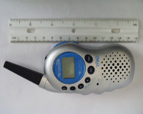
Click to zoom
Application Details
- Equipment Class
- FRF - Part 95 Family Radio Face Held Transmitter
- Date of Grant
- Mar 27, 2003
- Application Purpose
- Original Equipment
- Date of Application
- Mar 27, 2003
- Equipment Note
- GMRS/FRS UHF Transceiver
- Frequency Range
- 467.56250000 - 467.71250000
- Company
- Genex Telecom Co., Ltd.
- Country
- South Korea
Documents & Files
Document Text
Text extracted from the exhibit documents filed with the FCC. Open a document above to read the original.
Users Manual
MK-1996 Basic Operation 03-02-10 1. General Specification - Power On/Off Key : Top - PTT Key : Side [ Tact SW ] - Monitor Key : Side [ Tact SW ] - UP Key : Top - Down Key : Top - SCAN Key : Top - CALL Key : Top - Menu Key : Top - EXT Mic/Speaker Jack[ 3.5ö ] 2. Function Flow Chart F CTCSS PWR Hi/Low DW VOX BEEP Tone Ringer Tone(CALL) F 3. LCD Display 1 of 7 MK-1996 Basic Operation 03-02-10 4. Front, Side, Top Overview 2 of 7 MK-1996 Basic Operation 03-02-10 5. Operating Instruction 1) On/Off & Volume control Switch - Radio ON : Press and hold down the Power[P] button for over 1seconds. All indicators will appear momentarily on the LCD and you will hear short beep sound. - Radio Off : Press and hold down the Power[P] button for over 2seconds until all indicators Disappear on the LCD. - Volume setting : Press up[•£] or down[•¥] button to choose the adjust level that is most Comfortable for you. 2) Setting the Channel MK-1996 has 22 main channels. To select the channel - Turn the radio on - Press up[•£] or down[•¥] button to choose the channel. 3) Setting the Tone Code(CTCSS) MK-1996 has 38 CTCSS Codes To set the Tone Codes(CTCSS) - Press Function[F] button once more,[XX oF up to 38] will appear and tone code digit will blink on the LCD. " oF " means no CTCSS code. - Press up[•£] or down[•¥] button to choose the desired sub-channel to use. - Press the PTT button or Function[F] button to confirm. 4) Setting the Transmit Power HI/LO - HI : 1.6W TX power (ERP) - LO : 500mW TX power To set the TX output power - Press the Function[menu] button until the [ Po LO or HI ] appears. - Press the up[•£] button or down [•¥] button to set the TX power - Press the PTT button or Function[menu] button to confirm. - HI or LO will appear on the LCD. - If the battery is in low condition, the TX Power will be switched to LO automatically. - Even though the TX power is set to HI. 5) Setting the DW(dual watch) and CTCSS in DW mode. To active the DW mode - Press the Function[menu ] button until the [ oF or 1 up to 22] and DW icon blink on the LCD. - Press the up[•£] button or down [•¥] button to choose the channel. - " oF " means no DW mode. 3 of 7 MK-1996 Basic Operation 03-02-10 - Press the PTT button or Function[menu ] button to confirm. - DW icon will appear on the LCD. To stop the dual watch(DW) - Press the "S" Scan button, the unit will stop the dual watch and will return to normal operation and DW icon will disappear from the LCD. - DW icon will disappear from the LCD. 6) VOX (Voice Operated Transmission) This option enables you to have hands-free conversation. You do not have to operate the PTT button each time when you want to transmit. You can also choose the VOX sensitivity to suit your environment of operation. (Ex ; noisy road, motor bike, factory etc.) To set the VOX mode. - Press the Function[menu ] button until the [ Uo oF or x ] appears. x is a vox level - VOX icon will be appeared on the LCD. To set the VOX level - Press the up[•£] button or down [•¥] button to set the VOX level from 1 to 5. "oF" is disable the VOX function. " 3 " is most sensitive. " 1 " is least sensitive. - Press the PTT button or Function[F] button to confirm. 8) Beep tone This feature will give the tone signal to other parties when transmitting finished (when PTT button is released.) To activate or disable the Roger tone - Press the Function[menu ] button until [rb on or oF] and the Roger [ ] icon blink on the LCD. - Press the up[•£] button or down [•¥] button. - Press the PTT button or Function[menu ] button to confirm. 9) Setting the Ringer(CALL) This feature provides 3 user selectable call ringer signal and vibration. To set your favorite call ringer signal. - Press the Function[menu ] button until the [ CA 1 or up to 3 ] appears on the LCD. - Press the up[•£] button or down [•¥] button to select the call melody type. - Press the PTT button to confirm. - To activate the call , click the "PTT" button twice quickly. 4 of 7 MK-1996 Basic Operation 03-02-10 10) Transmitting - Press and hold the PTT button (The "TX" icon bar appears on the LCD) - Speak slowly and clearly - To stop the transmission, release the PTT button - If there are no more receiving signal for 5 seconds, the unit will go into power save 11) Receiving The coding feature reduces the possibility of interference and provides enhanced communication. You can only listen to a call that has correct matching code. Important ; Before transmitting or receiving to the other parties ; - Correct channel is selected ( 1 to 22 ) and - Correct code is set ( 00 to 38 ) 12) Channel Scanning This feature allows you to monitor all activated channels while scanning. To activate the Scan - Press the Scan[S] button - Radio will begin scanning. - When in scan mode, the display will show each scanning channel. - After an activated channel is scanned and received signal and then if there is no more signal, the scan will resume automatically. To disable the Scan - Press the Scan[S] button, the unit will stop the scanning. - SCAN icon indicator will disappear from the LCD - The unit will return to home channel. 13) Call - Press the Call[C] button.( The "TX" icon bar appears on the LCD.) 14) Monitoring the channel It is used for listening the week signal or to hear all activities on the channel by manually overriding channel sub tone code setting. To activate the Monitor feature - Press and hold the Monitor[M] button for over two seconds. - When you hear the sound, release the Monitor[M] button. (The monitor[ ] icon will appear on the LCD.) 5 of 7 MK-1996 Basic Operation 03-02-10 To disable the Monitor feature - Press and hold the Monitor[M] button for over two seconds. (The monitor[ ] icon will disappear on the LCD.) 15) Backlight Backlight is used to improve the display visibility in dark condition. To activate the Backlight - Press and hold the Monitor[M] button in a moment. To disable the Backlight - Press and hold the Monitor[M] button in a moment once again. 16) Keypad Lock The l…
Text truncated - open the document above for the full version.
Users Manual
FCC Information THIS DEVICE COMPLIES WITH PART 15 OF THE FCC RULES. OPERATION IS SUBJECT TO THE FOLLOWING TWO CONDITIONS : (1) THIS DEVICE MAU NOT CAUSE HARMFUL INTERFERENCE, AND (2) THIS DEVICE MUST ACCEPT ANY INTERFERENCE RECEIVED, INCLUDING INTERFERENCE THAT MAY CAUSE UNDERSIRED OPERATION. Safety Information For GMRS UNIT “Important: FCC RF Exposure Requirements: - Operation must not exceed a maximum transmitting duty factor of 50% for satisfying RF exposure compliance. - For body-worn operation, this radio has been tested and meets the FCC RF exposure guidelines when used with GENEX accessories supplied or designated for this product. Use of other accessories may not ensure compliance with FCC RF exposure guidelines. Use only the supplied antenna. Unauthorized antennas, modifications, or attachments could damage the transmitter and may violate FCC regulations. “ Normal Position: Hold the transmitter approximately 1” from your face and speak in a normal voice, with the antenna pointed up and away. GMRS Licensing requirements: The Code of Federal Regulations requires the owner/operator of this equipment to hold a FCC license when operating in the GMRS mode. Operation on the GMRS frequencies is subject to additional rules as specified in 47 CFR Part 95.
Cover Letter(s)
March 22, 2003 Timco Engineering Inc. 849 NW State Road 45 Newberry, FL 32669 Telephone 888.472.2424 Fax 352.472.2030 Applicant: Genex Telecom Co. LTD 6FL Farmax Building 796-27 Bandbae-Dong, Seocho-Gu SEOUL 137-830 SOUTH KOREA FRN 0006-1433-33 Re: Confidentiality of schematics Equipment: GMRS Transceiver FCC ID: PM3 MK1996 Gentlemen: It is requested that the information contained in the block diagrams, operational description, parts list, and schematics of the application be held confidential per Section 0.459. Please use this information in obtaining a grant of certification for the transceiver, for use in the general mobile radio service, model number MK1996. In support of this request, we submit the following: 1. Identification of the specific information for which confidential treatment is sought: The materials set fourth in the Operational Description, Block Diagram, Parts List, and Schematics, are those for which confidentiality is sought. 2. Identification of the Commission proceeding in which the information was submitted or a description of the circumstances giving rise to the submission: The proceeding is that involving the application for equipment authorization (certification) under FCC ID No: PM3 MK1996 3. Explanation of the degree to which the information is commercial or financial, or contains a trade secret or is privileged: This material includes a detailed theory of operation and circuit diagrams, (schematics, part list, and Block diagrams). As such this material is treated as highly confidential business information and is not subject to public view. Should you require any further information, please contact the undersigned. Thank you for your consideration in this matter. Sincerely, Scot Rogers Rogers Labs, Inc. ROGERS LABS, INC. 4405 West 259 th Terrace Louisburg, KS 66053 Phone / Fax (913) 837-3214
Cover Letter(s)
Correspondence Summary Questions and Answers March 27, 2003 SUBJECT: GENEX TELECOM CO., LTD.. - FCC ID: PM3MK1996 TCB Q-6: This device has a jack connector for battery charging with an AC/DC adapter. Please specify if the radio can be operated while charging the batteries. If so, please, provide test data per Part 15.207. Applicant A-2: The AC/DC adapter is used to charge the battery pack when the unit is not transmitting. This same jack is used for the headset. The AC line conducted emissions were reported in the verification report for the receiver since the unit may receive but not transmit with the adapter in use. TIMCO ENGINEERING INC. 849 NW State Road 45 Newberry, Florida 32669 http://www.timcoengr.com 888.472.2424 F 352.472.2030 [email protected]
External Photos
ROGERS LABS, INC. Genex Telecom Co. LTD 4405 W. 259th Terrace MODEL: Mk1996 Louisburg, KS 66053 Test #: 030220 FCCID#: PM3 MK1996 Phone/Fax: (913) 837-3214 Test to: FCC Parts 2 and 95 Page 1 of 2 Mk1996Photos.doc 2/25/2003 Equipment photographs for Mk1996. ROGERS LABS, INC. Genex Telecom Co. LTD 4405 W. 259th Terrace MODEL: Mk1996 Louisburg, KS 66053 Test #: 030220 FCCID#: PM3 MK1996 Phone/Fax: (913) 837-3214 Test to: FCC Parts 2 and 95 Page 2 of 2 Mk1996Photos.doc 2/25/2003
ID Label/Location Info
ROGERS LABS, INC. Genex Telecom Co. LTD 4405 W. 259th Terrace MODEL: MK 1996 Louisburg, KS 66053 Test #: 030220 FCCID#: PM3 MK1996 Phone/Fax: (913) 837-3214 Test to: FCC Parts 2 and 95 Page 1 of 1 MK1996Label.doc 2/25/2003 FCC ID label and location photographs for MK 1996.
Internal Photos
ROGERS LABS, INC. Genex Telecom Co. LTD 4405 W. 259th Terrace MODEL: MK1996 Louisburg, KS 66053 Test #: 030220 FCCID#: PM3 MK1996 Phone/Fax: (913) 837-3214 Test to: FCC Parts 2 and 95 Page 1 of 1 Mk1996IntPho.doc 2/25/2003 Internal photographs of Printed circuit boards for Mk1996.
RF Exposure Info
Test Report S/N: 030303-345PM3 Test Date(s): March 14, 2003 FCC/IC SAR Evaluation © 2003 Celltech Labs Inc.1 of 20 Celltech Labs Inc. declares under its sole responsibility that this device was found to be in compliance with the Specific Absorption Rate (SAR) RF exposure requirements specified in FCC 47 CFR §2.1093 and Health Canada’s Safety Code 6. The device was tested in accordance with the measurement standards and procedures specified in FCC OET Bulletin 65, Supplement C, Edition 01-01 and Industry Canada RSS-102 Issue 1 (Provisional) for the General Population / Uncontrolled Exposure environment. I attest to the accuracy of data. All measurements were performed by me or were made under my supervision and are correct to the best of my knowledge and belief. I assume full responsibility for the completeness of these measurements and vouch for the qualifications of all persons taking them. This test report shall not be reproduced partially, or in full, without the prior written approval of Celltech Labs Inc. The results and statements contained in this report pertain only to the device(s) evaluated. Russell W. Pipe Senior Compliance Technologist Celltech Labs Inc. DECLARATION OF COMPLIANCE SAR EVALUATION Test Lab CELLTECH LABS INC. Testing and Engineering Lab 1955 Moss Court Kelowna, B.C. Canada V1Y 9L3 Phone:250-448-7047 Fax:250-448-7046 e-mail:[email protected] web site:www.celltechlabs.com Applicant Information GENEX TELECOM CO., LTD. 6Fl., Farmax Building 796-27 Bangbae-Dong, Seocho-Gu Seoul, Korea 137-830 Rule Part(s):FCC 47 CFR §2.1093; IC RSS-102 Issue 1 (Provisional) Test Procedure(s):FCC OET Bulletin 65, Supplement C (01-01) Device Type:Portable UHF GMRS PTT Radio Transceiver FCC ID:PM3MK1996 Model(s):MK1996 Modulation:FM (UHF) Tx Frequency Range:462.5625 - 467.7125 MHz (GMRS Channels 15-22) RF Output Power Tested:1.6 Watts (ERP) Antenna Type(s):Fixed Battery Type(s):1.5V AAA Alkaline (x4) 1.2V AAA NiMH (x4) Body-Worn Accessories:Belt-Clip, Ear-Microphone Max. SAR Measured:0.550 W/kg - Face-held (50% Duty Cycle) 0.985 W/kg - Body-worn (50% Duty Cycle) Test Report S/N: 030303-345PM3 Test Date(s): March 14, 2003 FCC/IC SAR Evaluation © 2003 Celltech Labs Inc.2 of 20 TABLE OF CONTENTS 1.0INTRODUCTION..................................................................... 3 2.0DESCRIPTION OF EUT............................................................ 3 3.0SAR MEASUREMENT SYSTEM ............................................... 4 4.0MEASUREMENT SUMMARY..................................................... 5 5.0DETAILS OF SAR EVALUATION............................................... 6 6.0EVALUATION PROCEDURES................................................... 6 7.0SYSTEM PERFORMANCE CHECK........................................ 7 8.0SIMULATED TISSUES............................................................. 8 9.0SAR LIMITS........................................................................... 8 10.0SYSTEM SPECIFICATIONS...................................................... 9 11.0PROBE SPECIFICATION.........................................................10 12.0SAM PHANTOM......................................................................10 13.0VALIDATION PHANTOM...........................................................10 14.0DEVICE HOLDER....................................................................10 15.0TEST EQUIPMENT LIST...........................................................11 16.0MEASUREMENT UNCERTAINTIES............................................12 17.0REFERENCES.......................................................................13 APPENDIX A - SAR MEASUREMENT DATA.............................................14 APPENDIX B - SYSTEM CHECK DATA....................................................15 APPENDIX C - SYSTEM VALIDATION.....................................................16 APPENDIX D - PROBE CALIBRATION....................................................17 APPENDIX E - MEASURED FLUID DIELECTRIC PARAMETERS................18 APPENDIX F - SAM PHANTOM CERTIFICATE OF CONFORMITY..............19 APPENDIX G - SAR TEST SETUP & EUT PHOTOGRAPHS........................20 Test Report S/N: 030303-345PM3 Test Date(s): March 14, 2003 FCC/IC SAR Evaluation © 2003 Celltech Labs Inc.Genex Telecom Co., Ltd. FCC ID: PM3MK1996 (Model: MK1996)3 of 20 Portable UHF GMRS PTT Radio Transceiver (462.5625-467.7125MHz) 1.0 INTRODUCTION This measurement report demonstrates compliance of the Genex Telecom Co., Ltd. Model: MK1996 Portable UHF GMRS PTT Radio Transceiver FCC ID: PM3MK1996 with the RF exposure requirements of FCC 47 CFR §2.1093 (see reference [1]), and Health Canada’s Safety Code 6 (see reference [2]) for the General Population / Uncontrolled Exposure environment. The test procedures described in FCC OET Bulletin 65, Supplement C, Edition 01-01 (see reference [3]) and IC RSS-102 Issue 1 (Provisional) (see reference [4]), were employed. A description of the product, operating configuration, detailed summary of the test results, methodology and procedures used in the evaluation, equipment used, and the various provisions of the rules are included within this test report. 2.0 DESCRIPTION of Equipment Under Test (EUT) FCC Rule Part(s) 47 CFR §2.1093 IC Rule Part(s) RSS-102 Issue 1 (Provisional) Test Procedure(s) FCC OET Bulletin 65, Supplement C (01-01) Device Type Portable UHF GMRS PTT Radio Transceiver FCC ID PM3MK1996 Model(s) MK1996 Serial No. Pre-production Modulation FM (UHF) Tx Frequency Range 462.5625 - 462.7125 MHz (GMRS Channels 15-22) RF Output Power Tested 1.6 Watts (ERP) Battery Type(s) 1.5V AAA Alkaline (x4) 1.2V AAA NiMH (x4) Antenna Type(s) Fixed Body-Worn Accessories Tested Belt-Clip, Ear-Microphone Test Report S/N: 030303-345PM3 Test Date(s): March 14, 2003 FCC/IC SAR Evaluation © 2003 Celltech Labs Inc.Genex Telecom Co., Ltd. FCC ID: PM3MK1996 (Model: MK1996)4 of 20 Portable UHF GMRS PTT Radio Transceiver (462.5625-467.7125MHz) 3.0 SAR MEASUREMENT …
Text truncated - open the document above for the full version.
Test Report
TEST REPORT For APPLICATION of CERTIFICATION For Genex Telecom Co. LTD 6FL Farmax Building 796-27 Bandbae-Dong, Seocho-Gu SEOUL 137-830 SOUTH KOREA Clark Cheon Manager MODEL: MK 1996 General Mobile Radio Services (GMRS) UHF TRANSCEIVER FREQUENCY: 462 - 467 MHz FCC ID: PM3 MK1996 Test Date: February 20, 2003 Certifying Engineer: Scot D. Rogers ROGERS LABS, INC. 4405 West 259th Terrace Louisburg, KS 66053 Phone: (913) 837-3214 FAX: (913) 837-3214 This report shall not be reproduced except in full, without the written approval of the laboratory. This report must not be used by the client to claim product endorsement by NVLAP or any agency of the U.S. Government. ROGERS LABS, INC. 4405 West 259 th Terrace Louisburg, KS 66053 Phone / Fax (913) 837-3214 NVLAP Accredited Laboratory NVLAP Lab Code: 200087-0 ROGERS LABS, INC. Genex Telecom Co. LTD 4405 West 259 th Terrace MODEL: MK 1996 GMRS UHF Transceiver Louisburg, KS 66053 Test #:030220 FCC ID#: PM3 MK1996 SN: Set 1 Phone/Fax: (913) 837-3214 Test to: FCC Parts 2, 15, and 95 Page 2 of 22 CERTIFICATION\MK1996TstRpt 03/26/2003 TABLE OF CONTENTS FORWARD: 3 LIST OF TEST EQUIPMENT 3 2.1033(C) APPLICATION FOR CERTIFICATION 4 2.1046 RF POWER OUTPUT 5 Measurements Required: 5 Test Arrangement: 5 Results: 5 2.1047 MODULATION CHARACTERISTICS 6 Measurements Required: 6 Test Arrangement: 7 Results: 7 2.1049 OCCUPIED BANDWIDTH 9 Measurements Required: 9 Test Arrangement: 9 Results: 9 2.1051 SPURIOUS EMISSIONS AT ANTENNA TERMINALS 11 Measurements Required: 11 Test Arrangement: 11 Results: 13 2.1053 FIELD STRENGTH OF SPURIOUS RADIATION 13 Measurements Required: 13 Test Arrangement: 13 Results: 15 2.1055 FREQUENCY STABILITY 16 Measurements Required: 16 Test Arrangement: 16 Results: 18 APPENDIX 19 NVLAP Accredited Laboratory NVLAP Lab Code: 200087-0 ROGERS LABS, INC. Genex Telecom Co. LTD 4405 West 259 th Terrace MODEL: MK 1996 GMRS UHF Transceiver Louisburg, KS 66053 Test #:030220 FCC ID#: PM3 MK1996 SN: Set 1 Phone/Fax: (913) 837-3214 Test to: FCC Parts 2, 15, and 95 Page 3 of 22 CERTIFICATION\MK1996TstRpt 03/26/2003 FORWARD: In accordance with the Federal Communications Code of Federal Regulations, dated October 1, 2001, Part 2 Subpart J, Paragraphs 2.907, 2.911, 2.913, 2.915, 2.925, 2.926, 2.1031 through 2.1057, applicable paragraphs of Parts 15, and 95, the following is submitted: List of Test Equipment A Hewlett Packard 8591EM and or 8562A Spectrum Analyzer was used as the measuring device for the emissions testing. The analyzer settings used are described in the following table. Refer to the Appendix for a complete list of Test Equipment. HP 8591EM SPECTRUM ANALYZER SETTINGS CONDUCTED EMISSIONS: RBW AVG. BW DETECTOR FUNCTION 9 kHz 30 kHz Peak/Quasi Peak RADIATED EMISSIONS (30 – 1000 MHz): RBW AVG. BW DETECTOR FUNCTION 120 kHz 300 kHz Peak/Quasi Peak HP 8562A SPECTRUM ANALYZER SETTINGS RADIATED EMISSIONS (1 – 40 GHz): RBW AVG. BW DETECTOR FUNCTION 1 MHz 1 MHz Peak/Average ANTENNA CONDUCTED EMISSIONS: RBW AVG. BW DETECTOR FUNCTION 120 kHz 300 kHz Peak NVLAP Accredited Laboratory NVLAP Lab Code: 200087-0 ROGERS LABS, INC. Genex Telecom Co. LTD 4405 West 259 th Terrace MODEL: MK 1996 GMRS UHF Transceiver Louisburg, KS 66053 Test #:030220 FCC ID#: PM3 MK1996 SN: Set 1 Phone/Fax: (913) 837-3214 Test to: FCC Parts 2, 15, and 95 Page 4 of 22 CERTIFICATION\MK1996TstRpt 03/26/2003 2.1033(c) Application for Certification (1) Manufacturer: Genex Telecom Co. LTD 6FL Farmax Building 796-27 Bandbae-Dong, Seocho-Gu SEOUL 137-830 SOUTH KOREA (2) Identification: Model: MK 1996 S/N: Set 1 FCC I.D.: PM3 MK1996 (3) Instruction Book: Refer to exhibit for Draft Instruction Manual. (4) Emission Type: 7K0F3E (5) Frequency Range: 462 and 467 MHz (6) Operating Power Level: 1.6 Watts (High Power) 0.5 Watts (Low Power) (7) Max P o : 1.6 Watts (8) Power into final amplifier: 1.6 Watt Unit: 4.80 Watts (6.0V @ 0.8A) (9) Tune Up Procedure for Output Power: Refer to Exhibit for Transceiver Alignment Procedure. (10) Circuit Diagrams; description of circuits, frequency stability, spurious suppression, and power and modulation limiting: Refer to Exhibit for Circuit Diagrams. Refer to Exhibit for Theory of Operation. (11) Photograph or drawing of the Identification Plate: Refer to Exhibit for Photograph or Drawing. (12) Drawings of Construction and Layout: Refer to Exhibit for Drawings of Components Layout and Chassis Drawings. (13) Detail Description of Digital Modulation: Not applicable. NVLAP Accredited Laboratory NVLAP Lab Code: 200087-0 ROGERS LABS, INC. Genex Telecom Co. LTD 4405 West 259 th Terrace MODEL: MK 1996 GMRS UHF Transceiver Louisburg, KS 66053 Test #:030220 FCC ID#: PM3 MK1996 SN: Set 1 Phone/Fax: (913) 837-3214 Test to: FCC Parts 2, 15, and 95 Page 5 of 22 CERTIFICATION\MK1996TstRpt 03/26/2003 2.1046 RF Power Output Measurements Required: Measurements shall be made to establish the radio frequency power delivered by the transmitter into the standard output termination. The power output shall be monitored and recorded and no adjustment shall be made to the transmitter after the test has begun, except as noted below: If the power output is adjustable, measurements shall be made for the highest and lowest power levels. Test Arrangement: The radio frequency power output was measured at the antenna terminal by replacing the antenna with a spectrum analyzer and appropriate attenuation. The spectrum analyzer had an impedance of 50W to match the impedance of the standard antenna. A HP 8591EM Spectrum Analyzer was used to measure the radio frequency power at the antenna port. The data was taken in dBm and converted to watts as shown in the following Table. Data was taken per Paragraph 2.1046(a) and applicable parts of Parts 2 and 95. P dBm = power in dB above 1 milliwatt. Milliwatts = 10 (PdBm/10) Watts = (Milliwatts)x(0.001)(W/mW) 31.90 dBm = 10 (31.90/10) 26.77 dBm = 10 (26.77/10) = 1,550.0 mW = 475.34 mW = 1.6 Watts = 0.5 Watts Results: FREQUENCY P dBm P mw P w 462.5625 31.90 1,…
Text truncated - open the document above for the full version.
Test Setup Photos
ROGERS LABS, INC. Genex Telecom Co. LTD 4405 W. 259th Terrace MODEL: MK1996 Louisburg, KS 66053 Test #: 030220 FCCID#: PM3 MK1996 Phone/Fax: (913) 837-3214 Test to: FCC Parts 2 and 95 Page 1 of 1 MK1996TstPhot.doc 2/25/2003 Test setup photographs for Mk1996.
Contact Information
Applicant
Clark Cheon(Manager)
Test Firm
Rogers Labs, Inc.Scot Rogers
Technical Specifications
| # | Rule Parts | Frequency Range | Power Output | Emission | Tolerance |
|---|---|---|---|---|---|
| 3 | 95B | 467.5625 MHz - 467.7125 MHz | 500.00 mW | 12K0F3E | 2.5 ppm |
Other Applications from Genex Telecom Co., Ltd.
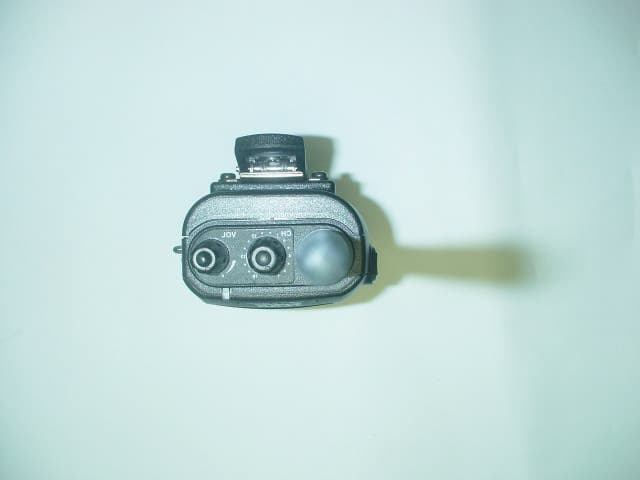
PM3GT40
Dec 08, 2004UHF LMRS TRANSMITTER
Equipment Class
TNF - Licensed Non-Broadcast Transmitter Held to Face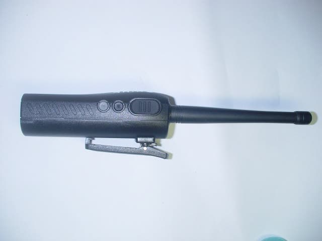
PM3GT10
Dec 08, 2004UHF LMRS TRANSMITTER
Equipment Class
TNF - Licensed Non-Broadcast Transmitter Held to Face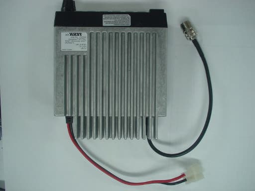
PM3MT900
Nov 28, 2004LAND MOBILE RADIO SERVICE GMRS TRANSMITTER
Equipment Class
TNB - Licensed Non-Broadcast Station Transmitter
PM3GR5500
Jul 18, 2004GMRS/FRS UHF Transceiver
Equipment Class
FRF - Part 95 Family Radio Face Held Transmitter
PM3GX80
Jul 01, 2004Transceiver, VHF, PTT
Equipment Class
TNF - Licensed Non-Broadcast Transmitter Held to Face