PM8PM-9900Gaming Table Management System - PC Station
AL Tech, Inc.
Click to zoom
Application Details
- Equipment Class
- TNB - Licensed Non-Broadcast Station Transmitter
- Date of Grant
- Nov 14, 2001
- Application Purpose
- Original Equipment
- Date of Application
- Nov 14, 2001
- Equipment Note
- Gaming Table Management System - PC Station
- Frequency Range
- 451.18750000 - 451.18750000
- Company
- AL Tech, Inc.
- Country
- South Korea
Documents & Files
Document Text
Text extracted from the exhibit documents filed with the FCC. Open a document above to read the original.
Users Manual
Users’ manual GAMING TABLE MANAGEMENT SYSTEM (GTMS) Contents Caution Chapter 1 Introduction Overview Product Description Checklist Drawing of Modules Chapter 2 Installation Drawing of interconnection Chapter 3 Operation Technical Specifications Caution Circuit devices are sensitive to static electricity, which can damage their delicate electronics. Dry weather conditions or walking across a carpeted floor may cause you to acquire a static electrical charge. To protect your device, always l Touch the metal chassis of your computer before you pick up the circuit device. This grounds the static electrical charge. l Pick up the device by holding it on the left and right edges only. Chapter 1 Introduction Overview For a gaming business, the competitive edge depends on how you manage information. The GAMING TABLE MANAGEMENT SYSTEM(GTMS) is a data gathering system that communicate with Personal Computer(PC). From these data, you can manage gaming table. Product Description The GTMS has the following two sub-modules. l Table Module (TM) TM is installed in gaming table. When dealer or customer press the key, TM sends key data to PC Module (PM) via wireless connection. l PC Module (PM) PM is installed in management table. It is connected to PC with RS-232C cable. PM gather the data from TM and relay it to PC. Checklist The GTMS should contain the following items. l 1 TM l 1 PM l 1 Battery l 1 Power adaptor for PM l 1 RS-232C serial cable l 1 Floppy Disk l 1 Battery cable Drawing of Modules 1. TM 2. PM Chapter 2 Installation Please follow these steps to install GTMS: 1. Verify that voltage of AC power supply is correct before plugging in power cable 2. Attach one end of the serial cable to the RS-232C port on the computer, and the other end to PM port. 3. Copy PC program “com-test.exe” from floppy disk to PC. 4. Power on PM with power adaptor. RS-232C 5. Power on TM with battery. 6. Execute com-test.exe on Window 95/98 operation system (O/S). 7. Select com port that is connected with PM. 8. Check Hex menu. 9. Click Port Set Chapter 3 Operation When keys in TM are pressed, key data are displayed on PC program. key key data power on 79 04 00 00 00 00 7d 4 79 04 00 00 12 01 01 6f or 79 04 00 00 92 01 01 ef 5 79 04 00 00 12 01 20 4e or 79 04 00 00 92 01 20 ce 7 79 04 00 00 12 01 08 66 or 79 04 00 00 92 01 08 e6 8 79 04 00 00 12 01 02 6c or 79 04 00 00 92 01 02 ec 9 79 04 00 00 12 01 10 7e or 79 04 00 00 92 01 10 fe Note: When the key 1,2, or 3 is pushed without dropped chip(s), then it make a beep to notice that it is a wrong sequence. After a chip is dropped, a led flickers for about 10 seconds, key 1, 2, or 3 should be pushed during this time. The led stops flickering when a key is pushed, or if any key is not pushed until 10 seconds expire, then it makes a beep to notice that keys are not pushed. Technical Specifications Features of connector: RS-232C connector for serical communication with PC 1 2 3 4 5 6 7 8 9 Wireless Transfer Rate : 1Kbps (kilobits per second) RS-232C Trnasfer Rate: 9600bps (bits per second) AC Line Voltage : 110/240 ~ AC DC 7.5V Frequency 50/60 Hz Battery Voltage : DC 7.5V Caution: Changes or modifications not expressly approved by the manufacturer responsible for compliance could void the user’s authority to operate the equipment. Information to User: This equipment has been tested and found to comply with the limits of a Class B digital device, pursuant to Part 15 of the FCC Rules. These limits are designed to provide reasonable protection against harmful interference in a residential installation. This equipment generates, uses and can radiate radio frequency energy and, if not installed and used in accordance with the instruction, may cause harmful interference to radio communications. However, there is no guarantee that interference will not occur in a particular installation; if this equipment does cause harmful interference to radio or television reception, which can be determined by turning the equipment off and on, the user is encouraged to try to correct the interference by one or more of the following measures: 1. Reorient / Relocate the receiving antenna. 2. Increase the separation between the equipment receiver 3. Connect the equipment into an outlet on a circuit difference from that to which the receiver is connected. 4. Consult the dealer or an experienced radio/TV technician for help. “Importance Notice To comply with FCC RF exposure compliance requirements, the following antenna installation and device operating configuration must be satisfied: - Do not alter or modify the antenna. - Only use the antenna(s) that are originally installed on the device. - A separation distance of at least 20 cm must be maintained between the antenna of this device and all persons.”
Block Diagram
RF (451.1875MHz) •BATTERY RF TRANSCEIVER DC Regulator •TO CARD READER •BUTTONS Project-G 01/20/00 Overall PLT2.0 TM-9900 P03J.Y. KimALT ConfidentialALT Confidential •TO CHIP SENSOR •The battery type is selected to provide power to the device for six months. •To save power, manually sliding magnetic card reader is used. •A micro-switch is used to detect a chip drop. •MAC protocol will be developed such that minimum power consumption is also considered. •MAC will handle data collision. •The CPU with A/D, I/O ports, RAM and ROM will be used. CPU PIC16C73A*/63A RF TRANSCEIVER MODULE RB4 +5V /MCLR 20pF 4.00MHz OSC1 OSC2 *PIC16C73A: 28pins, 4KW codes, 22 io RF (451.1875MHz) ALT ConfidentialALT Confidential Project-G 04/26/00 Block diagram PLT2.0 TM-9900P04J.Y. Kim /Vtx Tx Vrx Rx +V RA1 RC0 RA2 RC1/2 RA0 RB5 Data i/f (Card reader) RC5 RB0 RC4 Call SVC LED RA3 Service Calls (Int.) (Int.) (Int.) RB1 RB2 RB3 43 12C (Int.) RC6 RC7 1: Chip delivery 2: Food service 3: Floor person 4: Open seating C: Cancel L: Log in/out RC3 L RB6 $3 $2 $1 (Int.) RB7 MICRO SWITCH Battery (+9.0V) 5V Reg. +5V 3V Reg. 1 2 3 4 5 CDP RDD RCP +5 Buzzer ALT ConfidentialALT Confidential Project-G 04/26/00 RF transceiver RF Module P05J.Y. Kim PLT2.0 RF power amplifier OSC RF Switch 1stIF2ndIF Narrow FM Demodulator 1stLo OSC2ndLo OSC Txdata Rx data Antenna RF transceiver CNT2 CNT1 1 6 12 7 TRXNF4 Top view of Automan RF module connector1 (CNT1) pin 1 : GND pin 2 :TxData (Tx) pin 3 :TxPower1 (Vtx1) pin 4 : Tx Power2 (Vtx2) pin 5 : Carrier Sense pin 6 : Antenna (ANT) Vtx 1.5 -5.0V connector2 (CNT2) pin 12 : GND pin 11 : Rx Power ctrl(BS) pin 10 : Rx data (Rx) pin 9 : NC (AF) pin 8 : Rx Power (Vrx) pin 7 : NC (AL) Rx open collector out (10K pull-up). Vrx 1.5 -4.0V ALT ConfidentialALT Confidential -GTMS Revenue -GTMS Guest’s Comp TM#1TM#m Table A24 calls food service. Table B30 calls a floorperson. Table A12 needs a new battery The Table Module(TM) •••• Project-G 04/26/00 Overall PLT2.0 Protocols P06J.Y. Kim WD#1WD#k The Wand(WD) •••• -GTMS Service Call PM PM Project-G 01/29/00 Protocol-Revenue PLT2.0 Protocols P07J.Y. Kim ALT ConfidentialALT Confidential PM TM#1 WD#k GTMS Revenue •PC Module is a master and Table Modules are slaves. •Collision may happen due to multiple TM’s. •CA (collision avoidance) is needed. •TM sends a packet first, then TM waits for con- firm packet from the PM. •If confirm packet doesn’t arrive for predefined time, collision happened. •GTMS Revenue PC s/w downloads TM & WD id table and a list of [appl], here this is {0x11, 0x12} From TM to PM: From PM to TM: MAC format [tm0]..[tm2][cmd][lng][d0]..[dn][chk] [tm0]..[tm2] 23 bits with b7 of tm0=0 [cmd] 0x11 for TM, 0x12 for Wand [lng] length of application packet PHY format <Preamble><SIF><MAC data> PHY format <Preamble><SIF><MAC data> MAC format [tm0]..[tm2][cmd][0][chk] Preamble = 0011001100110001 = 0x3331 • • TM#m Project-G 04/26/99 Protocol-Service Call PLT2.0 Protocols P07aJ.Y. Kim ALT ConfidentialALT Confidential TM#1 TM#m GTMS Service Call •PM receives call service information. •PM responds by sending confirm packet. •Collision may happen due to multiple TM’s. •CA (collision avoidance) is needed. •TM sends a packet first, then TM waits for con- firm packet from the PM. •If confirm packet doesn’t arrive for predefined time, collision happened. •GTMS Service Call PC s/w downloads TM id table and a list of [appl], here this is {0x12} •PM supports ‘Simple Display’mode where dummy terminal or LED display can be used. DATA: 0x1 : Chip delivery 0x2 : Food service 0x4 : Change battery 0x8 : Open seating 0x10: Cancel 0x20 : Floor person call From TM to PM: From PM to TM: MAC format [tm0]..[tm2][cmd][1][data][chk] [tm0]..[tm2] 23 bits with b7 of tm0=0 [cmd] 0x12 for GTMS Service Call [lng=1] length of application packet PHY format <Preamble><SIF><MAC data> PHY format <Preamble><SIF><MAC data> MAC format [tm0]..[tm2][cmd][0x0][chk] PM • • • OR H1 -Food ALT ConfidentialALT Confidential Project-G PIC16C76A Battery (+3.0V) RF TRANSCEIVER MODULE +5V /MCLR 20pF 4.00MHz OSC1 OSC2 *PIC16C76A: 28pins, 8KW codes,368RAM, 22 io RF (451.1875MHz) ALT ConfidentialALT Confidential SCL SDA /Vtx Tx Vrx Rx Cs +V RB6 RC0 RB7 RC1/RC2 RA0 RA1 RA3 RC4 RB0 RB1 RB2 RB3 (Int.) RA2 RA4 RA5 RC6 RC7(int.) USART Rx USART Tx DDC +3V RC3 I C 2 Project-R 09/27/99 DataCollectorHardware V.10 PM-9900P03aJ.Y. Kim +5V JP1 -JP3 (ssp address) LED RB4 RB5 RC5 JP6 (encoding) JP4 -JP5 (reserved) 24LC64 EEPROM {BASE} {CH1,CH2,CH3,CH4,CH5} {BASE}
Cover Letter(s)
Dear Mike, Q1. conducted power -1.57, ERP -14.7dBm Answer: Our recheck revealed that The measured low ERP is due to bad connection between the antenna and the circuit board. we re-do the soldering and the measured ERP is -5.6 dBm. The new revised report would be uploaded shortly. Q2. 6.6dBi antenna gain in ERP calculation Answer: 6.6 dBi is due to the fact that we use the log antenna for substituting Tx ant instead of stantard dipole. The new ERP measurement used the stardard dipole and would not have this factor in the calculation. Best Regards, Steve Cheng EMC Engineering Manager Compliance Certification Services 561 F Monterey Road Morgan Hill, CA95037-9001 Phone: (408) 463-0885 ext. 119 Fax: (408) 463-0888 E-Mail: [email protected] -----Original Message----- From: Mike Kuo Sent: Monday, November 12, 2001 1:10 PM To: Steve Cheng Cc: Denise Teng; Anne Liang Subject: FW: AL TECH, INC., FCC ID:PM8PM-9900, Assessment no:AN01T1338 -----Original Message----- From: CERTADM Sent: Monday, November 12, 2001 1:06 PM To: '[email protected]' Subject: AL TECH, INC., FCC ID:PM8PM-9900, Assessment no:AN01T1338 Notice_content ------------- Question #1: Page 11 of test report listed the antenna conducted output power is -1.57dBm. However, as indicated in the ERP measuremnt on page 14 of test report is -14.7dBm. Please explain the difference in these measurement. In addition, as indicated in page 12 of test report, during subsitution tests, dipole antenna was used. However, the calculated ERP measurement with antenna gain of 6.6dBi antenna gain. Please explain. Best Regards Mike Kuo / TCB Certifier The items indicated above must be submitted before processing can continue on the above referenced application. Failure to provide the requested information within 60 days of the original e-mail date may result in application dismissal and forfeiture of the filing fee. Also, please note that partial responses increase processing time and should not be submitted. Any questions about the content of this correspondence should be directed to the e-mail address listed below the name of the sender. From: Denise Teng Sent: Tuesday, November 06, 2001 1:12 PM To: Mike Kuo Cc: Anne Liang Subject: RE: Al Tech FCC ID:PM8PM-9900 Assessment no:AN01T1338 Hi Mike, Please see attachments for the answers. Thanks! regards. -----Original Message----- From: Mike Kuo Sent: Friday, October 19, 2001 5:20 PM To: Anne Liang; Denise Teng Subject: Al Tech FCC ID:PM8PM-9900 Assessment no:AN01T1338 Question #1: Please provide Tune-UP Procedure per 2.1033((c)(9) of FCC rules. Please note : Tune-up procedure is the procedure that use by the manufacturer to make sure the output power and frequency range are within the specification. Question #2: Please provide Parts list. Question #3: There is no user information and RF exposure information are included. Since this device is capable of connecting to Personal Computer. 15.21 , 15.105(b) and the following RF exposure information. Suggested RF exposure statement to be included in the user manual: " Importance Notice To comply with FCC RF exposure compliance requirements, the following antenna installation and device operating configuration must be satisfied: - Do no alter or modify the antennas. - Only use the antenna(s) that are originally installed on the device. - A separation distance of at least 20 cm must be maintained between the antenna of this device and all persons." Question #4: Please provide MPE calculation. Question #5: Please provide Emission Designator and justify by using Carson rules ( 2m+2dk) Best Regards ========================= Mike Kuo Compliance Certification Services 561F Monterey Road Morgan Hill CA 95037 Telephone number:408-463-0885 EXT:105 Fax number :408-463-0888 E-Mail:[email protected]
ID Label/Location Info
PROPOSED FCC ID LABEL AND LOCATION AL Tech, Inc. This device complies with Part 90 of the FCC Rules. FCC ID: PM8PM-9900 FCC ID LABEL LOCATION
Operational Description
Operational Description GAMING TABLE MANAGEMENT SYSTEM (GTMS) AL Tech, Inc. Woonjae Bldg. 2F 1534-1 Seocho-3Dong Seocho-Gu, Seoul, Korea 137-073 Contents CHAPTER 1 DESCRIPTION OF HOW THE DEVICE WORKS........................................................ 3 CHAPTER 2 NECESSARY BANDWIDTH CALCULATION.............................................................. 5 CHAPTER 3 DESCRIPTION OF EMISSION DESIGNATOR AND TYPE O F MODULATION.... 5 CHAPTER 4 DESCRIPTION OF CIRCUITRY REQUIRED BY 2.1033(B)(4).................................. 7 Chapter 1 Description of how the device works. Product Description The GTMS is composed of one PM and many TMs as described in the following:. ! Table Module (TM) TM is installed on a gaming table. When a dealer pushed a key or other information is ready to go, the TM sends data to a PC Module (PM) via wireless connection. ! PC Module (PM) PM is installed in a management room. It is connected to a PC with RS-232C cable. The PM gathers data from TM’s and uploads them to the PC. Drawing of Modules 1. TM 2. PM Description of operation - The TM on each gaming table collects two types of information; revenue-related data and service calls. The revenue data include the dealer’s I.D., number of hands processed for a certain period by the dealer and amount of chips collected by the dealer. There are two packets defined for these events: 1. A packet that is transmitted when a dealer comes in to a table by sliding his or her I.D. card through the TM. The packet includes only a dealer I.D. 2. A packet that is transmitted when a dealer leaves the table by sliding his or her I.D. card through the TM. The packet includes a dealer I.D., number of hands handled by the dealer, amount of chips collected by the dealer. The other type of information, service calls, is a third type of packet that is transmitted whenever a dealer pushed a service call button. Currently five buttons are supported. Typical example of services is: ‘Chip Exchange Request’, ‘Food Request’, ‘Seat Open’, ‘Floor person Call’, and ‘Cancel’. Each TM has its own network address that is three bytes long and is included in the packet so that the TM sends a packet including this network address or MAC (Medium Access Control) address. When the PM receives a packet from a TM, it reads TM’s MAC address and check if it is on the registration list. It discards the packet whose MAC address is not in the registration list. The PC GTMS software downloads a table of TM MAC addresses to the PM at the initialization of the software that comes with the GTMS. The PC software also provides registration of TMs, registration of dealers, and revenue management functions. From a network configuration perspective, the GTMS system is an N-to-1 system. There are N TM’s that send packets independently to the PM. In case there happens a data collision that is inevitable in any LAN, retrial of transmission is done by a similar rule defined in IEEE802.11 standard. The TM uses a single carrier frequency, 451.1875MHz, and narrow-band FSK modulation is used. The encoding we used guarantees that DC level is zero. Symbol rate is 1kbps, though bit rates varies from 1kbps to 2kbps. One PM can have up to two RF channels for maximum capacity. The two RF channels may use the same or different carrier frequency. Each channel can handle 80 TM’s so total of 160 TM’s can be handled by one PM. Chapter 2 Necessary Bandwidth Calculation From the graph below, we obtained the bandwidths as follows: - Bandwidth of data swing: 4kbps - Bandwidth of carrier frequency including noise at 73dB down from peak : 25kbps Chapter 3 Description of emission designator and type of modulation Chapter 4 Description of circuitry required by 2.1033(b)(4) (Refer Chapter 1. Additional description of the ground system and antenna is included here) The following figure shows how the antenna is connected to the PCB (PM). The ground is connected to the steel case so that unnecessary radiation is minimized.
Parts List/Tune Up Info
1. Tune up Procedure over the Frequency Range. As the picture shows, we use spectrum analyzer for frequency check. To make sure that the module should not be working out of range even after it is installed in the field, there is no tuning potentiometer on the module. That is, every module is checked in the manufacturing line and the module which operates out of specified frequency range is dropped as failed module. 2. Tune up Procedure over the Power Range. As the picture shows, we use RF power meter for power level check. To make sure that the module should not be working out of range even after it is installed in the field, there is no tuning potentiometer on the module. That is, every module is checked in the manufacturing line and the module which operates out of specified power level range is dropped as failed module.
Parts List/Tune Up Info
PMpartlist Revised: Thursday, October 25, 2001 Revision: Bill Of Materials October 25,2001 11:30:23 Page1 Item Quantity Reference Part ______________________________________________ 1 4 C1,C2,C27,C28 5P 2 6 C3,C13,C16,C39,C43,C44 10u/16V 3 1 C4 47u/16V 4 19 C5,C6,C12,C14,C15,C17, 0.1u C18,C19,C20,C22,C23,C25, C26,C35,C38,C40,C41,C45, C46 5 2 C29,C7 3P 6 2 C30,C8 10P 7 5 C9,C10,C31,C36,C37 103P 8 2 C34,C11 100u/16V 9 6 C21,C24,C32,C33,C42,C47 20p 10 6 D1,D3,D5,D7,D9,D11 Yellow 11 6 D2,D4,D6,D8,D10,D12 Green 12 2 F2,F1 SAW FILTER 13 1 JP1 DC 9V 14 2 J1,J2 ANT 15 1 J3 CON8 16 4 L1,L2,L6,L7 Bead 17 4 L3,L8,L9,L12 33nH 18 2 L4,L10 27nH 19 2 L5,L11 15nH 20 1 P1 Male DB9 21 2 Q1,Q2 2N2907 22 1 RT1 THERMISTOR 10K 23 2 R3,R1 21 24 4 R2,R8,R31,R40 50 25 2 R4,R39 100K 26 1 R5 10 27 2 R15,R6 47 28 2 R7,R38 29 Page 1 PMpartlist 29 14 R9,R16,R21,R22,R26,R30, 330 R32,R34,R37,R47,R56,R57, R61,R66 30 2 R48,R10 470 31 2 R51,R11 2K 32 2 R12,R53 5.6K 33 2 R54,R13 3K 34 2 R14,R55 2.2K 35 23 R17,R18,R19,R20,R23,R29, 4.7K R35,R36,R42,R43,R44,R45, R46,R49,R50,R52,R58,R59, R60,R62,R63,R64,R65 36 1 R24 30K 37 2 R28,R25 10K 38 1 R27 1.2K 39 2 R41,R33 1 40 2 S1,S3 tset mode(TX STOPPING) 41 3 S2,S4,S6 SW DIP-8 42 1 S5 SW DIP-4 43 1 U1 LM7805 44 2 U8,U2 TRFX 45 1 U3 LM7803 46 3 U4,U7,U9 PIC16C76 47 1 U5 MAX232 48 1 U6 LM393 49 1 U10 24C32A 50 3 Y1,Y2,Y3 4MHz Page 2
RF Exposure Info
M PE CALCULATION for PM - 9900 Formular used in the MPE Calculations: E^2/3770 = S, mW/cm2 Pwatts*Ggain = 10^(PdBm-30+GdBi)/10) E, V/m = (Pwatts*Ggain*30)^.5/d, meters d = ((Pwatts*G*30)/3770*S))^0.5 --------- (A) Since S (mW/cm 2 ) =0.30 from 1.1310 Table 1 P (dBm) =-14.7EUT output power G (dBi) =0.0EUT antenna gain Substitute these parameters into the A above, we have MPE safe distance d (cm) = 0.1 NOTE: For mobile or fixed location transmitters, minimum separation distance is 20 cm, even if calculations indicate MPEdistanceisless
Schematics
A A B B C C D D E E 44 33 22 11 1001_01 Data Sender for the GTMS C 1Wednesday, December 20, 2000 1.0 Title SizeDocument NumberRev Date:Sheetof U5 MAX232 V+ 2 T1IN 11 T2IN 10 GND 15 T2OUT 7 T1OUT 14 R1IN 13 Vcc 16 R1OUT 12 R2OUT 9 C1+ 1 C1- 3 V- 6 R2IN 8 C2+ 4 C2- 5 C21 0.1u 3K R11 21 R1 2K R46 C31 20p R28 50 C38 0.1u C6 0.1u 330 R29 R7 330 330 R23 C28 3P C19 0.1u C15 0.1u D7 Yellow L3 33nH D8 Green R41 330 R31 4.7K C7 3P 2K R8 D10 Green C14 0.1u 330 R19 C26 5P R32 4.7K C12 10u/16V + 330 R27 R2 50 4.7K R55 D1 Yellow R12 47 D12 Green 3K R48 J1 ANT D3 Yellow 3K R47 330 R54 D5 Yellow 2K R44 S4 SW DIP-8 1 2 3 4 8 7 6 5 330 R49 4.7K R40 F1SAW FILTER 13 S F2SAW FILTER 13 S 4.7K R17 U8 TRFX GND 1 Tx 2 AL 12 GND 7 BS 8 VTx1 3 VTx2 4 RSSI 5 ANT 6 FSK Out 9 AF 10 VRx 11 R26 4.7K D9 Yellow L8 33nH C13 0.1u C18 0.1u C43 0.1u R20 4.7K C2 5P Q1 2N2907 3 2 1 P1 Male DB9 5 9 4 8 3 7 2 6 1 C10 103P C41 10u/16V + 330 R30 C9 103P 4.7K R16 D2 Green L2Bead 4.7K R39 4.7K R15 C33 0.1u J3 CON8 1 2 3 4 5 6 7 8 4.7K R38 U6A LM393 3 2 1 8 4 + - 4.7K R14 D4 Green RT1 THERMISTOR 10K t R52 4.7K L6Bead 4.7K R37 R6 47 Y1 4MHz D11 Yellow C30 20p L7Bead 2K R9 R36 4.7K 3K R10 L5 15nH 330 R13 R53 4.7K L11 15nH 4.7K R58 C23 20p C4 10u/16V + C24 0.1u C32 10u/16V + 4.7K R57 R45 4.7K U1 LM7805 VIN 1 GND 2 VOUT 3 U2 TRFX GND 1 Tx 2 AL 12 GND 7 BS 8 VTx1 3 VTx2 4 RSSI 5 ANT 6 FSK Out 9 AF 10 VRx 11 Q2 2N2907 3 2 1 C36 0.1u C20 20p R42 4.7K C35 103P Y3 4MHz U7 PIC16C76 RB7 28 RB6 27 RB5 26 RB4 25 RB3 24 RB2 23 RB1 22 RB0/INT 21 RA0/AN0 2 RA1/AN1 3 RA2/AN2 4 RA3/AN3/Vref 5 RA4/T0CKI 6 RA5/AN4/SSRA5/AN4/ 7 RC0/T1OSO/T1CKI 11 RC1/T1OSI/CCP2 12 RC2/CCP1 13 RC3/SCK/SCL 14 RC4/SDI/SDA 15 RC5/SDO 16 RC6/TX/CK 17 RC7/RX/DT 18 MCLR 1 OSC1/CLKIN 9 OSC2/CLKOUT 10 VDD 20 VSS 8 VSS 19 R43 4.7K JP1 DC 9V 1 2 U3 LM7803 VIN 3 GND 1 VOUT 2 C1 5P C17 0.1u L4 27nH R51 4.7K J2 ANT S2SW DIP-8 1 2 3 4 8 7 6 5 4.7K R56 U9 PIC16C76 RB7 28 RB6 27 RB5 26 RB4 25 RB3 24 RB2 23 RB1 22 RB0/INT 21 RA0/AN0 2 RA1/AN1 3 RA2/AN2 4 RA3/AN3/Vref 5 RA4/T0CKI 6 RA5/AN4/SSRA5/AN4/ 7 RC0/T1OSO/T1CKI 11 RC1/T1OSI/CCP2 12 RC2/CCP1 13 RC3/SCK/SCL 14 RC4/SDI/SDA 15 RC5/SDO 16 RC6/TX/CK 17 RC7/RX/DT 18 MCLR 1 OSC1/CLKIN 9 OSC2/CLKOUT 10 VDD 20 VSS 8 VSS 19 C8 10P 330 R50 24C32A U10 A0 1 A1 2 A2 3 VSS 4 VCC 8 WP 7 SCL 6 SDA 5 L9 33nH S6SW DIP-8 1 2 3 4 8 7 6 5 C3 47u/16V + S5 SW DIP-4 1 2 3 4 8 7 6 5 C16 10u/16V + R25 10K Y2 4MHz 21 R3 C42 0.1u C37 10u/16V + 47R35 L12 33nH R4 100K R22 10K C25 0.1u L10 27nH S1 tset mode(TX STOPPING) C40 10u/16V + U4 PIC16C76 RB7 28 RB6 27 RB5 26 RB4 25 RB3 24 RB2 23 RB1 22 RB0/INT 21 RA0/AN0 2 RA1/AN1 3 RA2/AN2 4 RA3/AN3/Vref 5 RA4/T0CKI 6 RA5/AN4/SSRA5/AN4/ 7 RC0/T1OSO/T1CKI 11 RC1/T1OSI/CCP2 12 RC2/CCP1 13 RC3/SCK/SCL 14 RC4/SDI/SDA 15 RC5/SDO 16 RC6/TX/CK 17 RC7/RX/DT 18 MCLR 1 OSC1/CLKIN 9 OSC2/CLKOUT 10 VDD 20 VSS 8 VSS 19 330 R59 10 R5 330 R18 C34 103P S3 tset mode(TX STOPPING) C44 20p C5 0.1u 330 R33 C27 5P R34 100K R21 30K C39 20p C29 10P C22 0.1u L1Bead D6 Green C11 10u/16V + R24 1.2K VCC_5 VCC_3.3 VCC_5 VCC_5 VCC_3.3 VCC_5 VCC_5 VCC_5 VCC_5 VCC_3.3 VCC_5 VCC_5 VCC_5 VCC_5 VCC_5VCC_5 VCC_3.3 VCC_5 VCC_3.3 VCC_5 VCC_5 VCC_5 VCC_5 VCC_5 VCC_5VCC_5 VCC_5 VCC_5VCC_5 VCC_5 VCC_3.3 no stuff no stuff no stuff no stuff MODEL: PM-9900
Test Report
FCC CFR47 PART 90 CERTIFICATION TEST REPORT FOR GAMING TABLE MANAGEMENT SYSTEM (451MHz TRANSCEIVER) MODEL: PM-9900 FCC ID: PM8PM-9900 REPORT NUMBER: 00I0629-1 ISSUE DATE: April 17, 2001 Prepared for AL TECH, INC. WOONJAE BLDG. 2F, 1534-1 SEOCHO-3DONG SEOCHO-GU SEOUL 137-872 KOREA Prepared by COMPLIANCE ENGINEERING SERVICES, INC. d.b.a COMPLIANCE CERTIFICATION SERVICES 561F MONTEREY ROAD, MORGAN HILL, CA 95037, USA TEL: (408) 463-0885 FAX: (408) 463-0888 REPORT NO: 00I0629-1 DATE: APRIL 17, 2001 FCC ID: PM8PM-9900 EUT: GAMING TABLE MANAGEMENT SYSTEM (451MHz TRANSCEIVER) Page 1 of 24 COMPLIANCE CERTIFICATION SERVICES DOCUMENT NO: CCSUP4031A 561F MONTEREY ROAD, MORGAN HILL, CA 95037 USA TEL: (408) 463-0885 FAX: (408) 463-0888 This report shall not be reproduced except in full, without the written approval of CCS. This document may be altered or revised by Compliance Certification Services personnel only, and shall be noted in the revision section of the document. TABLE OF CONTENT 1. TEST RESULT CERTIFICATION------------------------------------------------------------------------2 2. EUT DESCRIPTION-----------------------------------------------------------------------------------------3 3. TEST METHODOLOGY------------------------------------------------------------------------------------3 4. TEST FACILITY----------------------------------------------------------------------------------------------3 5. ACCREDITATION AND LISTING-----------------------------------------------------------------------3 6. MEASURING INSTRUMENT CALIBRATION--------------------------------------------------------3 7. APPLICABLE RULES AND BRIEF TEST RESULT-------------------------------------------------4 8. TEST SETUP, PROCEDURE AND RESULT---------------------------------------------------------11 8.1. CONDUCTED POWER--------------------------------------------------------------------------------11 8.2. RADIATED OUTPUT POWER (ERP)---------------------------------------------------------------12 8.3. TYPE OF EMISSION-----------------------------------------------------------------------------------15 8.4. BANDWIDTH LIMITATION---------------------------------------------------------------------------16 8.5. EMISSIONS MASKS------------------------------------------------------------------------------------17 8.6. FREQUENCY STABILITY-----------------------------------------------------------------------------18 8.7. TRANSIENT FREQUENCY BEHAVIOR-------------------------------------------------------------20 8.8. RADIATED EMISSION--------------------------------------------------------------------------------23 8.9. POWER LINE CONDUCTED EMISSION-----------------------------------------------------------24 REPORT NO: 00I0629-1 DATE: APRIL 17, 2001 FCC ID: PM8PM-9900 EUT: GAMING TABLE MANAGEMENT SYSTEM (451MHz TRANSCEIVER) Page 2 of 24 COMPLIANCE CERTIFICATION SERVICES DOCUMENT NO: CCSUP4031A 561F MONTEREY ROAD, MORGAN HILL, CA 95037 USA TEL: (408) 463-0885 FAX: (408) 463-0888 This report shall not be reproduced except in full, without the written approval of CCS. This document may be altered or revised by Compliance Certification Services personnel only, and shall be noted in the revision section of the document. 1. TEST RESULT CERTIFICATION COMPANY NAME: AL TECH, INC. WOONJAE BLDG. 2F, 1534-1 SEOCHO-3DONG SEOCHO-GU SEOUL 137-872 KOREA CONTACT PERSON: CHAN SEOK PARK/ ENGINEER TELPHONE NO: 82-2-597-6093 EUT DESCRIPTION: GAMING TABLE MANAGEMENT SYSTEM (451MHZ TRANSCEIVER) MODEM NAME: PM-9900 DATE TESTED: APRIL 08, 2001 TYPE OF EQUIPMENT INTENTIONAL RADIATOR EQUIPMENT TYPE 451MHz TRANSCEIVER MEASUREMENT PROCEDURE ANSI 63.4 / 1992, TIA/EIA 603 PROCEDURE CIRTIFICATION FCC RULE CFR 47 PART 90 Compliance Certification Services, Inc. tested the above equipment for compliance with the requirement set forth in CFR 47, PART 90-Private Land Mobile Radio Service. This said equipment in the configuration described in this report, shows the maximum emission levels emanating from equipment are within the compliance requirements. Warning : This document reports conditions under which testing was conducted and results of tests performed. This document may not be altered or revised in any way unless done so by Compliance Certification Services and all revisions are duly noted in the revisions section. Any alteration of this document not carried out by Compliance Certification Services will constitute fraud and shall nullify the document. Approved & Released For CCS By: Test By: STEVE CHENG PETE KREBILL MANAGER OF EMC DEPARTMENT EMC ASSOCIATE ENGINEER COMPLIANCE CERTIFICATION SERVICES COMPLIANCE CERTIFICATION SERVICES REPORT NO: 00I0629-1 DATE: APRIL 17, 2001 FCC ID: PM8PM-9900 EUT: GAMING TABLE MANAGEMENT SYSTEM (451MHz TRANSCEIVER) Page 3 of 24 COMPLIANCE CERTIFICATION SERVICES DOCUMENT NO: CCSUP4031A 561F MONTEREY ROAD, MORGAN HILL, CA 95037 USA TEL: (408) 463-0885 FAX: (408) 463-0888 This report shall not be reproduced except in full, without the written approval of CCS. This document may be altered or revised by Compliance Certification Services personnel only, and shall be noted in the revision section of the document. 2. EUT DESCRIPTION The GAMING TABLE MANAGEMENT SYSTEM (GTMS) is a data gathering system that communicates with Personal Computer (PC). From these data, you can manage gaming table. The GTMS has the following two sub-modules. Table Module (TM-9900): TM is installed in gaming table. When dealer or customer press the key, TM sends key data to PC Module (PM) via wireless connection. PC Module (PM-9900): PM is installed in management table. It is connected to PC with RS- 232C cable. PM gather the data from TM and relay it to PC. 3. TEST METHODOLOGY Both conducted and radiated testing were performed according to the procedures documented on chapter 13 of ANSI C63.4 and FCC CFR 47 2.1046, 2.1047, 2.1049, 2.1051, 2.1053, 2.1055 and 2.1057. 4. TEST FACILITY The open area test sites and conducted measurement facilities used to col…
Text truncated - open the document above for the full version.
Test Report
PM-9900 Emission Designator and Necessary Bandwidth Calculation Frequency Designator: F1D Necessary Bandwidth = 2M+2DK = 2*600+2*3100*1.2 = 8.64 K Where M = Maximum modulation frequency = B/2 = 1200/2 = 600 bps D = Peak frequency deviation = 3.1 K from the bandwidth plot K = 1.2 Emission Designator = 8K64F1D
Contact Information
Applicant
Gi-Young Choi
Test Firm
Compliance Certification Services IncSteve Cheng
Technical Specifications
| # | Rule Parts | Frequency Range | Power Output | Emission | Tolerance |
|---|---|---|---|---|---|
| 1 | 90 | 451.1875 MHz - 451.1875 MHz | 280.00 µW | 8K64F1D | 2.5000000000 ppm |
Other Applications from AL Tech, Inc.

PM8-MG35HDD0127
Mar 13, 2005MPEG4 Player
Equipment Class
JBP - Part 15 Class B Computing Device Peripheral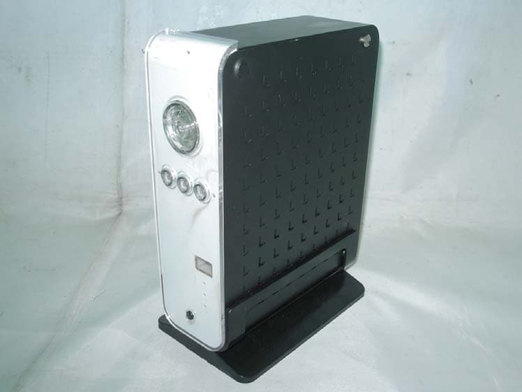
PM8MG35HDD0127
Mar 07, 2005MPEG4 Player
Equipment Class
JBP - Part 15 Class B Computing Device Peripheral
PM8AC-100
Jul 08, 2004CAR MP3 Player
Equipment Class
DXX - Part 15 Low Power Communication Device Transmitter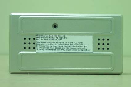
PM8CARMP3AC100
Mar 02, 2004MP3 Player WIth FM Transmitter
Equipment Class
DXX - Part 15 Low Power Communication Device Transmitter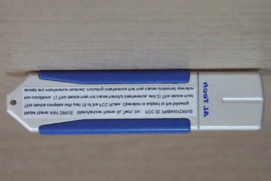
PM8ANYDRIVE
Apr 26, 2002USB Memory Device
Equipment Class
JBP - Part 15 Class B Computing Device Peripheral