PMQATR9100Advantag 9100
Asyst Technologies, Inc.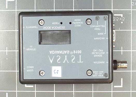
Click to zoom
Application Details
- Equipment Class
- DCD - Part 15 Low Power Transmitter Below 1705 kHz
- Date of Grant
- Oct 06, 2003
- Application Purpose
- Original Equipment
- Date of Application
- Oct 06, 2003
- Equipment Note
- Advantag 9100
- Frequency Range
- 0.13420000 - 0.13420000
- Company
- Asyst Technologies, Inc.
- Country
- United States
Documents & Files
Document Text
Text extracted from the exhibit documents filed with the FCC. Open a document above to read the original.
Users Manual
Rev. A Date: 06/05/2003 Printed on Standard Paper P/N: 2000-3160-02 Copyright ©2003 Asyst Technologies, Incorporated All rights reserved. AdvanTag 9100 AdvanTag Gateway Technical Manual Rev. AReleasedPage i AdvanTag 9100/Gateway Technical Manual Disclaimers a Disclaimers This manual may not be reproduced, either wholly or in part, for any reason whatsoever, without prior written permission from Asyst Technologies, Inc. (“Asyst”). Material contained in this manual is provided for informational purposes and is subject to change without notice. If this manual is marked “Preliminary” or “Draft,” then Asyst has not yet released a final version of the manual and the manual is likely to be incomplete and will be revised. Contact Asyst at the address below to obtain a final copy of the manual. Manual Information PCN: E12464 Part Number: 2000-3160-02 Date: 06/05/2003 Release: x Printing Description: Printed on Standard Paper. Asyst Technologies, Inc. 48761 Kato Road Fremont, California 94538 Telephone: (510) 661-5000 FAX: (510) 661-5166 Technical Support: 1-800-342-SMIF Trademarks Asyst, the Asyst logo(s), FLOUROTRAC, KPOD, ADU and MANUAFACTURING CONNECTIVITY are registered trademarks ® of Asyst Technologies, Inc. VERSAPORT, PLUS, INX, ADVAN-TAG, LINK MANAGER, SMART-TAG, SMART-STATION, SMART-STORAGE, SMART-TRAVELER, SMART-COMM, AXYS, FASTRACK, FASTMOVE, FASTLOAD, FASTORE are trademarks TM of Asyst Technologies, Inc. All other product and company names mentioned herein may be trademarks and/or service marks of their respective owners. Equipment Modification Any change, alteration, or modification to this equipment, as well as use of this equipment in a manner inconsistent with its intended use will void this equipment’s warranty and may render this equipment unsafe for use or unfit for its intended purposes. Training and Languages User training for equipment operation and maintenance is conducted in English. Translators are available on an as needed basis. English versions of the manuals and other technical materials are provided and reviewed during the training. Please contact the Asyst Training department or http://www.asyst.com for the training schedule and signup requirements. Warranty For warranty information, see Asyst’s Standard Terms and Conditions. Page iiReleasedRev. A AdvanTag 9100/Gateway Technical Manual Reader Comments a Reader Comments We welcome your comments regarding this manual. Your comments and suggestions help us to improve our publications. Please send comments and suggestions to: Asyst Technologies, Inc. Technical Publications Manager 48761 Kato Rd. Fremont CA 94538 Or fax: Attention—Tech Pubs Manager at 1-510-661-5185 Or email: [email protected] Include the following: Name: Company: Contact Phone # (in case we have questions): Email: Document Information (Name of document, Part Number, Revision): Location of comment (page number or other reference): Comments: (The more specific the comments, the more useful they are to us.) Thank you for helping to improve the manuals and to maintain accuracy. Rev. AReleasedPage iii a Acronym List AMHSAutomated Material Handling System ASCIIAmerican Standard Coding for Information Interchange ATRAdvanTag Reader CANControl Area Network CIMComputer-Integrated Manufacturing EMFElectromagnetic Field EMIElectromagnetic Interference EMOEmergency (Machine) Off ESDElectrostatic Discharge MIDMaterial IDentification OEMOriginal Equipment Manufacturer PN or P/NPart Number RFIDRadio Frequency IDentification SECSSemiconductor Equipment Communication Standard SEMISemiconductor Equipment and Materials International SMIFStandard Mechanical Interface Page ivReleasedRev. A AdvanTag 9100/Gateway Technical Manual a Rev. AReleasedPage v a Revision History DateAuthorVersionRevision Information 06/05/2003Royden TonomuraAOriginal version - release ECN E12464 Page viReleasedRev. A AdvanTag 9100/Gateway Technical Manual a Rev. AReleasedPage vii AdvanTag 9100/Gateway Technical Manual Table of Contents a Table of Contents Disclaimers . . . . . . . . . . . . . . . . . . . . . . . . . . . . . . . . . . . . . . . . . . . . . . . . . . . . . . .i Manual Information . . . . . . . . . . . . . . . . . . . . . . . . . . . . . . . . . . . . . . . . . . . . . . . . .i Trademarks . . . . . . . . . . . . . . . . . . . . . . . . . . . . . . . . . . . . . . . . . . . . . . . . . . . . . . .i Equipment Modification. . . . . . . . . . . . . . . . . . . . . . . . . . . . . . . . . . . . . . . . . . . . . .i Training and Languages . . . . . . . . . . . . . . . . . . . . . . . . . . . . . . . . . . . . . . . . . . . . .i Warranty . . . . . . . . . . . . . . . . . . . . . . . . . . . . . . . . . . . . . . . . . . . . . . . . . . . . . . . . .i Reader Comments . . . . . . . . . . . . . . . . . . . . . . . . . . . . . . . . . . . . . . . . . . . . . . . . ii Acronym List. . . . . . . . . . . . . . . . . . . . . . . . . . . . . . . . . . . . . . . . . . . . . . iii Revision History . . . . . . . . . . . . . . . . . . . . . . . . . . . . . . . . . . . . . . . . . . . .v Preface . . . . . . . . . . . . . . . . . . . . . . . . . . . . . . . . . . . . . . . . . . . . . . . . . . 1 Purpose and Audience . . . . . . . . . . . . . . . . . . . . . . . . . . . . . . . . . . . . . . . . . . . . . 1 About this Manual . . . . . . . . . . . . . . . . . . . . . . . . . . . . . . . . . . . . . . . . . . . . . . . . . 1 References . . . . . . . . . . . . . . . . . . . . . . . . . . . . . . . . . . . . . . . . . . . . . . . . . . . . . . 1 Conventions . . . . . . . . . . . . . . . . . . . . . . . . . . . . . . . . . . . . . . . . . . . . . . . . . . . . . 1 Safety Tags . . . . . . . . . . . . . . . . . . . . . . . . . . . . . . . . . . . . . . . . . . . . . . . . . . . . . . 2 Chapter 1: General Information. . . . . . . . . . . . . . . . . . . . . . . . . . . . . . . 5 Technical Data (Specifications and Outline Drawing) . . . . . . . . . . . . . . . . . . . . . . 5 Safety . . . . . . . . . . . . . . . . . …
Text truncated - open the document above for the full version.
External Photos
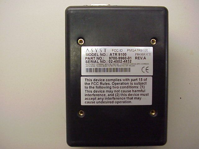
Front Back Top Bottom Side
Internal Photos
Top Cover Removed PCB #1 Removed PCB 1 Top PCB Top Closeup 1 PCB Top Closeup 2 PCB 1 Bottom PCB 1 Bottom Closeup 1 PCB 1 Bottom Closeup 2 PCB 2 Top PCB 2 Bottom
Operational Description
1 A Document No.: ATR 9100 Production Description Revision: 1.1 Page of Pages: Page 1 of 6 Issuing Dept.: STS Author: Daniel Liu/Bruce Moullette ATR 9100 Production Description REVISION DESCRIPTION OF CHANGE RELEASED BY DATE 1.0 First Draft Daniel Liu 3/11/03 2 1 DESCRIPTION OF CIRCUIT FUNCTIONS ...................ERROR! BOOKMARK NOT DEFINED. 2 ATR 9100, RADIO/PWR INTERFACE............................................................................................. 3 2.1 POWER............................................................................................................................................ 3 2.1.1 VCC3 ...................................................................................................................................... 3 2.1.2 VCC10 .................................................................................................................................... 3 2.1.3 VCC5 ...................................................................................................................................... 3 2.2 RADIO INTERFACE........................................................................................................................... 3 3 ATR 9100 DIGITAL INTERFACE .................................................................................................... 4 3.1 MICROCONTROLLER INTERFACE INITIALIZATION............................................................................ 4 3.1.1 Serial Interface ....................................................................................................................... 4 3.1.2 SRAM ...................................................................................................................................... 4 3.1.3 Flash Memory......................................................................................................................... 4 3.1.4 SW2......................................................................................................................................... 4 3.1.5 LEDs ....................................................................................................................................... 4 3.1.6 Remote Sensor ........................................................................................................................ 4 3.2 CAN................................................................................................................................................ 4 3.3 ETHERNET....................................................................................................................................... 5 4 MECHANICAL .................................................................................................................................... 5 4.1 SWITCHES........................................................................................................................................ 5 4.2 CONNECTORS.................................................................................................................................. 5 3 1 Description of Circuit Functions Introduction: The purpose of this document is to provide a product description for the Advantag 9100 electronics. The Advantag 9100 consist of two 2.8” x 3.5” size printed circuit boards, the ATR 9100,RADIO/POWER Interface (3200-1253-01), and ATR 9100, CONTROLLER (3200-1252-01). The ATR 9100, RADIO/PWR Interface contains power supplies, Controller Area Networking (CAN) driver and RFID with standard range and long range. The ATR 9100, CONTROLLER contains the Dallas Network Microcontroller (DS80C400, Intel LXT972A Dual-Speed Fast Ethernet 10/100BASE using RJ-45 connector and one RS-232 serial port. The ATR 9100,Radio/PWR Interface and ATR 9100 Controller boards are connected through a Samtec 30 pin SMT 0.050” Board Stacker. The ATR 9100 receives commands via either the Ethernet or RS 232 interface and translates these commands for use by the TI microreader. The TI micro-reader then decodes these commands to an RF protocol which address the associated transponder. The antenna is a .25inch diameter inductive loop type, which is resonated at 134.2kHz to generate the flux linkage to the transponder. The external power to the ATR9100 is a two-wire DC interface. The internal DC supplies and ground are isolated from the external supply lines to accommodate good conducted emissions performance and acceptable ESD performance. The following paragraphs outline the circuit functions: 1.1.1 VCC3 VCC3 is 3.3 volts. To assure the reliable performance of the digital circuitry, VCC3 must be at 3.3V ± 5% (between 3.17V and 3.47V). VCC3 must be verified with the input supply voltage range of 24.0VDC. VCC3 is measured with respect to signal ground. VCC3 and signal ground can be found on connector pins TP1 and J1.5 of the 3200-1253-01 PCB respectively. 1.1.2 VCC10 VCC10 is 10.0 VDC. To assure the reliable performance of the RF circuitry, VCC10 must be 10.0 VDC ± 5% (between 9.50V and 10.50V). VCC10 must be verified with the input supply voltage range of 24.0 VDC. VCC10 is measured with respect to signal ground. VCC10 and signal ground can be found on connector pins TP2 and J1.5 of the 3200-1253-01 PCB respectively. 1.1.3 VCC5 VCC5 is 5.00 volts to provide the TIRIS module must be 5.0 V ± 5% between 5.25V and 5.25V which input from VCC10. VCC5 is measured with respect to signal ground. VCC5 and signal ground can be found on pins U9.2 and J1.5 on 3000-1253-01ATR 9100, Radio/PWR INTF board respectively. 1.2 RADIO INTERFACE An off the shelve TI micro-radio is used to interface the digital command form the CPU to the target transponder. The transmit carrier is 134.2 kHz which is AM modulated to address the transponder. The transponder, when queered, responds with two tone FSK for detection by the TI receiver. . 4 2 ATR 9100 Digital Interface 2.1 Microcontroller Interface Initialization 2.1.1 Serial Interface The ATR9100 provides an RS232 interfac…
Text truncated - open the document above for the full version.
Test Report
Page 1 of 39 Report No.: FC03-022 ASYST TECHNOLOGIES TEST REPORT FOR THE ADVANTAG 9100 FCC PART 15 SUBPART C SECTIONS 15.207 & 15.209 COMPLIANCE DATE OF ISSUE: APRIL 7, 2003 PREPARED FOR: Asyst Technologies 48761 Kato Road Fremont, CA 94538 PREPARED BY: Mary Ellen Clayton CKC Laboratories, Inc. 5473A Clouds Rest Mariposa, CA 95338 P.O. No.: 332081 W.O. No.: 80115 Date of test: April 2-4, 2003 Report No.: FC03-022 This report contains a total of 31 pages and may be reproduced in full only. Partial reproduction may only be done with the written consent of CKC Laboratories, Inc. The results in this report apply only to the items tested, as identified herein. Page 2 of 39 Report No.: FC03-022 TABLE OF CONTENTS Administrative Information .............................................................................................3 Summary of Results .........................................................................................................4 Conditions for Compliance ..............................................................................................4 Approvals .........................................................................................................................4 15.31 Voltage Variation...................................................................................................5 15.31 Number Of Channels .............................................................................................5 15.33 Frequency Ranges Tested ......................................................................................5 15.35 Analyzer Bandwidth Settings ................................................................................5 15.203 Antenna Requirements.........................................................................................5 15.205 Restricted Bands ..................................................................................................5 Eut Operating Frequency .................................................................................................6 Temperature And Humidity During Testing....................................................................6 Equipment Under Test (EUT) Description ......................................................................6 Equipment Under Test .....................................................................................................6 Peripheral Devices ...........................................................................................................6 Report of Measurements ..................................................................................................7 Table 1: 15.207 Six Highest Conducted Emission Levels...................................7 Table 2: 15.209 Fundamental Emission Levels ..................................................8 Table 3: 15.209 Six Highest Radiated Emission Levels......................................9 Measurement Uncertainty ................................................................................................10 EUT Setup........................................................................................................................10 Correction Factors............................................................................................................10 Table A: Sample Calculations .............................................................................10 Test Instrumentation and Analyzer Settings ....................................................................11 Spectrum Analyzer Detector Functions ...............................................................11 Peak..........................................................................................................11 Quasi-Peak ...............................................................................................11 Average ....................................................................................................11 Testing..............................................................................................................................12 Mains Conducted Emissions................................................................................12 Radiated Emissions ..............................................................................................12 Appendix A: Test Setup Photographs..............................................................................13 Photograph Showing Mains Conducted Emissions .............................................14 Photograph Showing Mains Conducted Emissions .............................................15 Photograph Showing Radiated Emissions ...........................................................16 Photograph Showing Radiated Emissions ...........................................................17 Appendix B: Test Equipment List ...................................................................................18 Appendix C: Measurement Data Sheets ..........................................................................19 Page 3 of 39 Report No.: FC03-022 ADMINISTRATIVE INFORMATION DATE OF TEST: April 2-4, 2003 DATE OF RECEIPT: April 3, 2003 PURPOSE OF TEST: To demonstrate the compliance of the ADVANTAG 9100 with the requirements for FCC Part 15 Subpart C Sections 15.207 & 15.209 devices. TEST METHOD: ANSI C63.4 (1992) MANUFACTURER: Asyst Technologies 48761 Kato Road Fremont, CA 94538 REPRESENTATIVE: Saeed Taghipour TEST LOCATION: CKC Laboratories, Inc. 5473A Clouds Rest Mariposa, CA 95338 Page 4 of 39 Report No.: FC03-022 SUMMARY OF RESULTS As received, the Asyst Technologies ADVANTAG 9100 was found to be fully compliant with the following standards and specifications: United States ! FCC Part 15 Subpart C Sections 15.207 & 15.209 ! ANSI C63.4 (1992) method CONDITIONS FOR COMPLIANCE No modifications to the EUT were necessary to comply. APPROVALS QUALITY ASSURANCE:TEST PERSONNEL: Steve Behm, Director of Engineering Services and Qualit…
Text truncated - open the document above for the full version.
Test Setup Photos
PHOTOGRAPH SHOWING MAINS CONDUCTED EMISSIONS Mains Conducted Emissions - Front View PHOTOGRAPH SHOWING MAINS CONDUCTED EMISSIONS Mains Conducted Emissions - Side View PHOTOGRAPH SHOWING RADIATED EMISSIONS Radiated Emissions - Front View PHOTOGRAPH SHOWING RADIATED EMISSIONS Radiated Emissions - Back View
Contact Information
Applicant
Yolanda Ma(Product Manager)
Technical Contact
CKC Laboratories, Inc.Mary Ellen Clayton
[email protected]209-966-4257
5473-A Clouds Rest · Mariposa, California · United States
Non-Technical Contact
CKC Laboratories, Inc.Mary Ellen Clayton
[email protected]209-966-5240
Test Firm
CKC Laboratories, Inc.Steve Behm
Technical Specifications
| # | Rule Parts | Frequency Range | Power Output |
|---|---|---|---|
| 1 | 15C | 0.1342 MHz - 0.1342 MHz | - |
Other Applications from Asyst Technologies, Inc.
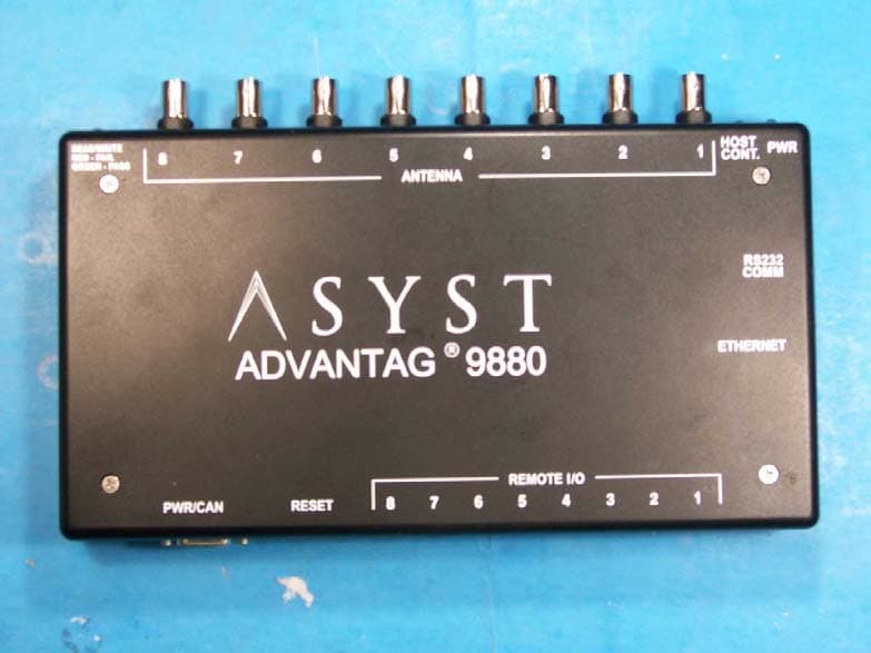
PMQATR9880
Dec 09, 2007RFID Tag Reader/Multiplexer
Equipment Class
DXT - Part 15 Low Power Transceiver, Rx Verified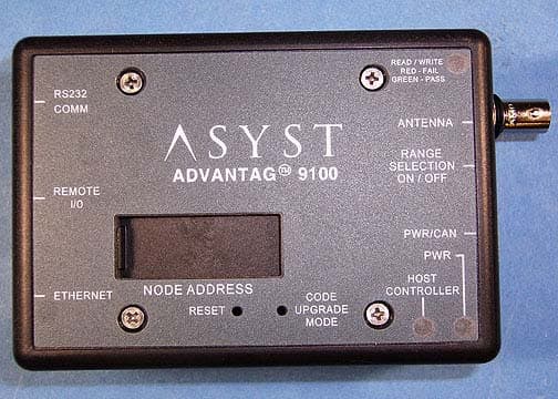
PMQATR9100ROHS
Nov 12, 2006Single Antenna Reader
Equipment Class
DXT - Part 15 Low Power Transceiver, Rx Verified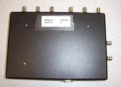
PMQATR9800
Jun 11, 20068 Antenna Industrial Radio
Equipment Class
DXT - Part 15 Low Power Transceiver, Rx Verified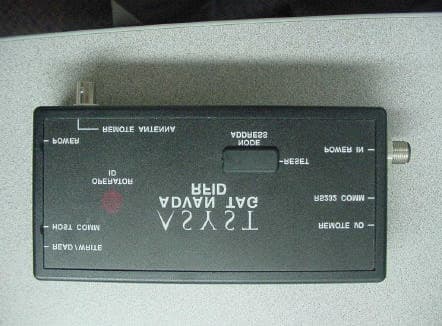
PMQATR9000
Jun 24, 2001ID Tag Reader/Writer Module
Equipment Class
DXT - Part 15 Low Power Transceiver, Rx Verified