PMQATR9880RFID Tag Reader/Multiplexer
Asyst Technologies, Inc.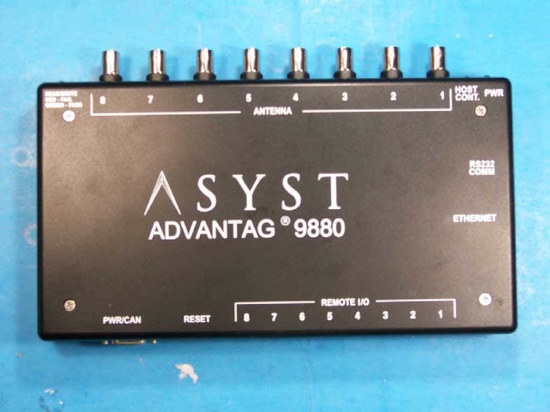
Click to zoom
Application Details
- Equipment Class
- DXT - Part 15 Low Power Transceiver, Rx Verified
- Date of Grant
- Dec 09, 2007
- Application Purpose
- Original Equipment
- Date of Application
- Dec 06, 2007
- Equipment Note
- RFID Tag Reader/Multiplexer
- Frequency Range
- 0.13400000 - 0.13400000
- Company
- Asyst Technologies, Inc.
- Country
- United States
Documents & Files
Document Text
Text extracted from the exhibit documents filed with the FCC. Open a document above to read the original.
Cover Letter(s)
Non-Conformities FCC ID: PMQATR9880 (CKC CS Ref # E07-000117-FCC-01) The items listed below represent requests for infor mation following review of this application for cer tification under United States (FCC) regulations. Further question may arise pending review of responses to t hese items. OK # Non-Conformity or Comment Submitted Response Respondent / Date of Response X 1 The confidentiality request includes a request to hold product manuals confidential. Please clarify exactly which documen tation is included in this request. This item refers to the user’s manual. CKC Labs 12/ 3/07 X 2 ID Label is somewhat burry. Please consider su bmitting an updated label exhibit which is clear (eg, a sample drawing or sep arate photo of the label). Revised labels have been uploaded. CKC Labs 12/3/07 X 3 In the operational description provided (on pag e 12), in the paragraph pertaining to the operation of the equipment, the f ollowing is listed ,” The Operating program is field upgradeable using PickIt 2.” Please clarify; are the operating characteristics of the radio field upgrad eable? The radio is not upgradable. CKC Labs 12/3/07 X 4 The grantee information provided on form 731 is inconsistent with that listed on the FCC website. Please submit any changes in g rantee information to the FCC pursuant to 47 CFR §2.926 It is listed on the web site but the physical address does not match the one provided. Note: bot h Addresses are in Fremont, California. Customer will contact the FCC to update the address. CKC Labs 12/3/07 X 5 The test report on page 4 indicates compliance with 15.203 via unique antenna connector – this is not the case, the equip ment does not have a unique connector and is therefore subject to professional installation as indicated in the manual. Please clarify if there is other infor mation contrary to this? A revised test report has been uploaded. CKC Labs 12/3/07 X 6 Regarding 15.203: The use of professionally ins talled antennas requires proper justification. Please provide a document co ntaining the following information: 1) method of marketing, 2) entity(ies) to perform installation, 3) application - target market, and 4) why does this e quipment require professional installation (what makes this equipmen t unique, sophisticated, complex or specialized? 1. Presentation and sales pitch by Asyst’s professional sales team and marketing team 2. The mounting features are specific to the Asyst antenna and will not work properly with other antenna. 3. Semiconductor Companies (i.e. Intel, Toshiba, TI) 4. The unit is to be professionally installed by Asyst trained engineers and technicians CKC Labs 12/3/07 X 7 Regarding 15.205: Please declare the RF tag ret urn frequency. FSK modulated tone frequencies 123.2 kHz and 134.2 k, 11.0 kHz FSK CKC Labs 12/3/07
External Photos
External Photos Top Bottom Front Back Left Side Right Side
ID Label/Location Info
Draft Rev. Ax12000-6224-02Page 9 AdvanTag 9880 Technical Manual Chapter 1: General Information Labeling Labeling TABLE 2Labels No.LabelDescription/Location 1 AdvanTag 9880 Reader labelThe AdvanTag 9880 Reader Label identifies the various components of the unit. It is located on the top of the reader. See Figure 2 on page 10. 2 Serial Number Label (9880 Reader)The model and serial number label for the AdvanTag 9880 Reader is located on the bottom of the unit. See Figure 2 on page 10. These numbers are required when contacting Asyst Technologies for any matter concerning the equipment. 3 FCC LabelThe FCC label for the AdvanTag 9880 Reader is located on the bottom of the unit. See Figure 2 on page 10. 4 RoHSThe presence of this label indicates compliance with regulations regarding Restriction of Hazardous Substances (RoHS). Page 102000-6224-02Draft Rev. Ax1 AdvanTag 9880 Technical Manual Chapter 1: General Information Labeling Location of Labels used on the AdvanTag FIGURE 2 Label Locations, AdvanTag 9880 Reader Serial Number Label RoHS Label AdvanTag 9880 Reader Label FCC Label
ID Label/Location Info
ID Label Location ART9880 label 002 ART9880 label 004
Internal Photos
Internal Photos Top Top, cover removed PCB Top PCB Top, left half PCB Top, right half PCB Bottom PCB Bottom, left half PCB Bottom, right half
Test Report
Page 1 of 49 Report No.: FC07-086A ADDENDUM TO ASYST TECHNOLOGIES TEST REPORT FC07-086 FOR THE RFID TAG READER/MULTIPLEXER, ATR 9880 FCC PART 15 SUBART B SECTIONS 15.107 & 15.109 CLASS B AND FCC PART 15 SUBPART C SECTION 15.207 & 15.209 TESTING DATE OF ISSUE: NOVEMBER 30, 2007 PREPARED FOR: Asyst Technologies 46897 Bayside Parkway Fremont, CA 94538-6572 PREPARED BY: Mary Ellen Clayton CKC Laboratories, Inc. 5046 Sierra Pines Drive Mariposa, CA 95338 W.O. No.: 87011Date of test: August 31 - October 11, 2007 Report No.: FC07-086A This report contains a total of 49 pages and may be reproduced in full only. Partial reproduction may only be done with the written consent of CKC Laboratories, Inc. The results in this report apply only to the items tested, as identified herein. Page 2 of 49 Report No.: FC07-086A TABLE OF CONTENTS Administrative Information .............................................................................................3 Approvals .........................................................................................................................3 Conditions During Testing...............................................................................................3 FCC 15.31(e) Voltage Variation......................................................................................4 FCC 15.31(m) Number Of Channels ...............................................................................4 FCC 15.33(a) Frequency Ranges Tested .........................................................................4 FCC 15.35 Analyzer Bandwidth Settings ........................................................................4 FCC 15.203 Antenna Requirements ................................................................................4 EUT Operating Frequency ...............................................................................................4 Temperature And Humidity During Testing....................................................................4 Equipment Under Test (EUT) Description ......................................................................5 Equipment Under Test .....................................................................................................5 Peripheral Devices ...........................................................................................................5 Report of Emissions Measurements.................................................................................6 Testing Parameters...............................................................................................6 FCC 15.107 Conducted Emissions ......................................................................8 FCC 15.109 Radiated Emissions .........................................................................17 FCC 15.207 Conducted Emissions ......................................................................23 FCC 15.209 Radiated Emissions .........................................................................32 Occupied Bandwidth............................................................................................48 Page 3 of 49 Report No.: FC07-086A ADMINISTRATIVE INFORMATION DATE OF TEST: August 31 - October 11, 2007 DATE OF RECEIPT: August 31, 2007 REPRESENTATIVE: Tou Vang MANUFACTURER: Asyst Technologies 46897 Bayside Parkway Fremont, CA 94538-6572 TEST LOCATION: CKC Laboratories, Inc. 1120 Fulton Place Fremont, CA 94539 TEST METHOD: ANSI C63.4 (2003) PURPOSE OF TEST: Original Report: To perform the testing of the RFID Tag Reader/Multiplexer, ATR 9880 with the requirements for FCC Part 15 Subpart B Sections 15.107 & 15.109 Class B and FCC Part 15 Subpart C Section 15.207 & 15.209 devices. Addendum A: To revise the 15.203 statement on page 4 with no new testing. APPROVALS Steve Behm, Director of Engineering Services QUALITY ASSURANCE:TEST PERSONNEL: Joyce Walker, Quality Assurance Administrative Manager Art Rice, EMC Engineer Amrinder Brar, EMC Engineer/Lab Manager Norberto Gamez Jr., Test Technologist Christine Nicklas, Senior EMC Engineer/Consultant CONDITIONS DURING TESTING During radiated emissions caps were added to enet. Page 4 of 49 Report No.: FC07-086A FCC 15.31(e) Voltage Variations Transmit fundamental was also measured at -/+15% (20.4 and 27.6 Volts) and no change in the level was seen. Test Equipment FunctionModel/TypeManufacturerSerial No.Cal DateCal Due Spectrum AnalyzerE4446AAgilentUS4430040803-05-0703-05-09 Active loop6502EMCO207806-11-0706-11-09 CableRG214/UPasternackANP0530004-05-0704-05-09 CableRG214/UPasternackANP0529604-05-0704-05-09 Digital Multimeter23Fluke5454158007-18-0607-18-08 DC supply72-6610Tenma020171409-07-0609-07-08 CableRG214/UPasternackANP0529904-05-0704-05-09 FCC 15.31(m) Number Of Channels This device operates on a single channel. FCC 15.33(a) Frequency Ranges Tested 15.107 Conducted Emissions: 150 kHz – 30 MHz 15.109 Radiated Emissions: 9 kHz – 1000 MHz 15.207 Conducted Emissions: 150 kHz – 30 MHz 15.209 Radiated Emissions: 9 kHz – 1000 MHz FCC SECTION 15.35: ANALYZER BANDWIDTH SETTINGS PER FREQUENCY RANGE TESTBEGINNING FREQUENCYENDING FREQUENCYBANDWIDTH SETTING RADIATED EMISSIONS9 kHz150 kHz200 Hz RADIATED EMISSIONS150 kHz30 MHz9 kHz RADIATED EMISSIONS30 MHz1000 MHz1 MHz FCC 15.203 Antenna Requirements The antenna requires professional installation; therefore the EUT complies with Section 15.203 of the FCC rules. EUT Operating Frequency The EUT was operating at 134.205 kHz. Temperature And Humidity During Testing The temperature during testing was within +15°C and + 35°C. The relative humidity was between 20% and 75%. Page 5 of 49 Report No.: FC07-086A EQUIPMENT UNDER TEST (EUT) DESCRIPTION The customer declares the EUT tested by CKC Laboratories was representative of a production unit. EQUIPMENT UNDER TEST RFID Tag Reader/Multiplexer Manuf: Asyst Technologies Model: ATR 9880 Serial: 001 FCC ID: pending Antenna Manuf: Asyst Technologies Model: PN 9701-2883-04 Rev 002 Serial: 4 PERIPHE…
Text truncated - open the document above for the full version.
Test Setup Photos
Test Setup Photos
Contact Information
Applicant
Yolanda Ma(Product Manager)
Technical Contact
CKC Laboratories, Inc.Mary Ellen Clayton
[email protected]209-966-5240
5046 Sierra Pines Dr. · Mariposa, California · United States
Non-Technical Contact
CKC Laboratories, Inc.Mary Ellen Clayton
[email protected]209-966-5240
Test Firm
CKC Laboratories, Inc.Steve Behm
Technical Specifications
| # | Rule Parts | Frequency Range | Power Output |
|---|---|---|---|
| 1 | 15C | 0.134 MHz - 0.134 MHz | - |
Other Applications from Asyst Technologies, Inc.
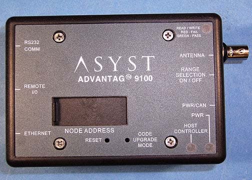
PMQATR9100ROHS
Nov 12, 2006Single Antenna Reader
Equipment Class
DXT - Part 15 Low Power Transceiver, Rx Verified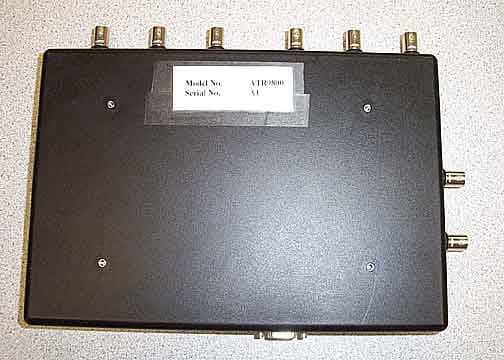
PMQATR9800
Jun 11, 20068 Antenna Industrial Radio
Equipment Class
DXT - Part 15 Low Power Transceiver, Rx Verified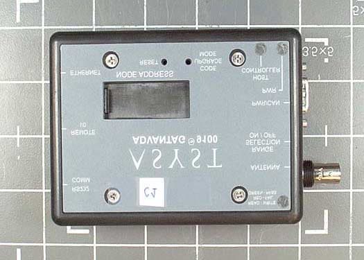
PMQATR9100
Oct 06, 2003Advantag 9100
Equipment Class
DCD - Part 15 Low Power Transmitter Below 1705 kHz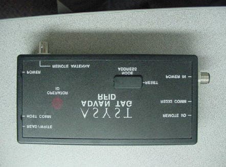
PMQATR9000
Jun 24, 2001ID Tag Reader/Writer Module
Equipment Class
DXT - Part 15 Low Power Transceiver, Rx Verified