PMQATR9100ROHSSingle Antenna Reader
Asyst Technologies, Inc.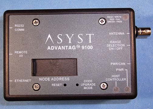
Click to zoom
Application Details
- Equipment Class
- DXT - Part 15 Low Power Transceiver, Rx Verified
- Date of Grant
- Nov 12, 2006
- Application Purpose
- Original Equipment
- Date of Application
- Nov 12, 2006
- Equipment Note
- Single Antenna Reader
- Frequency Range
- 0.13400000 - 0.13400000
- Company
- Asyst Technologies, Inc.
- Country
- United States
Documents & Files
Document Text
Text extracted from the exhibit documents filed with the FCC. Open a document above to read the original.
Cover Letter(s)
Non-Conformities FCC ID: PMQATR9100ROHS (Ref # E06-000231-1) The items listed below represent requests for information following review of this application. Further question may arise pending review of responses to these items. 1 Please provide justification for professional installation of this equipment. Specifically, please provide a statement of the method of marketing, and a declaration of the intended use of the equipment. Response: This is not a consumer product. It is used exclusively in semiconductor factories. It is professionally installed by engineers and technicians who are trained by Asyst. Also, we do not warrant our product when used with non-Asyst antennas. 2 The users manual indicates in one part that the two part warning is not located on the device yet in another part, it shows the location of the two part warning statement on the equipment. Since the device is larger than the palm of a person's hand, the FCC requires the equipment to have the statement on the label. Since the provided labels do not show compliance with this requirement, please provide updated label exhibit showing compliance. Please also amend users manual for consistency. Response: A revised users manual and a revised label have been uploaded. 3 Please provide the return frequency of the RFID tag. Response: Frequency Shift Key 134.2 kHz or 123.3 kHz.
External Photos
Front Back Top Bottom Left Side Right Side
Internal Photos
Antenna Inside of Top Cover Inside of Bottom Cover Top Board Top Side Top Board Bottom Side Top of the Bottom Board Bottom of the Bottom Board
Operational Description
A Revision: 1.0 Page of Pages: Page 1 of 2 Issuing Dept.: STS Author: Gary Dow 1.0 OVERVIEW Asyst’s ATR9100-RoHS electronics consists of a two printed circuit board which contains power supplies, Controller Area Networking CAN driver and a RFID radio with standard range and long range. The digital PCB contains a Dallas Network Microcontroller with 16 x 4 MHz CPU, Fast Ethernet 10BASE using RJ-45 connector and one RS-232 port. There is also a RFID radio/power supply PCB which contains +5, +10, +3.3 V power supplies for various reader functions and a 134.2 KHz RFID transceiver with interface circuitry to the host processor. 1.1 ATR9100-RoHS has the following primary functions 1.1.1 A serial port to a serial host and CAN Bus and 10BASE-T/100Base-TX Ethernet and RFID with one Antenna Port and one Remote Presence Port 1.1.1.1 Serial port to a single serial host connection 1.1.1.2 Provide power on the serial and CAN Bus ports for power connected devices 1.1.1.3 Ethernet 10BASE-T/100Base-TX and RFID 2.0 MECHANICAL SPECIFICATIONS Size: 1.5” x 3.25” x 4.5” 3.0 ELECTRICAL SPECIFICATIONS +24 VDC @2A max 4.0 ATR9100-RoHS Antenna Ports 4.1 Introductions The ATR91000-RoHS digital PCB provides the external power interface to the outside world in addition to a CAN external interface and a digital interface from the microprocessor circuitry to the RFID radio circuitry on the RFID radio/power supply PCB. 4.2 ATR9100-RoHS contains the following sub-circuits which will be addressed individually 4.2.1 RFID radio/power supply PCB 4.2.2 DC/DC converters: • +24Vdc @2A (input) • +3.3Vdc @500mA (output) for on board logic chips • +10Vdc @500mA for extended range RFID circuitry • +5Vdc @200mA for the RFID reader module 4.2.3 Internal Power Generation • +12Vdc switch module converter – switch mode converter U15 provides 12Vdc ±2%, monitored at TP7, to the RF power circuits and remote IO presence port of the ATR9100-RoHS • +5Vdc linear regulator • +3.3Vdc switch mode converter • +1.8Vdc for the micro controller core 4.2.4 Digital PCB 4.2.4.1 Micro Controller Micro controller with the 16 MHz oscillator communicate with the RFID READER through the serial communication link. Effectively, the antenna circuit is a series mode, resonate, LC circuit which is resonated very close to the 134.2 KHz carrier to achieve maximum voltage at the antenna node, approximately 200V peak-peak. This voltage divided by the impedance of the antenna at the 134.2 KHz determines the magnetic field generated by the antenna. The later the magnetic field the longer the read/write range of the transponder. 4.2.4.2 CAN Interface Level translator CAN buffer chip translates the CAN Bus signal levels, at the J1 connector, to 3.3Vdc signals compatible with the microprocessor 4.2.4.3 Ethernet The Micro Controller is built in 10/100 Media Access Controller (MAC), the Intel LXT972A 3.3V Dual-Speed Fast Ethernet/IEEE 802.3- compliant PHY Transceiver that directly supports 10BASE-T application. It provides a Media Independent Interface (MII) for easy attachment to 10/100 Media Access Controllers (MACs). 4.2.4.4 CAN 2.0B Controller The DS80C400 incorporates one CAN Controller that is fully compliant with the CAN 2.0B specification. The CAN controller support the use of 11-bit standard or 19-bit extended acceptance identifiers for up to 15 messages, with the standard 8-Byte data field, in each message and global masks. The Micro Controller provides two CAN interface signals C0TX CAN0 Transmit Output and C0RX CAN0 Receive Input. These two CAN interface C0TX and C0RX are connected to the J1 pin 2 and pin 7, respectively. 4.2.4.5 Serial Ports The ATR9100-RoHS provides 3 serial ports that can operate simultaneously and can be configure for different braud rate or mode. The RS-232 serial ports reside on the radio board and the CAN and fast ethernet port reside on the digital board.
Test Report
Page 1 of 47 Report No.: FC06-046 ASYST TECHNOLOGIES TEST REPORT FOR THE SINGLE ANTENNA MULTIPLEXER, ATR-9100 ROHS FCC PART 15 SUBPART C SECTIONS 15.207 & 15.209, SUBPART B SECTIONS 15.107 & 15.109 CLASS A AND RSS-210 COMPLIANCE DATE OF ISSUE: AUGUST 17, 2006 PREPARED FOR: Asyst Technologies 46897 Bayside Parkway Fremont, CA 94538-6572 PREPARED BY: Mary Ellen Clayton CKC Laboratories, Inc. 5046 Sierra Pines Drive Mariposa, CA 95338 P.O. No.: 45418 W.O. No.: 85518 Date of test: August 4-10, 2006 Report No.: FC06-046 This report contains a total of 47 pages and may be reproduced in full only. Partial reproduction may only be done with the written consent of CKC Laboratories, Inc. The results in this report apply only to the items tested, as identified herein. Page 2 of 47 Report No.: FC06-046 TABLE OF CONTENTS Administrative Information .............................................................................................4 FCC to Canada Standard Correlation Matrix...................................................................5 Conditions for Compliance ..............................................................................................5 Approvals .........................................................................................................................5 FCC 15.31(m) Number Of Channels ...............................................................................6 FCC 15.33(a) Frequency Ranges Tested .........................................................................6 FCC 15.35 Analyzer Bandwidth Settings ........................................................................6 FCC 15.203 Antenna Requirements ................................................................................6 FCC 15.205 Restricted Bands..........................................................................................6 EUT Operating Frequency ...............................................................................................6 Temperature And Humidity During Testing....................................................................6 Equipment Under Test (EUT) Description ......................................................................7 Equipment Under Test .....................................................................................................7 Peripheral Devices ...........................................................................................................7 Report of Measurements ..................................................................................................8 FCC 15.31(e) Voltage Variation..........................................................................8 Table 1: FCC 15.107 Six Highest Conducted Emission Levels ..........................11 Table 2: FCC 15.109 Six Highest Radiated Emission Levels .............................12 Table 3: FCC 15.207 Six Highest Conducted Emission Levels ..........................13 Table 4: FCC 15.209 Fundamental Emission Levels ..........................................14 Table 5: FCC 15.209 Six Highest Radiated Emission Levels: 9 kHz - 30 MHz .15 Table 6: FCC 15.209 Six Highest Radiated Emission Levels: 30-1000 MHz.....16 20dB Bandwidth Plot ...........................................................................................17 EUT Setup........................................................................................................................18 Correction Factors............................................................................................................18 Table A: Sample Calculations .............................................................................18 Test Instrumentation and Analyzer Settings ....................................................................19 Spectrum Analyzer Detector Functions ...............................................................19 Peak..........................................................................................................19 Quasi-Peak ...............................................................................................19 Average ....................................................................................................19 EUT Testing.....................................................................................................................20 Mains Conducted Emissions................................................................................20 Radiated Emissions ..............................................................................................20 Appendix A: Test Setup Photographs..............................................................................21 Photograph Showing Mains Conducted Emissions .............................................22 Photograph Showing Mains Conducted Emissions .............................................23 Photograph Showing Mains Conducted Emissions .............................................24 Photograph Showing Mains Conducted Emissions .............................................25 Photograph Showing Radiated Emissions ...........................................................26 Photograph Showing Radiated Emissions ...........................................................27 Page 3 of 47 Report No.: FC06-046 Photograph Showing Radiated Emissions ...........................................................28 Photograph Showing Radiated Emissions ...........................................................29 Appendix B: Test Equipment List ...................................................................................30 Appendix C: Measurement Data Sheets ..........................................................................31 Page 4 of 47 Report No.: FC06-046 ADMINISTRATIVE INFORMATION DATE OF TEST: August 4-10, 2006 DATE OF RECEIPT: August 4, 2006 MANUFACTURER: Asyst Technologies 46897 Bayside Parkway Fremont, CA 94538-6572 REPRESENTATIVE: Tou Vang TEST LOCATION: CKC Lab…
Text truncated - open the document above for the full version.
Test Setup Photos
PHOTOGRAPH SHOWING MAINS CONDUCTED EMISSIONS Mains Conducted Emissions - Front View PHOTOGRAPH SHOWING MAINS CONDUCTED EMISSIONS Mains Conducted Emissions - Front View PHOTOGRAPH SHOWING MAINS CONDUCTED EMISSIONS Mains Conducted Emissions - Side View PHOTOGRAPH SHOWING MAINS CONDUCTED EMISSIONS Mains Conducted Emissions - Side View PHOTOGRAPH SHOWING RADIATED EMISSIONS Radiated Emissions - Front View PHOTOGRAPH SHOWING RADIATED EMISSIONS Radiated Emissions - Back View PHOTOGRAPH SHOWING RADIATED EMISSIONS Radiated Emissions - Mag Loop PHOTOGRAPH SHOWING RADIATED EMISSIONS Radiated Emissions - Mag Loop
Contact Information
Applicant
Yolanda Ma(Product Manager)
Technical Contact
CKC Laboratories, Inc.Mary Ellen Clayton
[email protected]800-500-4362
5046 Sierra Pines Drive · Mariposa, California · United States
Test Firm
CKC Laboratories, Inc.Steve Behm
Technical Specifications
| # | Rule Parts | Frequency Range | Power Output |
|---|---|---|---|
| 1 | 15C | 0.134 MHz - 0.134 MHz | - |
Other Applications from Asyst Technologies, Inc.
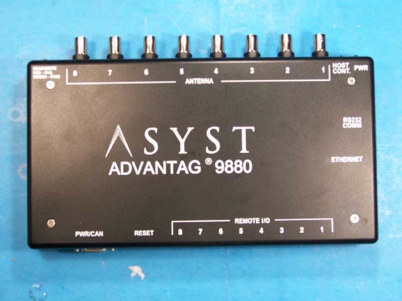
PMQATR9880
Dec 09, 2007RFID Tag Reader/Multiplexer
Equipment Class
DXT - Part 15 Low Power Transceiver, Rx Verified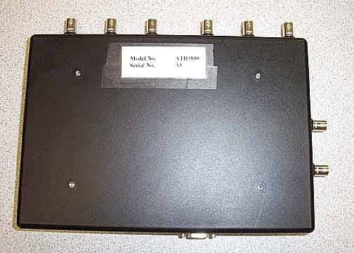
PMQATR9800
Jun 11, 20068 Antenna Industrial Radio
Equipment Class
DXT - Part 15 Low Power Transceiver, Rx Verified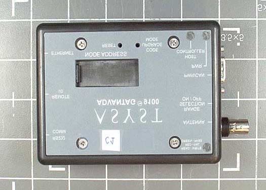
PMQATR9100
Oct 06, 2003Advantag 9100
Equipment Class
DCD - Part 15 Low Power Transmitter Below 1705 kHz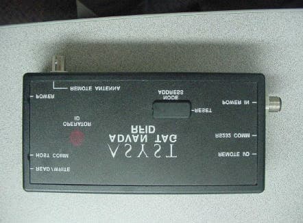
PMQATR9000
Jun 24, 2001ID Tag Reader/Writer Module
Equipment Class
DXT - Part 15 Low Power Transceiver, Rx Verified