PMQATR98008 Antenna Industrial Radio
Asyst Technologies, Inc.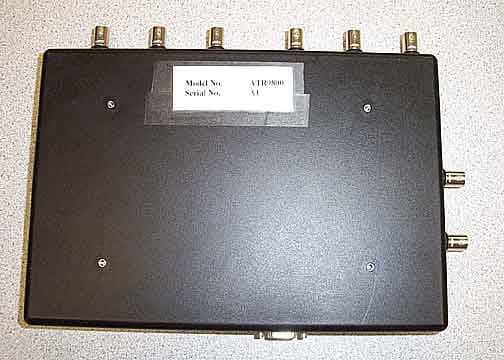
Click to zoom
Application Details
- Equipment Class
- DXT - Part 15 Low Power Transceiver, Rx Verified
- Date of Grant
- Jun 11, 2006
- Application Purpose
- Original Equipment
- Date of Application
- Jun 11, 2006
- Equipment Note
- 8 Antenna Industrial Radio
- Frequency Range
- 0.13400000 - 0.13400000
- Company
- Asyst Technologies, Inc.
- Country
- United States
Documents & Files
Document Text
Text extracted from the exhibit documents filed with the FCC. Open a document above to read the original.
Cover Letter(s)
Non-Conformities FCC ID: PMQATR9800 (Ref # E06-000 161-1) The items listed below represent requests for infor mation following review of this application. Furth er question may arise pending review of responses t o these items. OK # Non-Conformity or Comment Submitted Response Respondent / Date of Response 1 Users manual may not be held confidential withou t proper justification. Please provide further clarification as to why the users manual may be held confidential. Updated confidentiality letter provided. 6/6/06 CKC Labs 2 The correct FCC label statement in accordance wi th 15.19 is shown in the users manual , but is not provided in the label exh ibits. Please provide updated label information showing the FCC two-part warning. Updated label exhibit provided. 6/5/06 CKC Labs 3 In the interior photos, there appears to be a da ughter card. Please clarify whether or not this is the case. If so, please pro vide photos of the main PCB under the card and the back side of the daughter ca rd. Additional photos provided. 6/5/06 CKC Labs 4 It is not clear from the operational description whether the equipment operates on multiple antenna ports simultaneously. Please clarify. “The circuitry cannot operate more than one antenna at a time.” 6/5/06 CKC Labs 5 The users manual claims the device complies with 15.203 via professional installation. This method of compliance requires f urther information; please provide the following: The intended use of the pro duct, the method of marketing the equipment and clear documentation of the installation requirements. “This is not a consumer product. It is used exclusively in semiconductor factories. It is professionally installed by engineers and technicians who are trained by Asyst. Also, we do not warrant our product when used with non-Asyst antennas. Mounting features are specific to the Asyst antenna and will not properly hold another antenna.” 6/5/06 CKC Labs 6 Emissions appear to have been measured at a dist ance closer than specified by 15.209 for the frequency range below 30 MHz. Pl ease confirm that the correction factor is applied in accordance with 15. 31(f) 40dB per decade or as measured. If measured, please provide falloff data . The 40dB/decade correction factor was applied, I edited one of the reading in "FCRE07A1-15.209-9k-30m-MAGLOOP-MAX-OUTDOORS_ATR9800 new" there was a -80dB since testing was performed 2 decades away from the specified distance. 6/5/06 CKC Labs 7 Please confirm whether antenna positioning was a djusted to maximize The antennas were repositioned to 6/5/06 CKC Labs emissions from the EUT. maximize the emissions. CKC CS Note: Discussed this issue with engineer overseeing testing. Antenna maximization was properly performed.
External Photos
Top Bottom
ID Label/Location Info
Rev. Ax2DraftPage 10 AdvanTag 9800 Technical Manual Chapter 1: General Information Labeling a Location of Labels used on the AdvanTag FIGURE 2 Label Locations, AdvanTag 9800 Reader Serial Number Label FCC Label AdvanTag 9800 Reader Label
ID Label/Location Info
Rev. Ax2DraftPage 9 AdvanTag 9800 Technical Manual Chapter 1: General Information Labeling a Labeling TABLE 2Labels No.LabelDescription/Location 1 AdvanTag 9800 Reader labelThe AdvanTag 9800 Reader Label identifies the various components of the unit. It is located on the top of the reader. See Figure 2 on page 10. 2 Serial Number Label (9800 Reader)The model and serial number label for the AdvanTag 9800 Reader is located on the bottom of the unit. See Figure 2 on page 10. These numbers are required when contacting Asyst Technologies for any matter concerning the equipment. 3 FCC LabelThe FCC label for the AdvanTag 9800 Reader is located on the bottom of the unit. See Figure 2 on page 10.
Internal Photos
Response # 3 for additional internal photos: Daughter Board Top Bottom of Daughter Board
Internal Photos
Top with Chassis cover removed Top Board Left Side Top Board Center Top Board Right Side Bottom of Board Bottom of Board Left Side Bottom of Board Center Bottom of Board Right Side Antenna
Operational Description
Operational Description - 884302 Asyst's 8 Port ATR9800 electronics consist of printed circuit board which contains power supplies, Controller Area Networking CAN driver and RFID with standard range and long range. which contains the Dallas Network Microcontroller with 16MHz x 4 CPU, Fast Ethernet 10BASE using RJ-45 connector. One RS-232 serial port, additional serial port for software debug configurable by option which share the same RJ-45 remote presence connector. 8 antennas and 8 remote presence RJ45 connectors. 8 Port ATR has the following primary functions: 8 ports Antenna are switched using 8 9000 Series/Mold SIP Reed Relays from COTO Technology A serial port to a single serial host connection A protocol converter from SECS to ASCII for a variety applications Provide power on the serial and CAN Bus ports for power connected devices A Ethernet 10Base-T/100Base-TX and RFI
Test Report
Page 1 of 24 Report No.: FC05-075 ASYST TECHNOLOGIES TEST REPORT FOR THE 8 ANTENNA INDUSTRIAL RADIO, ATR9800 FCC PART 15 SUBPART C SECTION 15.209 COMPLIANCE DATE OF ISSUE: DECEMBER 15, 2005 PREPARED FOR: Asyst Technologies 48633 Warm Springs Blvd. Fremont, CA 94539 PREPARED BY: Mary Ellen Clayton CKC Laboratories, Inc. 5046 Sierra Pines Drive Mariposa, CA 95338 P.O. No.: 337116 W.O. No.: 84302 Date of test: October 17 - December 9, 2005 Report No.: FC05-075 This report contains a total of 24 pages and may be reproduced in full only. Partial reproduction may only be done with the written consent of CKC Laboratories, Inc. The results in this report apply only to the items tested, as identified herein. Page 2 of 24 Report No.: FC05-075 TABLE OF CONTENTS Administrative Information .............................................................................................3 Conditions for Compliance ..............................................................................................4 Approvals .........................................................................................................................4 FCC 15.31(e) Voltage Variation......................................................................................5 FCC 15.31(m) Number Of Channels ...............................................................................5 FCC 15.33(a) Frequency Ranges Tested .........................................................................5 FCC 15.35 Analyzer Bandwidth Settings ........................................................................5 EUT Operating Frequency ...............................................................................................5 Temperature And Humidity During Testing....................................................................5 Equipment Under Test (EUT) Description ......................................................................6 Equipment Under Test .....................................................................................................6 Peripheral Devices ...........................................................................................................6 Report of Measurements ..................................................................................................7 Table 1: FCC 15.209 Six Highest Radiated Emission Levels: 9 kHz - 30 MHz .7 Table 2: FCC 15.209 Six Highest Radiated Emission Levels: 30-1000 MHz.....8 Occupied Bandwidth............................................................................................9 EUT Setup........................................................................................................................10 Correction Factors............................................................................................................10 Table A: Sample Calculations .............................................................................10 Test Instrumentation and Analyzer Settings ....................................................................11 Spectrum Analyzer Detector Functions ...............................................................11 Peak..........................................................................................................11 Quasi-Peak ...............................................................................................11 Average ....................................................................................................11 EUT Testing.....................................................................................................................12 Radiated Emissions ..............................................................................................12 Appendix A: Test Setup Diagram and Photographs ........................................................13 Test Set Up Diagram for Outdoor 9 kHz to 30 MHz Testing..............................14 Photograph Showing Radiated Emissions ...........................................................15 Photograph Showing Radiated Emissions ...........................................................16 Appendix B: Test Equipment List ...................................................................................17 Appendix C: Measurement Data Sheets ..........................................................................18 Page 3 of 24 Report No.: FC05-075 ADMINISTRATIVE INFORMATION DATE OF TEST: October 17 - December 9, 2005 DATE OF RECEIPT: October 17, 2005 MANUFACTURER: Asyst Technologies 48633 Warm Springs Blvd. Fremont, CA 94539 REPRESENTATIVE: Bhavin Shah TEST LOCATION: CKC Laboratories, Inc. 1120 Fulton Place Fremont, CA 94539 TEST METHOD: ANSI C63.4 (2003) PURPOSE OF TEST: To demonstrate the compliance of the 8 Antenna Industrial Radio, ATR9800 with the requirements for FCC Part 15 Subpart C Section 15.209 devices. Page 4 of 24 Report No.: FC05-075 CONDITIONS FOR COMPLIANCE No modifications to the EUT were necessary to comply. Conducted emissions not required for this device. APPROVALS Steve Behm, Director of Engineering Services QUALITY ASSURANCE:TEST PERSONNEL: Joyce Walker, Quality Assurance Administrative Manager Stephen J. Goulet, EMC Technician Page 5 of 24 Report No.: FC05-075 FCC 15.31(e) Voltage Variations Voltages were varied from 85 -115% of normal and no notable variations in RF output were observed. FCC 15.31(m) Number Of Channels This device operates on a single channel. FCC 15.33(a) Frequency Ranges Tested 15.209 Radiated Emissions: 9 kHz – 1000 MHz FCC SECTION 15.35: ANALYZER BANDWIDTH SETTINGS PER FREQUENCY RANGE TESTBEGINNING FREQUENCYENDING FREQUENCYBANDWIDTH SETTING RADIATED EMISSIONS9 kHz150 kHz200 Hz RADIATED EMISSIONS150 kHz30 MHz9 kHz RADIATED EMISSIONS30 MHz1000 MHz120 kHz EUT Operating Frequency The EUT was operating at 134 kHz. Temperature And Humidity During Testing The temperature during testing was within +15°C and + 35°C. The relative humidity was between 20% and 75%. Page 6 of 24 Report …
Text truncated - open the document above for the full version.
Test Setup Photos
PHOTOGRAPH SHOWING RADIATED EMISSIONS Radiated Emissions - Front View PHOTOGRAPH SHOWING RADIATED EMISSIONS Radiated Emissions - Back View
Contact Information
Applicant
Yolanda Ma(Product Manager)
Technical Contact
CKC Laboratories, Inc.Mary Ellen Clayton
[email protected]800-500-4362
5046 Sierra Pines Drive · Mariposa, California · United States
Test Firm
CKC Laboratories, Inc.Steve Behm
Technical Specifications
| # | Rule Parts | Frequency Range | Power Output |
|---|---|---|---|
| 1 | 15C | 0.134 MHz - 0.134 MHz | - |
Other Applications from Asyst Technologies, Inc.
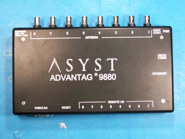
PMQATR9880
Dec 09, 2007RFID Tag Reader/Multiplexer
Equipment Class
DXT - Part 15 Low Power Transceiver, Rx Verified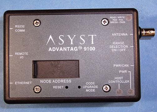
PMQATR9100ROHS
Nov 12, 2006Single Antenna Reader
Equipment Class
DXT - Part 15 Low Power Transceiver, Rx Verified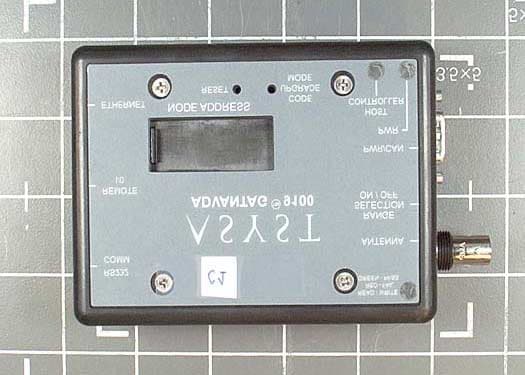
PMQATR9100
Oct 06, 2003Advantag 9100
Equipment Class
DCD - Part 15 Low Power Transmitter Below 1705 kHz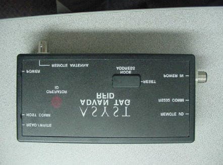
PMQATR9000
Jun 24, 2001ID Tag Reader/Writer Module
Equipment Class
DXT - Part 15 Low Power Transceiver, Rx Verified