PN7MDP-100HDTV Receiving PC Card
Macro Image Technology, Inc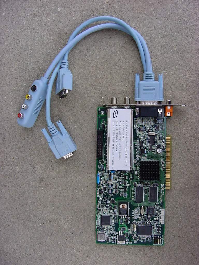
Click to zoom
Application Details
- Equipment Class
- JBP - Part 15 Class B Computing Device Peripheral
- Date of Grant
- Oct 25, 2001
- Application Purpose
- Original Equipment
- Date of Application
- Oct 25, 2001
- Equipment Note
- HDTV Receiving PC Card
- Company
- Macro Image Technology, Inc
- Country
- South Korea
Documents & Files
Document Text
Text extracted from the exhibit documents filed with the FCC. Open a document above to read the original.
Users Manual
i MyHD MDP-100 User’s Guide version 0.9 May, 2001 HDTV PC Card Enjoy digital life with your PC ii FCC INFORMATION TO THE USER This equipment has been tested and found to comply with the limits for a Class B digital device, pursuant to part 15 of the FCC Rules. These limits are designed to provide reasonable protection against harmful interference in a residential installation. This equipment generates, uses and can radiate radio frequency energy and, if not installed and used in accordance with the instructions, may cause harmful interference to radio communications. However, there is no guarantee that interference will not occur in a particular installation. If this equipment does cause harmful interference to radio or television reception, which can be determined by turning the equipment off and on, the user is encouraged to try to correct the interference by one more of the following measures: -. Reorient or relocate the receiving antenna. -. Increase the separation between the equipment and receiver. -. Connect the equipment into an outlet on a circuit different from that to which the receiver is connected. -. Consult the dealer or an experienced radio/TV technician for help. WARNING Changes or modifications not expressly approved by the manufacturer could void the user’s authority to operate the equipment. iii Contents 1.System Requirements ------------------------------------------------------- 1 1.1 PC Platform Requirements ------------------------------------------------ 1 2. Hardware Installation --------------------------------------------------------- 1 2.1 Installation overview --------------------------------------------------------- 1 2.2 Install MyHD card ------------------------------------------------------------- 2 2.3 Connect the Cables ---------------------------------------------------------- 3 2.4 Connecting the MyHD board to a Sound Card ---------------------- 4 2.5 Install the MyHD driver for Windows ------------------------------------- 5 3. Quick Troubleshooting Guide --------------------------------------------- 7 4. MyHD Application ---------------------------------------------------------------- 8 4.1 Application Installation ----------------------------------------------------- 8 4.2 Check lists before running the MyHD --------------------------------- 8 4.3 User Interface Description ------------------------------------------------- 9 4.4 Remote Controller ------------------------------------------------------ 11 4.5 Channel Property Set ------------------------------------------------ 12 4.5.1 Auto Channel Scan ----------------------------------------------------- 12 4.5.2 Change Channel Configure ----------------------------------------- 12 iv 4.5.3 Add/Remove Favorite Channel ------------------------------------- 13 4.5 MyHD Envrionment Configuration -------------------------------------- 14 4.5.1 AV Setup Tab ------------------------------------------------------- 14 4.5.2 VGA Setup Options ---------------------------------------------------- 16 4.7 Pop-up Controls ------------------------------------------------------------ 17 4.8 Keyboard Shortcuts ---------------------------------------------------------- 17 v [blank] MyHD Enjoy digital life with your PC - 1 - Macro Image Technology,Inc. 1. SYSTEM REQUIREMENTS To achieve optimum performance of the MyHD Board, your PC requires a minimum configuration. This chapter provides the system requirements. This chapter contains the following sections: 1.1 PC Platform Requirements The minimum requirements for you PC platform are listed below: CPU : Pentium-II 333MHz or faster DRAM : 64 Megabytes or Higher System Bus : PCI Operating System : Windows 98 Second Edition. , ME Other Software : DirectX Media 6.0 Runtime VGA : DirectX compatibility VGA card (8 MB memory or higher recommended) 2. HARDWARE INSTALLATION The MyHD boards are Plug-and-Play devices designed for Window 98SE and ME. Plug-and-Play simplifies the installation and hardware setup of MyHD by having hardware settings assigned by Windows, instead of needing to set jumpers. This chapter describes how to install these boards and how the automated Plug-and-Play installation procedure works . 2.1 Installation overview To install MyHD under Windows 98SE or ME, you will follow these steps: l Install the MyHD board in your PC l After booting Windows, you will install MyHD’s Windows device driver from the MyHD Installation CD-ROM l After the Windows driver is installed, you will then install the MyHD application software from the MyHD Installation CD-ROM MyHD Enjoy digital life with your PC - 2 - Macro Image Technology,Inc. l Finally, if necessary, an updated Windows Direct X Driver can be installed from the MyHD Installation CD-ROM 2.2 Install MyHD card To install MyHD card, follow the steps listed below: 1. With the power off, remove yo 2. ur computer cover and locate an available PCI slot. 3. Remove the screw attached to the bracket cover and remove the bracket plate. 4. Before handling the MyHD DTVPC card, ground yourself by touching the power supply box inside your computer. 5. Position your card directly above the PCI slot and insert the card firmly into the slot. Care should be taken to press it evenly and snugly into its slot. 6. Once your MyHD DTVPC card is installed properly in its slot, secure it to the computer frame with the screw you removed in step 2. Warning - Static Sensitive Components To avoid possible damage to MyHD DTVPC card and/or other system components from static discharge always discharge your body’s static electricity prior to handling MyHD DTVPC card or other system components. Discharging can be done either by using a properly grounded anti-static wrist strap or by simply touching the chassis of a grounded (plugged-in) computer. In addition, always handle the card by its edges whenever possible, to avoid mechanical damage to delicate components on the board. MyHD Enjoy digital life with your PC - 3 - Macro Image Technology,Inc. …
Text truncated - open the document above for the full version.
Block Diagram
Janus PCI K4S643232C K4S643232C FCV1236 uPC3206 LMV358 NXT2000 VPX3225MSP3440 18.432 MHz 20.250 MHz 50.280 MHz MK2772 13.5 MHz MK2716 27 MHz 74.25 MHz 99 MHz 27 MHz IDT 74FCT 3384 33 MHz Audio Out DS8921PE65612 LT1587 -3.3 LT1587 -ADJ 5V 3.3V2.5V LT1117 -ADJ 12V 9V LT1117 -ADJ 5V VGA IN SPDIF OUT VIDEO OUT 74LVT 541 VIP Out RF in Block Diagram of MDP100 & Clock Path Macro Image Technology Confidential
External Photos
ONETECH Testing & Evaluation Lab. ONETECH Testing & Evaluation Lab.
ID Label/Location Info
FCC ID. : PN7MDP-100 File No. : E015R-054 ONETECH Testing & Evaluation Lab. IDENTIFICATION LABEL: PROPOSED FCC ID LABEL The label included following statement will be attached on the bottom of product. This device complies with Part 15 of the FCC Rules. Operation is subject to the following two conditions: (1) this device may not cause harmful interference, and (2) this device must accept any interference received, including interference that may cause undesired operations. Made in Korea FCC ID : PN7MDP-100 FCC ID AREA
Internal Photos
FCC ID.: PN7MDP-100 File No.: E015R-054 ONETECH Testing & Evaluation Lab. FCC ID.: PN7MDP-100 File No.: E015R-054 ONETECH Testing & Evaluation Lab. FCC ID.: PN7MDP-100 File No.: E015R-054 ONETECH Testing & Evaluation Lab. FCC ID.: PN7MDP-100 File No.: E015R-054 ONETECH Testing & Evaluation Lab.
Test Report
Page 1 of 13 FCC ID. : PN7MDP-100 File No. : E015R-054 This report shall not be reproduced except in full without our written approval. EMC-004 (Rev.0) HEAD OFFICE : #505 SK APT. Factory 223-28, Sangdaewon 1 Dong, Jungwon-Gu, Seongnam-City, Kyunggi-Do, 462-121, Korea (TEL: 82-31-746-8500 FAX: 82-31-746-8700) EMC Testing Dept : 426-1 Daessangryung-Ri, Chowol-Myun, Kwangju-Si, Kyunggi-Do 464-860 Korea. (TEL: 82-31-765-8289 FAX: 82-31-766-2904) ONETECH Testing & Evaluation Lab. ELECTROMAGNETIC EMISSION COMPLIANCE REPORT FOR FCC CLASS B CERTIFICATION Test report file number : E015R-054 Applicant : Macro Image Technology, Inc Address : 723 Yoksam-Dong, Gangnam-Gu, Seoul, 135-080, Korea Manufacturer : Macro Image Technology, Inc Address : 723 Yoksam-Dong, Gangnam-Gu, Seoul, 135-080, Korea Type of Equipment : HDTV Receiving PC Card FCC ID : PN7MDP-100 Model / Type No. : MDP-100 Serial number : N/A Total page of Report : 13 pages (including this page) Date of Incoming : April 12, 2001 Date of issuing : May 29, 2001 SUMMARY The equipment complies with the regulation; FCC CFR 47 PART 15 SUBPART B, Class B. This test report contains only the result of a single test of the sample supplied for the examination. It is not a general valid assessment of the features of the respective products of the mass-production Reviewed by: Approved by: Y. K. Kwon / Chief Engineer S. S. Hong / Managing Director EMC Dept. ONETECH Corp. ONETECH Corp. Page 2 of 13 FCC ID. : PN7MDP-100 File No. : E015R-054 This report shall not be reproduced except in full without our written approval. EMC-004 (Rev.0) HEAD OFFICE : #505 SK APT. Factory 223-28, Sangdaewon 1 Dong, Jungwon-Gu, Seongnam-City, Kyunggi-Do, 462-121, Korea (TEL: 82-31-746-8500 FAX: 82-31-746-8700) EMC Testing Dept : 426-1 Daessangryung-Ri, Chowol-Myun, Kwangju-Si, Kyunggi-Do 464-860 Korea. (TEL: 82-31-765-8289 FAX: 82-31-766-2904) ONETECH Testing & Evaluation Lab. CONTENTS Page 1. VERIFICATION OF COMPLIANCE...............................................................................................................................3 2. GENERAL INFORMATION.................................................................................................................................................4 2.1 PRODUCT DESCRIPTION............................................................................................................................................................4 2.2 RELATED SUBMITTAL(S) / GRANT(S).................................................................................................................................4 2.3 TEST SYSTEM DETAILS..............................................................................................................................................................5 2.4 TEST METHODOLOGY.................................................................................................................................................................5 2.5 TEST FACILITY..............................................................................................................................................................................5 3. SYSTEM TEST CONFIGURATION.................................................................................................................................6 3.1 JUSTIFICATION..............................................................................................................................................................................6 3.2 EUT EXERCISE SOFTWARE......................................................................................................................................................6 3.3 CABLE DESCRIPTION..................................................................................................................................................................6 3.4 NOISE SUPPRESSION PARTS ON CABLE...............................................................................................................................7 3.5 EQUIPMENT MODIFICATIONS.................................................................................................................................................7 3.6 CONFIGURATION OF TEST SYSTEM.......................................................................................................................................7 4. PRELIMINARY TEST...............................................................................................................................................................8 4.1 AC POWER LINE CONDUCTED EMISSION TEST...............................................................................................................8 4.2 RADIATED EMISSION TEST......................................................................................................................................................8 5. FINAL RESULT OF MEASURMENT............................................................................................................................9 5.1 CONDUCTED EMISSION TEST..................................................................................................................................................9 5.2 RADIATED EMISSION TEST....................................................................................................................................................11 6. FIELD STRENGTH CALCULATION..........................................................................................................................12 7. LIST OF TEST EQUIPMENT............................................................................................................................................13 Page 3 of 13 FCC ID. : PN7MDP-100 File No. : E015R-054 This report shall not be reproduced except in full without our written approval. EMC-004 (Rev.0) HEAD OFFICE : #505 SK APT. Factory 223-28, Sangdaewon 1 Dong, Jungwon-Gu, Seongnam-City, Kyunggi-Do, 462-121, Korea…
Text truncated - open the document above for the full version.
Test Setup Photos
ONETECH Testing & Evaluation Lab. ONETECH Testing & Evaluation Lab.
Contact Information
Applicant
S. C Ryu(Researcher)
Test Firm
ONETECH Corp.Y. Kwon
Technical Specifications
| # | Rule Parts | Frequency Range | Power Output |
|---|---|---|---|
| 1 | 15B | - | - |
Other Applications from Macro Image Technology, Inc
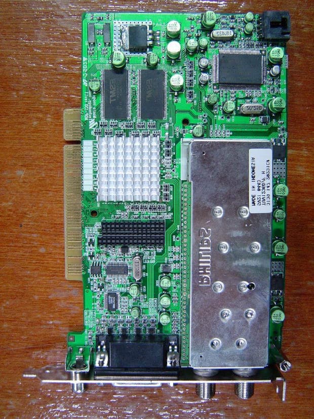
PN7MDP-130
Jan 31, 2005HDTV Receiving PC Card
Equipment Class
JBP - Part 15 Class B Computing Device Peripheral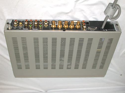
PN7MVS-500
Dec 26, 2002Digital Video Station
Equipment Class
JBP - Part 15 Class B Computing Device Peripheral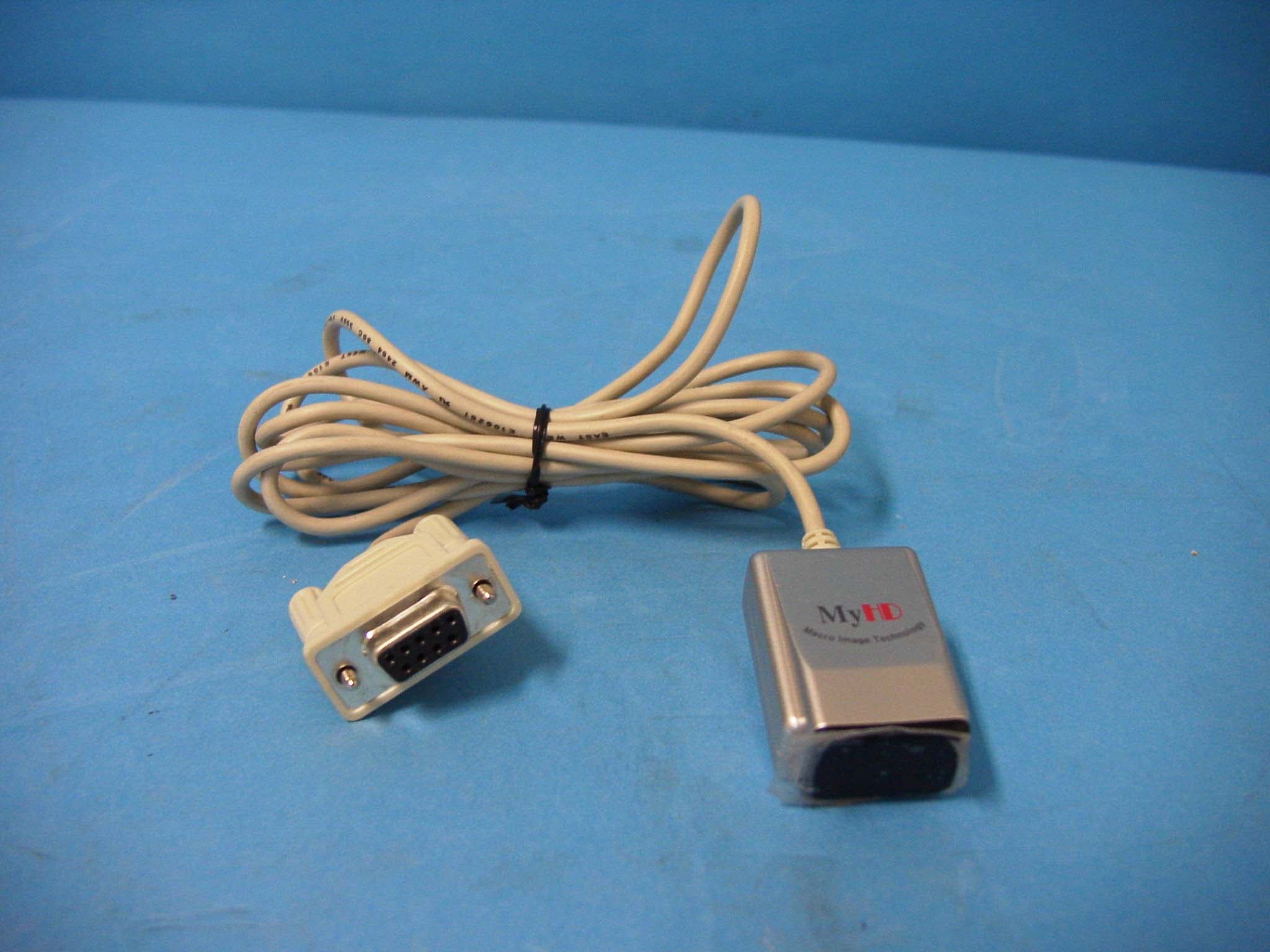
PN7MDP-110L
Jun 02, 2002HD-TV Reception PCI Card
Equipment Class
JBP - Part 15 Class B Computing Device Peripheral