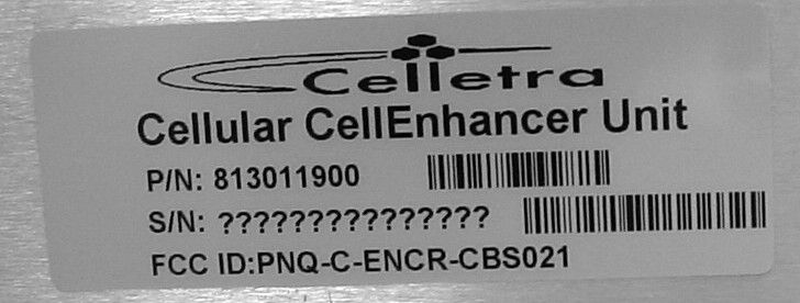
PNQ-C-ENCR-CBS021Cellular CellEnhancer Unit
Celletra Ltd.
Click to zoom
Application Details
- Equipment Class
- AMP - Amplifier
- Date of Grant
- Jun 14, 2004
- Application Purpose
- Original Equipment
- Date of Application
- Jun 14, 2004
- Equipment Note
- Cellular CellEnhancer Unit
- Frequency Range
- 881.00000000 - 881.00000000
- Company
- Celletra Ltd.
- Country
- Israel
Documents & Files
Document Text
Text extracted from the exhibit documents filed with the FCC. Open a document above to read the original.
Users Manual
Cellular Transmission Solutions Document No. 913004500 Rev. 0.0 i Celletra Proprietary Transmit Diversity Add-On System Assembly and Operation Manual October 2003 Document No. 913004500 Rev. 0.0 TDA Unit Document No. 913004500 Rev. 0.0 ii Celletra Proprietary Copyright All data and information contained in or disclosed by this document is confidential and proprietary information of Celletra Ltd and all rights therein are expressly reserved. By accepting this material, the recipient agrees that this material and the information contained therein is held in confidence and in trust and will not be used, copied, reproduced in whole or in part, nor its Contents revealed in any manner to others, without the explicit written permission of Celletra Ltd. Changes are periodically made to the information contained in this manual. These changes are published in the "software/hardware release notes", and will be incorporated into new editions. All rights are reserved. No parts of this manual may be reproduced in any form, without permission in writing from Celletra Ltd. Copyright © 2003, Celletra Ltd. BEAMER Æ is a trademark of Celletra Ltd. Celletra Ltd. reserves the right to change specifications without notice. *All third-party trademarks are the properties of their registered owners. Transmit Diversity Add-On System Assembly and Operation Manual Document No. 913004500 Rev. 0.0 iii Celletra Proprietary Preface • This manual provides instructions for mounting, setting-up, and monitoring Celletraís TDA system. Celletraís TDA system is only for installation indoors or in an outdoor shelter. WARNING Do not expose the TDA equipment to open-air moisture or rain. Record of Changes Change Description Initiated by Date 0 Release Erez Mutzafi October 2003 Repeater Software (TSM) Versions This manual covers the versions of the TDA System Manager (TSM) software version listed below. If your TSM version is not listed, check with Celletra or your Celletra dealer if this manual still applies. If it does, add the version number to this table. TSM Version Date 5.0.0.106 October 2003 Transmit Diversity Add-On System Assembly and Operation Manual Document No. 913004500 Rev. 0.0 iv Celletra Proprietary Safety Information This section describes the use of warnings, cautions, and notes in this manual. It is the userís responsibility to follow all safety instructions and regulations. NOTE: Notes clarify issues. CAUTION This symbol indicates special CAUTION required in a procedure. CAUTION signs prevent actions that may result in equipment malfunction or damage. WARNING WARNING signs prevent actions that may result in harm to personnel. Transmit Diversity Add-On System Assembly and Operation Manual Document No. 913004500 Rev. 0.0 v Celletra Proprietary CAUTION Changes or Modifications not expressly approved by Celletra Ltd. could void the user’s authority to operate the equipment. For customer and technical support, contact www.celletra.com or send an E-mail to [email protected] WARRANTY The following is to inform you that Celletra Ltd. warrants its products as per agreement. Exclusions The warranty (as per the agreement) shall not apply to defects resulting from: improper or inadequate use, unauthorized modifications or misuse. Warranty Limitations Under no circumstances will Celletra Ltd. be liable in any way to the user or any third party for damages, including any loss of profits, lost savings, or other incidental or consequential damages arising out of the use of, or inability to use, the product. Transmit Diversity Add-On System Assembly and Operation Manual Document No. 913004500 Rev. 0.0 vi Celletra Proprietary System Measurement and Testing Warnings WARNING When testing the units in the lab or during field installation, always practice RF radiation safety rules. It is not recommended for service or lab personnel to work closer than two meters from the radiating antenna surfaces when the TDA system operates. CAUTIONS • Disconnect the AC or DC power to the TDA Unit before any cable is connected or disconnected from the unit. • Always use a DC block device connected to the measuring equipment input or output ports (spectrum analyzer, power meter, or RF signal source), when measuring is performed. • Do not connect or disconnect the coaxial connectors while power is applied to the TDA system. • Do not apply more than 0dBm of RF input power to any RF port of the TDA system, or irreversible damage may occur. • When measuring high power outputs, always verify that the equipment input port is capable of handling the expected output power. • During lab or field tests, with AC or DC voltage applied to the TDA Unit, do not use any mobile transmitters in a range of less than 10 meters from the unit. An unexpectedly high RF power might appear at the output ports, which might in turn damage the measuring equipment connected to that port. Transmit Diversity Add-On System Assembly and Operation Manual Document No. 913004500 Rev. 0.0 vii Celletra Proprietary Glossary ABT Active Bias T BTS Base Transceiver Station CDMA Code Division Multiple Access dB Decibel measurement of gain and loss dBm Decibel measurement of power or amplitude, related to 1mW DL Down-link from the donor base station to the mobile users DLDU Down-link Diversity Units FWD forward HP High Power ICU Interface and Control Unit LPA Linear Power Amplifier M&C Monitoring and Control MRC Maximum Ratio Combining MS Mobile Station (cellular phone) mW Milliwatt NOC Network Operating Center PA Power Amplifier PCS Personal Communications Services RF Radio Frequency Rx Receive TD Transmit Diversity TDA Transmit Diversity Add-on TDR Time-Domain Reflectometer TDU Transmit Diversity Units TSM TDA System Manager Tx Transmit Transmit Diversity Add-On System Assembly and Operation Manual Document No. 913004500 Rev. 0.0 viii Celletra Proprietary Table of Contents CHAPTER 1. INTRODUCTION............................................................................................…
Text truncated - open the document above for the full version.
External Photos
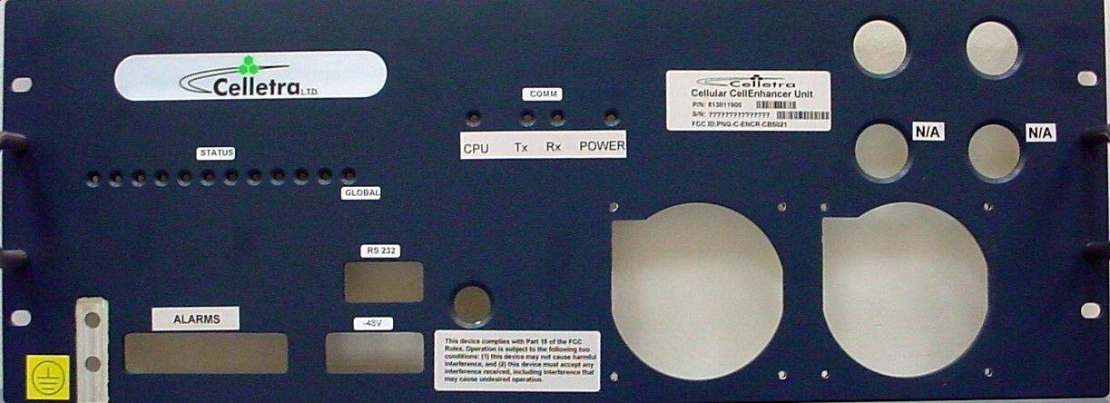
Photographs of Tested E.U.T. Figure 1 Front Panel Figure 2 Internal View Figure 3 PCB 1 Side 1 Figure 4 PCB 1 Side 2 Figure 5 PCB 2 Side 1 Figure 6 PCB 2 Side 2 Figure 7 PCB 3 Side 1 Figure 8 PCB 3 Side 2 Figure 9 PCB 4 Side 1 Figure 10 PCB 4 Side 2 Figure 11. External View
Internal Photos
Photographs of Tested E.U.T. Figure 1 Front Panel Figure 2 Internal View Figure 3 PCB 1 Side 1 Figure 4 PCB 1 Side 2 Figure 5 PCB 2 Side 1 Figure 6 PCB 2 Side 2 Figure 7 PCB 3 Side 1 Figure 8 PCB 3 Side 2 Figure 9 PCB 4 Side 1 Figure 10 PCB 4 Side 2 Figure 11. External View
Operational Description
1.1 About Celletra’s TDA System Celletra Transmit Diversity (TD) technology for CDMA signals enhances the forward link performance by improving the transmit power management, reducing blocking rate, and increasing capacity. The TD technology is available as an add-on to existing (legacy) base stations. In this case, separate components are added to an existing cell site to enhance the performance that can be achieved by the cell site alone on a per-sector basis. This overview of the technology will provide some insights regarding how the TD solution can be applied to a cell site to enhance capacity performance at the site. Add-on Transmit Diversity (TDA) provides for redundant replicas of transmitted signals (from the base station) by transmitting the same information over two or more antennas, providing independently faded channels between the BTS transmit and mobile receive antennas. In order to maintain the total transmitted power (or EIRP), each of the two base station transmit antennas in a TDA system has to transmit a minimum of 50% of the power from a conventional one transmit antenna system. Alternatively, higher power may be transmitted in addition to diversity gain by the two antennas (main and diversity). In this case, the cell footprint in the Down- link will increase, or (after down-tilting the antennas) the same coverage with higher capacity is obtained. The TDA system reduces the per-link-power required for the mobile station (phone). Moreover, reducing the blocking-rate and access-failures improves the cell forward (FWD) link capacity. As a result, in FWD link limited sites, sector erlangs increase. The TD process is carried out only at the base station; no modifications are required at the mobile handset. This gives TDA a clear advantage over other transmit diversity schemes such as OTD and STS which require new chipsets to be included in the mobile handset. 1.2 TDA System Description 1.2.1 Block Diagram Figure 1-1 describes the TDA system. 1.2.2 General Description The Celletra TDA system consists of the TDA Unit and Coupler: The TDA Unit interfaces transparently to the BTS at RF low-power levels. The TDA Unit generates the Transmit Diversity (TD) signals and power-amplifies the TD signals to be transmitted through the Tx-Diversity antenna.
Test Report
Cert. No. 1152.01 Electrical (EMC) Test Report E53391.01 Celletra Ltd. Page 1 of 60 FCC ACC M Ver 1.1 05Mayl 2000 DATE: 03 June 2004 I.T.L. (PRODUCT TESTING) LTD. FCC EMC Test Report for Celletra Ltd. Equipment under test: Cellular CellEnhancer Unit (TDA) 813011900 Written by: _____________________________ D. Shidlowsky, Documentation Approved by: _____________________________ E. Pitt, Test Engineer Approved by: _____________________________ I. Raz, EMC Laboratory Manager This report must not be reproduced, except in full, without the written permission of I.T.L. (Product Testing) Ltd. This report relates only to items tested. Cert. No. 1152.01 Electrical (EMC) Test Report E53391.01 Celletra Ltd. Page 2 of 60 FCC ACC M Ver 1.1 05Mayl 2000 Measurement/Technical Report for Celletra Ltd. Cellular CellEnhancer Unit (TDA) (For Transmitter Section) 813011900 FCC ID:PNQ-C-ENCR-CBS021 03 June 2004 This report concerns: Original Grant x Class II change Class B verification Class A verification Class I change Equipment type: Cellular CellEnhancer Unit (TDA) FCC Form 731 Class: AMP Request Issue of Grant: x Immediately upon completion of review Limits used: CISPR 22 Parts 15; 22 x Measurement procedure used is ANSI C63.4-2001. Substitution Method used as in ANSI/TIA-603-B: 2002 Application for Certification Applicant for this device: prepared by: (different from "prepared by") Ishaishou Raz Ram Dishon ITL (Product Testing) Ltd. Celletra Ltd. Kfar Bin Nun P.O.B. 106, Tavor Building D.N. Shimshon 99780 Yoqne’am, 20692 Israel Israel e-mail [email protected] Tel: +972-4-959-2522 Fax: +972-4-959-2523 e-mail: [email protected] Test Report E53391.01 Celletra Ltd. Page 3 of 60 FCC ACC M Ver 1.1 05Mayl 2000 TABLE OF CONTENTS 1. GENERAL INFORMATION ------------------------------------------------------------------------------- 5 1.1 Administrative Information.................................................................................5 1.2 List of Accreditations .........................................................................................6 1.3 Product Description ...........................................................................................7 1.4 Test Methodology..............................................................................................7 1.5 Test Facility .......................................................................................................7 1.6 Measurement Uncertainty .................................................................................7 2. PRODUCT LABELING ------------------------------------------------------------------------------------ 8 3. SYSTEM TEST CONFIGURATION--------------------------------------------------------------------- 9 3.1 Justification........................................................................................................9 3.2 EUT Exercise Software .....................................................................................9 3.3 Special Accessories ..........................................................................................9 3.4 Equipment Modifications ...................................................................................9 3.5 Configuration of Tested System ......................................................................10 4. BLOCK DIAGRAM-----------------------------------------------------------------------------------------11 4.1 Schematic Block/Connection Diagram............................................................11 4.2 Theory of Operation ........................................................................................11 5. EFFECTIVE RADIATED POWER----------------------------------------------------------------------12 5.1 Test procedure ................................................................................................12 5.2 Results table....................................................................................................13 5.3 Test Equipment Used......................................................................................13 6. OCCUPIED BANDWIDTH -------------------------------------------------------------------------------14 6.1 Test Procedure................................................................................................14 6.2 Results Table ..................................................................................................15 6.3 Test Equipment Used......................................................................................16 7. OUT OF BAND EMISSIONS (RADIATED) ----------------------------------------------------------17 7.1 Test Specification ............................................................................................17 7.2 Test Procedure................................................................................................17 7.3 Test Data .........................................................................................................18 7.4 Test Instrumentation Used, Radiated Measurements ....................................20 8. OUT OF BAND EMISSIONS AT ANTENNA TERMINALS --------------------------------------21 8.1 Test procedure ................................................................................................21 8.2 Results table....................................................................................................25 8.3 Test Equipment Used......................................................................................26 9. RADIATED EMISSION, PER FCC PART 15--------------------------------------------------------27 9.1 Test Specification ............................................................................................27 9.2 Test Procedure................................................................................................27 9.3 Test Data .........................................................................................................28 9.4 Test Instrumenta…
Text truncated - open the document above for the full version.
Test Report
Chris Harvey From: EMC [[email protected]] Sent: Wednesday, June 02, 2004 5:07 AM To: Chris Harvey Subject: RE: MT#15588 ITL Celletra Application for Certification Page 1 of 2 6/2/2004 Hi Chris, 1. Section 2 of of your email below: Attached is Celletra's confirmation that the product uses 881MHz CDMA channel only. 2. Section 3 in your email: According to Celletra's information: 2.1. AC/DC voltages and currents: The final amplifying device draws 6A from 27VDC at rated power. 2.2. Tune-up procedure: T.B.D. 2.3. Parts List See attached file. 3. I'll try to complete the response to your other comments A.S.A.P. 4. David had trouble finding the Public Notice mentioned in your email of 02 June 2004. Can you send us the document no. so we can download it? Best regards Shaike Raz EMC Laboratory Manager EMC Laboratory ITL (Product Testing) Ltd. Kfar Bin Nun Israel Tel: +972-8-9797799 Fax: +972-8-9797702 Email: [email protected] http://www.itl.co.il http://www.i-spec.com This e-mail message may contain privileged or confidential information. If you are not the intended recipient, you may not disclose, use, disseminate, distribute, copy or rely upon this message or attachment in any way. If you received this e-mail message in error, please return by forwarding the message and its attachments to the sender. -----Original Message----- From: Chris Harvey [mailto:[email protected]] Sent: Wednesday, May 26, 2004 6:25 PM To: EMC; Shaike Raz Cc: 'Marianne Bosley'; [email protected] Subject: MT#15588 ITL Celletra Application for Certification David and Shaike, I have started reviewing the TCB and IC applications for Celletra and have the following items that need to be addressed: 1) Test Report page 5 of 56 shows FCC Pt. 15 Subpart C, which should probably reference FCC Pt. 22. 2) Please confirm that this device only operates on the single 881MHz CDMA channel. The applications as filed would only result in authorizations at that single channel of 881MHz using CDMA modulation. 3) Please provide exhibits to satisfy the folling FCC requirements: DC voltages and Currents 2.1033 (c)(8) Tune-up Procedure 2.1033(c)(9) Parts list 2.1033(c) 4) The Radiated Spurious emissions are to be measured in accordance with the substitution method of TIA/EIA- 603. Please verify that this device complies with the requirements for Fieldstrength of Spurious Emissions using the substitution method. 5) The Radio Equipment Listing Acknowledgement and Cross Reference Table indicate that the standard utilized was RSS-118. This device is a ‘Zone Enhancer’ which should be tested in accordance RSS-131 (copy attached). Please provide confirmation of compliance with RSS-131 and corrected exhibits. 6) Please provide a completed Test Report Cover Sheet for IC Certification in accordance with RSP-100. Please respond to me at both addresses listed above (reply all) so that I can continue the application review. Best regards, Chris Harvey Page 2 of 2 6/2/2004
Test Report
Chris Harvey From: Ram Dishon [[email protected]] Sent: Tuesday, June 01, 2004 11:57 AM To: EMC Cc: David Cahana Subject: RE: FCC/Industry Canada Certification for Cellular CellEnhancer Page 1 of 3FCC/Industry Canada Certification for Cellular CellEnhancer 6/2/2004 Shalom Shaike, I have discussed the issue in section 2 with all parties concerned. The device operates on a single, 881MHz CDMA channel only. Best Regards, Ram Dishon. -----Original Message----- From: EMC [mailto:[email protected]] Sent: Tuesday, June 01, 2004 4:52 PM To: Ram Dishon Subject: RE: FCC/Industry Canada Certification for Cellular CellEnhancer Shalom Ram, 1. Attached is the message received from the TCB. Please refer to Section 2. 2. According to the information that you gave us prior to testing, you requested to test specifically using a 881MHz carrier and CDMA modulation as representing the actual operating conditions. 3. According to the reply that we received in your email below, other carriers within the block may be used by your product. Please clarify. Regards Shaike Raz EMC Laboratory Manager EMC Laboratory ITL (Product Testing) Ltd. Kfar Bin Nun Israel Tel: +972-8-9797799 Fax: +972-8-9797702 Email: [email protected] http://www.itl.co.il http://www.i-spec.com This e-mail message may contain privileged or confidential information. If you are not the intended recipient, you may not disclose, use, disseminate, distribute, copy or rely upon this message or attachment in any way. If you received this e-mail message in error, please return by forwarding the message and its attachments to the sender. -----Original Message----- From: Ram Dishon [mailto:[email protected]] Sent: Monday, May 31, 2004 3:39 PM To: EMC Subject: RE: FCC/Industry Canada Certification for Cellular CellEnhancer Shalom Shaike, See herein answers to your items 1-4 and attached parts list. In response to the TCB/CCB review, we need A.S.A.P. the following information: 1. Confirm that the device only operates on the single 881MHz CDMA channel. [David Cahana] The device is specified to operate in the Cellular B-Block, 880-890 MHz. 2. State the nominal bandwidth of the product. [David Cahana] The nominal bandwidth is 10 MHz, but at any given time it will amplify just one CDMA carrier of 1.25 MHz bandwidth 3. Levels of DC voltage and current applied to the RF final amplifying device at rated power (Section 2.1033 (c) (8) of Part 2). [David Cahana] The final amplifying device draws 6 A from +27 Vdc 4. Information concerning tune-up procedure over the power range, or at specific operating power levels (Section 2.1033 (c) (9) of Part 2). [David Cahana] The tune up procedure amounts to an adjustment of the amplifier gain to equate the output power with that of another power amplifier path. The gain adjustment is achieved by digitally controlling a RF variable attenuator. 5. Parts List. See Attached. Best Regards, Ram Dishon. -----Original Message----- From: EMC [mailto:[email protected]] Sent: Monday, May 31, 2004 10:49 AM To: Ram Dishon (E-mail) Subject: FCC/Industry Canada Certification for Cellular CellEnhancer Shalom Ram, In response to the TCB/CCB review, we need A.S.A.P. the following information: 1. Confirm that the device only operates on the single 881MHz CDMA channel. 2. State the nominal bandwidth of the product. 3. Levels of DC voltage and current applied to the RF final amplifying device at rated power (Section 2.1033 (c) (8) of Part 2). 4. Information concerning tune-up procedure over the power range, or at specific operating power levels (Section 2.1033 (c) (9) of Part 2). 5. Parts List. Thank you for your assistance Regards Shaike Raz EMC Laboratory Manager EMC Laboratory ITL (Product Testing) Ltd. Kfar Bin Nun Israel Tel: +972-8-9797799 Fax: +972-8-9797702 Email: [email protected] http://www.itl.co.il http://www.i-spec.com Page 2 of 3FCC/Industry Canada Certification for Cellular CellEnhancer 6/2/2004 This e-mail message may contain privileged or confidential information. If you are not the intended recipient, you may not disclose, use, disseminate, distribute, copy or rely upon this message or attachment in any way. If you received this e-mail message in error, please return by forwarding the message and its attachments to the sender. Page 3 of 3FCC/Industry Canada Certification for Cellular CellEnhancer 6/2/2004
Test Report
Chris Harvey From: EMC [[email protected]] Sent: Sunday, June 06, 2004 4:45 AM To: Chris Harvey Subject: RE: MT#15588 ITL Celletra Application for Certification Page 1 of 2RE: MT#15588 ITL Celletra Application for Certification 6/6/2004 Hi Chris, 1. Thank you for your response. 2. Attached is the revised report including the changes resulting from your comments. 3. A response to Section 3 (Tune-up Procedure) in your May 26, 2004 email will be sent by tomorrow morning. Regards Shaike Raz EMC Laboratory Manager EMC Laboratory ITL (Product Testing) Ltd. Kfar Bin Nun Israel Tel: +972-8-9797799 Fax: +972-8-9797702 Email: [email protected] http://www.itl.co.il http://www.i-spec.com This e-mail message may contain privileged or confidential information. If you are not the intended recipient, you may not disclose, use, disseminate, distribute, copy or rely upon this message or attachment in any way. If you received this e-mail message in error, please return by forwarding the message and its attachments to the sender. -----Original Message----- From: Chris Harvey [mailto:[email protected]] Sent: Thursday, June 03, 2004 8:28 PM To: EMC Subject: RE: MT#15588 ITL Celletra Application for Certification I understand the expense of the standards. Hopefully this standard will pay off in growing wireless business for you. Please revise the report using this 603 method. Best regards, Chris Harvey -----Original Message----- From: EMC [mailto:[email protected]] Sent: Thursday, June 03, 2004 9:10 AM To: Chris Harvey (E-mail) Cc: Chris Harvey (E-mail 3) Subject: RE: MT#15588 ITL Celletra Application for Certification Ref: Your email of May 26 2004 <<MT#15588 ITL Celletra Application for Certification>> Hi Chris, Concerning Section 4 in your above referenced email: 1. We purchased the ANSI/TIA-603-B: 2002 standard ($211!!) and reviewed its test method (very similar to ETSI's method). We performed a re-test at antenna height of 0.8m for the substitution step (instead of 1.5m height for the ETSI method). 2. The new result is 4.1dB higher, still 19.6dB below the limit (-13dBm). 3. If the above is acceptable (please advise), I'll email to you all the applicable revised pages of the FCC report. Regards Shaike Raz EMC Laboratory Manager EMC Laboratory ITL (Product Testing) Ltd. Kfar Bin Nun Israel Tel: +972-8-9797799 Fax: +972-8-9797702 Email: [email protected] http://www.itl.co.il http://www.i-spec.com This e-mail message may contain privileged or confidential information. If you are not the intended recipient, you may not disclose, use, disseminate, distribute, copy or rely upon this message or attachment in any way. If you received this e-mail message in error, please return by forwarding the message and its attachments to the sender. Page 2 of 2RE: MT#15588 ITL Celletra Application for Certification 6/6/2004
Contact Information
Applicant
Gideon Argaman(GVP & CIO)
Test Firm
ITL Product Testing LTDSteli Loznen
Technical Specifications
| # | Rule Parts | Frequency Range | Power Output | Emission | Tolerance |
|---|---|---|---|---|---|
| 1 | 22H | 881 MHz - 881 MHz | 17.5 W | F1W | ppm |
Other Applications from Celletra Ltd.

PNQC-MP1-M1
Dec 22, 2002PCS Beamer
Equipment Class
AMP - Amplifier
PNQC-EP2-NW
Nov 20, 2002Single Carrier CDMA PCS Apmlifier
Equipment Class
AMP - Amplifier
PNQC-UPB
Sep 08, 2002Single Channelized PCS Beamer Amplifier Unit
Equipment Class
AMP - Amplifier
PNQC-CPB
Sep 08, 2002Single Channelized PCS Coverage Enlightener Beamer
Equipment Class
AMP - Amplifier
PNQC-BCL
Dec 06, 2001Cellular Multi-Channel Amplifier Antenna
Equipment Class
AMP - Amplifier