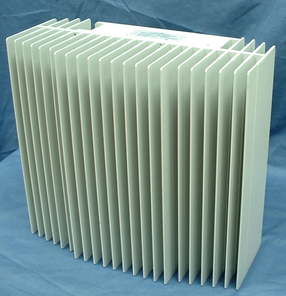
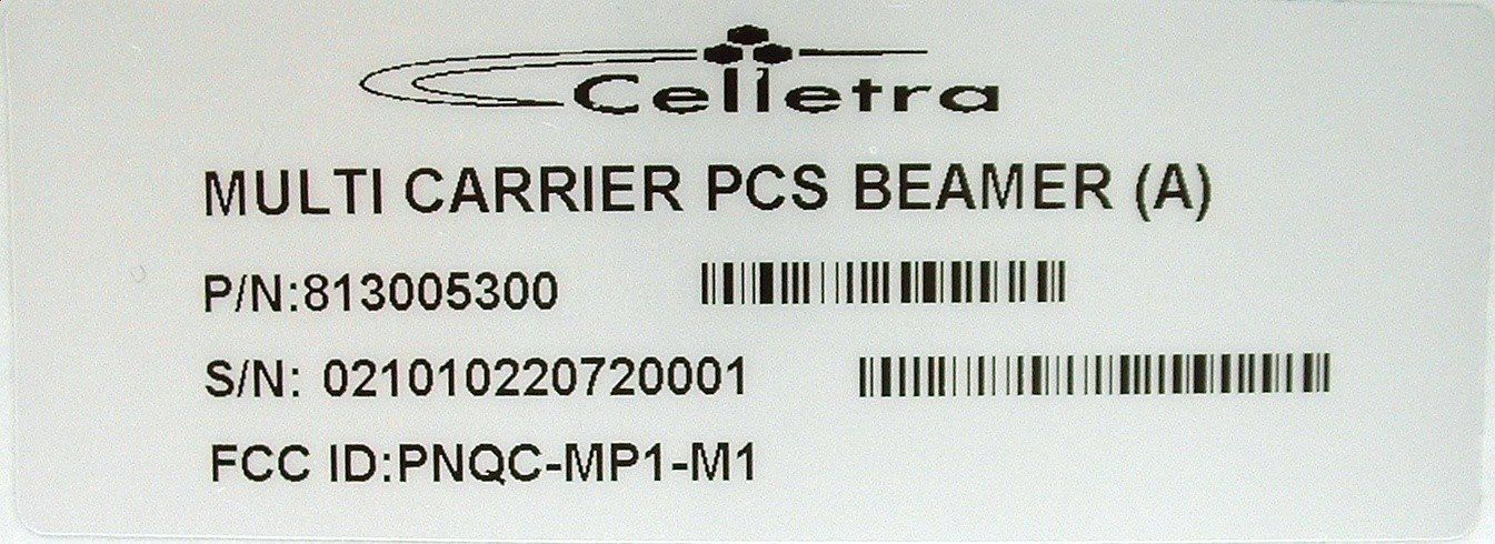
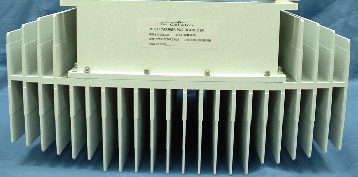
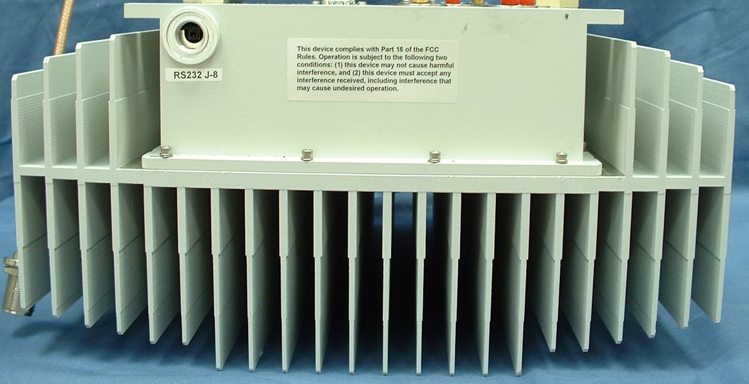
PNQC-MP1-M1PCS Beamer
Celletra Ltd.
Click to zoom
Application Details
- Equipment Class
- AMP - Amplifier
- Date of Grant
- Dec 22, 2002
- Application Purpose
- Original Equipment
- Date of Application
- Dec 22, 2002
- Equipment Note
- PCS Beamer
- Frequency Range
- 1850.00000000 - 1910.00000000
- Company
- Celletra Ltd.
- Country
- Israel
Documents & Files
Document Text
Text extracted from the exhibit documents filed with the FCC. Open a document above to read the original.
Users Manual
Cellular Transmission Solutions P.O.Box 106, Tavor building 1 Yoqne’am Ilit 20692, ISRAEL Tel. + 972 4 9592522 Fax. + 972 4 9592523 E-mail: [email protected] 1 Multicarrier PCS Beamer Concise User-Guide No. 913002900 Multicarrier PCS Beamer Concise User-Guide Document No. 913002900 Name Date Signature Written By David C. Checked G. Argaman Cellular Transmission Solutions P.O.Box 106, Tavor building 1 Yoqne’am Ilit 20692, ISRAEL Tel. + 972 4 9592522 Fax. + 972 4 9592523 E-mail: [email protected] 2 Multicarrier PCS Beamer Concise User-Guide No. 913002900 FCC Part 15A Compliance Statement This device complies with part 15 of the FCC rule. Operation is subject to the following two conditions: (1) this device may not cause harmful interference , and (2) this device must accept any interference received , including interference that may cause undesired operation Caution Changes or Modifications not expressly approved by Celletra Ltd. could void the user’s authority to operate the equipment” NOTE This equipment has been tested and found to comply with the limits for a Class A digital device, pursuant to part 15 of the FCC rules. These limits are designed to provide reasonable protection against harmful interference when the equipment is operated in a commercial environment. This equipment generates, uses, and can radiate Radio Frequency energy and, if not installed and used in accordance with the instructions manual, may cause harmful interference to radio communication. Operation of this equipment in a residential area is likely to cause harmful interference in which case the user will be required to correct the interference at his own expense. Cellular Transmission Solutions P.O.Box 106, Tavor building 1 Yoqne’am Ilit 20692, ISRAEL Tel. + 972 4 9592522 Fax. + 972 4 9592523 E-mail: [email protected] 3 Multicarrier PCS Beamer Concise User-Guide No. 913002900 Multicarrier PCS Beamer Concise User-Guide 1. Connect the RS232 adapter to the Beamer on one side and to the laptop computer on the other side. The connection to the Beamer is done with the supplied stereo cable , which is plugged into port J8 of the Beamer. The connection to the laptop is done with the RS232 connector. See the Beamer block diagram in Figure 6. 2. Connect J9 – the N-connector at the end of the Diplexer antenna cable - to a 50Watt load via a directional coupler. Alternatively, connect a 50Watt 30 dB attenuator. 3. To test the Transmit path, connect the CDMA signal source to J1 – the Tx Input connector. The signal level should initially be about –20 dBm to ensure a deep backoff operating point, which is at least 10 dB lower than the nominal. 4. Connect the supplied DC cable to port J7 on the Beamer. Connect the other end to a 24VDC power supply with a rating of at least 10 A. To prevent damage to the unit under test make sure that the power supply is not current-limited. The current consumption should be in the range of 3-4 A. 5. On the laptop Desktop, click on the shortcut icon of Rx_Test_2, a HPVEE user-interface program. The window in Figure 1 will open up. 6. Select PCS and clock OK. The window in Figure 2 will open up, except that the Unit ID number, on the upper-left corner of the window, will not be displayed yet. 7. Click on F1: Unit ID , on the top left corner and the window in Figure 3 will open up. 8. On the right side of this window a smaller “Select variable !” window will open up. Select “Read Unit id” and click OK. The Unit ID number will be displayed in the first row of the Unit Status column on the upper-left corner of the main window, as shown in Figure 2. The display of the Unit ID confirms communication with the Beamer. 9. To monitor the Beamer click on “Unit status” which is located in the lower-left part of the main window. The window in Figure 4 will open up. The following readings are displayed along the left- side of the main window: a. Temp: The second number, after the comma, displays the internal temperature in 0 C b. In power: Input power as calibrated with three CDMA carriers c. Out power: Output power as calibrated with three CDMA carriers d. Tx, Rx Att’: State of the variable attenuators of the Tx and Main Rx paths, respectively, in dB. Display of the Diversity Rx path attenuation is not yet supported. 10. The HPVEE user interface does not support alarm indications. However, the Beamer is self- protected in the event of: a. Overtemperature: Shuts off at 85 0 C and resets at 65 0 C. b. Overpower: Shuts off at 43 dBm three CDMA carrier output power. c. Overcurrent: Shuts off at current equivalent to 43 dBm three CDMA carrier output power. 11. For nominal operation, the input signal level to the Beamer should be about -6 dBm. The typical DC consumption under this condition is 6-6.5 A @ 24 VDC input. 12. To disable the Tx power amplifier click on the Tx Amp toggle-switch , located in the lower- left area of the main window. Cellular Transmission Solutions P.O.Box 106, Tavor building 1 Yoqne’am Ilit 20692, ISRAEL Tel. + 972 4 9592522 Fax. + 972 4 9592523 E-mail: [email protected] 4 Multicarrier PCS Beamer Concise User-Guide No. 913002900 13. To test the Main Rx path, disconnect J9, the Diplexer antenna connector, from the loads of the Tx test and connect J9 to a –30 dBm signal source. Connect J3, the Main Rx Out port, to the appropriate test load, e.g. spectrum analyzer. 14. To test the Diversity Rx path, connect J6, the Rx Diversity In port to the –30 dBm signal source and J5, the Rx Diversity Out port, to the test load. 15. To change the gain setting of any path, click on F4: Main Rx Attenuator, F5: Div. Rx Attenuator, or on F6: Tx Attenuator, as appropriate. In each case, a slide control will open up as illustrated in Figure 5. The slide can be moved by either sliding the Mouse over it or clicking on the Inc+ or Dec – buttons. When the desired attenuation is set click OK in the same window . The gain control range is 15.5 dB in 0.5 dB steps. Figure 1 Cellular Transmission Solution…
Text truncated - open the document above for the full version.
Cover Letter(s)
Cellular Transmission Solutions P.O.Box 106, Tavor building 1 Yoqne’am Ilit 20692, ISRAEL Tel. + 972 4 9592522 Fax. + 972 4 9592523 E-mail: celletra @celletra.com 1 October 24, 2002 attn: Reviewing Engineer Federal Communications Commission 7435 Oakland Mills Road Columbia, MD 21046 RE: LETTER OF AGENT AUTHORIZATION To Whom It May Concern: The undersigned, Celletra Ltd., hereby authorizes MET Laboratories, Inc. to act on our behalf with regard to the application for a FCC Type Approval equipment authorization, including the signing and execution of all documents relating to these matters. We also hereby certify that no party to the application authorized hereunder is subject to the denial of benefits, including FCC benefits, pursuant to Section 5301 of the Anti-Drug Abuse Act of 1988,21 U.S.C.853 (a). This agreement expires one year from the date hereunder. Sincerely, Gideon Argaman CTO Celletra Ltd. P.O. Box 106, Yoqne’am, 20692 Israel October 24 th , 2002
Parts List/Tune Up Info
Tuneup Procedure - Past Factory tuning, Customer tuneup is not required.
Test Report
The Nation's First Licensed Nationally Recognized Testing Laboratory Conceil canadien des nomes Organisme de certification accedite Standards Council of Canada Accredited Certification Organization TM MET Laboratories, Inc. Safety Certification - EMI - Telecom Environmental Simulation 914 WEST PATAPSCO AVENUE !! BALTIMORE, MARYLAND 21230-3432 !! PHONE (410) 354-3300 !! FAX (410) 354-3313 December 20, 2002 Celletra. P.O. Box 106 Tavor Building Yoque’am Ilit ISRAEL Reference:Multicarrier PCS Beamer (A) FCC ID: PNQC-MP1-M1 Dear Mr. Gideon Argaman: Enclosed is the EMC Test Report for the Celletra Multicarrier PCS Beamer (A). The Celletra Multicarrier PCS Beamer (A) was tested to the requirements of the FCC Rules and Regulations, Part 24 Subpart E, of Title 47 of the CFR, for a PCS Repeater. Thank you for using the testing services of MET Laboratories. If you have any questions regarding these results or if MET can be of further assistance to you, please feel free to contact me. We appreciate your business and look forward to working with you again soon. Kindest Regards, MET LABORATORIES, INC. Marianne T. Bosley EMC Administrator Enclosures: (\Celletra\EMC12938B-FCC24.rpt) DOCTEM-23 Jan 02 Certificates and reports shall not be reproduced except in full, without the written permission of MET Laboratories, Inc. While use of the National Voluntary Laboratory Accreditation Program (NVLAP) letters or the NVLAP Logo in this report reflects the MET Accreditation under the NVLAP Program, these letters, logo, or Statements do not claim product endorsement by NVLAP or any Agency of the U.S. Government. CelletraMulticarrier PCS Beamer (A)FCC ID: PNQC-MP1-M1December 20, 2002 Electro-Magnetic Compatibility Test Report for the Celletra Multicarrier PCS Beamer (A) Tested Under FCC Part 24, Subpart E Title 47 of the CFR for Broadband PCS Devices MET REPORT: EMC12938B-FCC24 August 21, 2002 PREPARED FOR: Celletra P.O. Box 106 Tavor Building Yoque’am Ilit ISRAEL PREPARED BY: MET Laboratories, Inc. 914 West Patapsco Avenue Baltimore, Maryland 21230-3432 Copyright 2003, MET Laboratories, Inc. This report shall not be reproduced except in full, without the express written consent of MET Laboratories, Inc., nor shall this report, or any copy thereof be provided to a competitor of MET Laboratories, Inc. CelletraMulticarrier PCS Beamer (A)FCC ID: PNQC-MP1-M1December 20, 2002 Page i of vi MET REPORT: EMC12938B-FCC24Copyright 2002, MET Laboratories, Inc. Electro-Magnetic Compatibility Test Report for the Multicarrier PCS Beamer (A) Tested Under FCC Part 24 Subpart E Title 47 of the CFR for Broadband PCS Devices MET REPORT: EMC12938B-FCC24 PREPARED FOR: Celletra P.O. Box 106 Tavor Building Yoque’am Ilit ISRAEL _______________________________ Christopher R. Harvey, Director Electromagnetic Compatibility Testing _______________________________ Marianne T. Bosley EMC Administrator Engineering Statement: The measurements shown in this report were made in accordance with the procedures indicated, and the emissions from this equipment were found to be within the limits applicable. I assume full responsibility for the accuracy and completeness of these measurements, and for the qualifications of all persons taking them.. It is further stated that upon the basis of the measurements made, the equipment tested is capable of operation in accordance with the requirements of Part 24, Subpart E, of the FCC Rules under normal use and maintenance. _______________________________ Liming Xu Project Engineer CelletraMulticarrier PCS Beamer (A)FCC ID: PNQC-MP1-M1December 20, 2002 Page ii of vi MET REPORT: EMC12938B-FCC24Copyright 2002, MET Laboratories, Inc. REPORT STATUS SHEET RevisionReport/ Revision DateReason for Revision iNovember 11, 2002 Initial Draft Issue. 1December 20, 2002Final Report Issue CelletraMulticarrier PCS Beamer (A)FCC ID: PNQC-MP1-M1December 20, 2002 Page iii of vi MET REPORT: EMC12938B-FCC24Copyright 2002, MET Laboratories, Inc. TABLE OF CONTENTS I.Executive Summary.......................................................................1 A.Purpose of Test.............................................................2 B.Executive Summary.........................................................2 IIGeneral................................................................................3 A.Test Site..................................................................4 B.Description of Test Sample....................................................4 C.General Test Setup..........................................................4 D.Mode of Operation..........................................................4 E.Antenna Specifications.......................................................7 F.Modifications..............................................................7 G.Disposition of Test Sample....................................................7 III.RF Power Output Requirements..............................................................8 IV.Occupied Bandwidth Requirements .........................................................14 V.Emissions Requirements ..................................................................18 A.Spurious Emissions at Antenna Terminals (Uplink & Downlink)......................19 B.Intermodulation Spurious Emissions at Antenna Terminals (Uplink & Downlink).........25 C.Radiated Emissions........................................................28 VI. Test Equipment.........................................................................29 VII. Certification Label & User's Manual Information................................................31 A.Certification Information....................................................32 B.Label and User's Manual Information...........................................34 CelletraMulticarrier PCS Beamer (A)FCC ID: PNQC-MP1-M1December 20, 2002 Page iv of vi MET REPORT: EMC12938B-FCC24Copyright 2002, MET Laboratories, Inc. List of Tables Table 1.Summary of Test Results.......…
Text truncated - open the document above for the full version.
Contact Information
Applicant
Gideon Argaman(GVP & CIO)
Test Firm
MET Laboratories, Inc.John Mason
Technical Specifications
| # | Rule Parts | Frequency Range | Power Output | Emission | Tolerance |
|---|---|---|---|---|---|
| 2 | 24 | 1.85 GHz - 1.91 GHz | 1.00 mW | F9W | Amp |
Other Applications from Celletra Ltd.

PNQ-C-ENCR-CBS021
Jun 14, 2004Cellular CellEnhancer Unit
Equipment Class
AMP - Amplifier
PNQC-EP2-NW
Nov 20, 2002Single Carrier CDMA PCS Apmlifier
Equipment Class
AMP - Amplifier
PNQC-UPB
Sep 08, 2002Single Channelized PCS Beamer Amplifier Unit
Equipment Class
AMP - Amplifier
PNQC-CPB
Sep 08, 2002Single Channelized PCS Coverage Enlightener Beamer
Equipment Class
AMP - Amplifier
PNQC-BCL
Dec 06, 2001Cellular Multi-Channel Amplifier Antenna
Equipment Class
AMP - Amplifier