PNQC-BPBPCS Multi-Channel Amplifier Antenna
Celletra Ltd.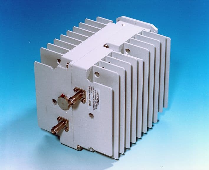
Click to zoom
Application Details
- Equipment Class
- AMP - Amplifier
- Date of Grant
- Aug 23, 2001
- Application Purpose
- Original Equipment
- Date of Application
- Aug 23, 2001
- Equipment Note
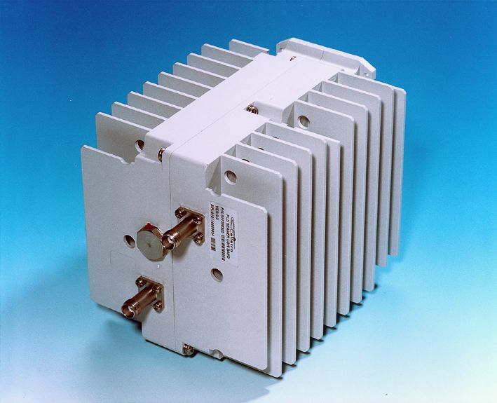
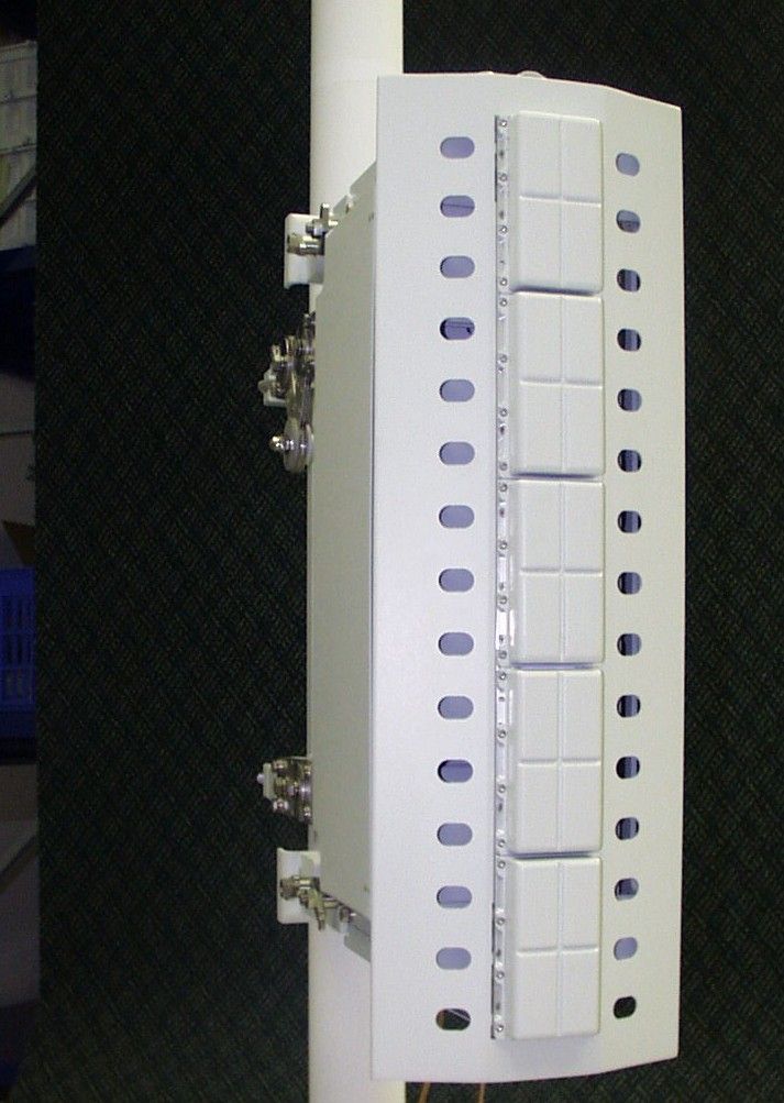
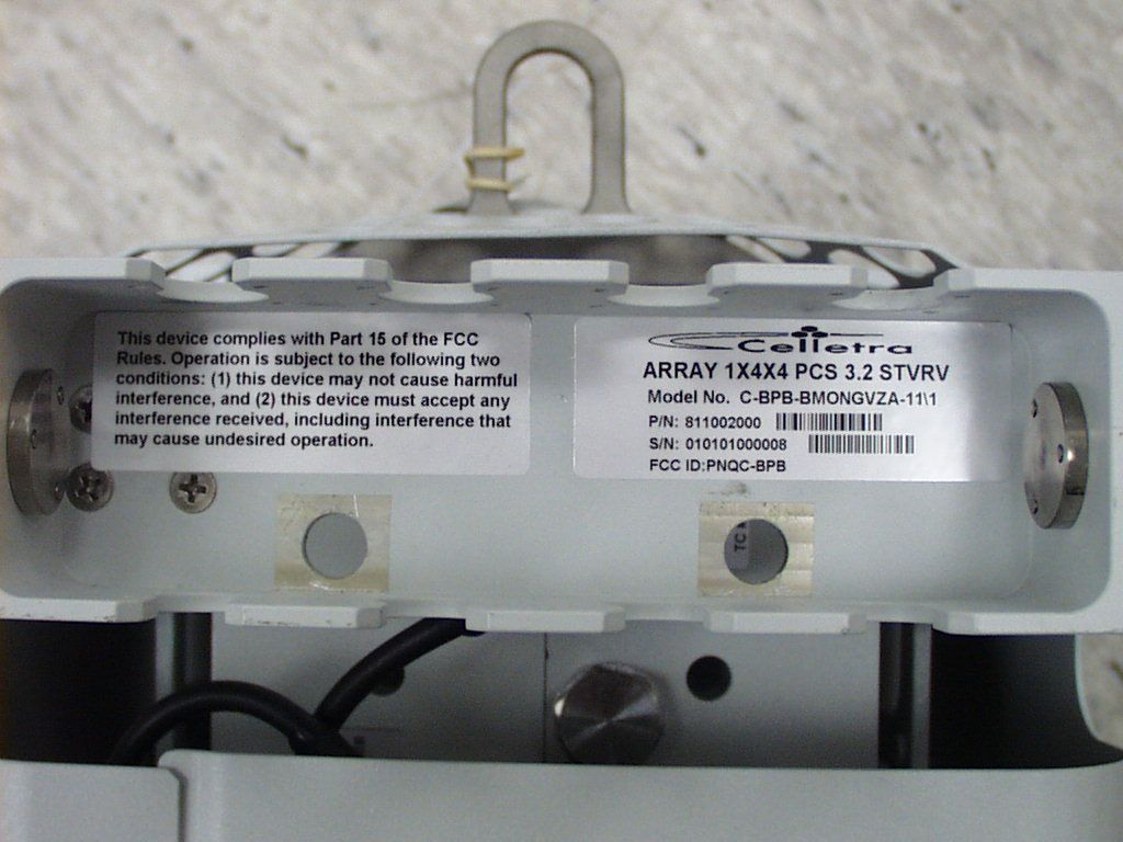
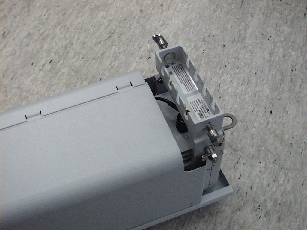
- PCS Multi-Channel Amplifier Antenna
- Frequency Range
- 1930.00000000 - 1990.00000000
- Company
- Celletra Ltd.
- Country
- Israel
Documents & Files
Document Text
Text extracted from the exhibit documents filed with the FCC. Open a document above to read the original.
Users Manual
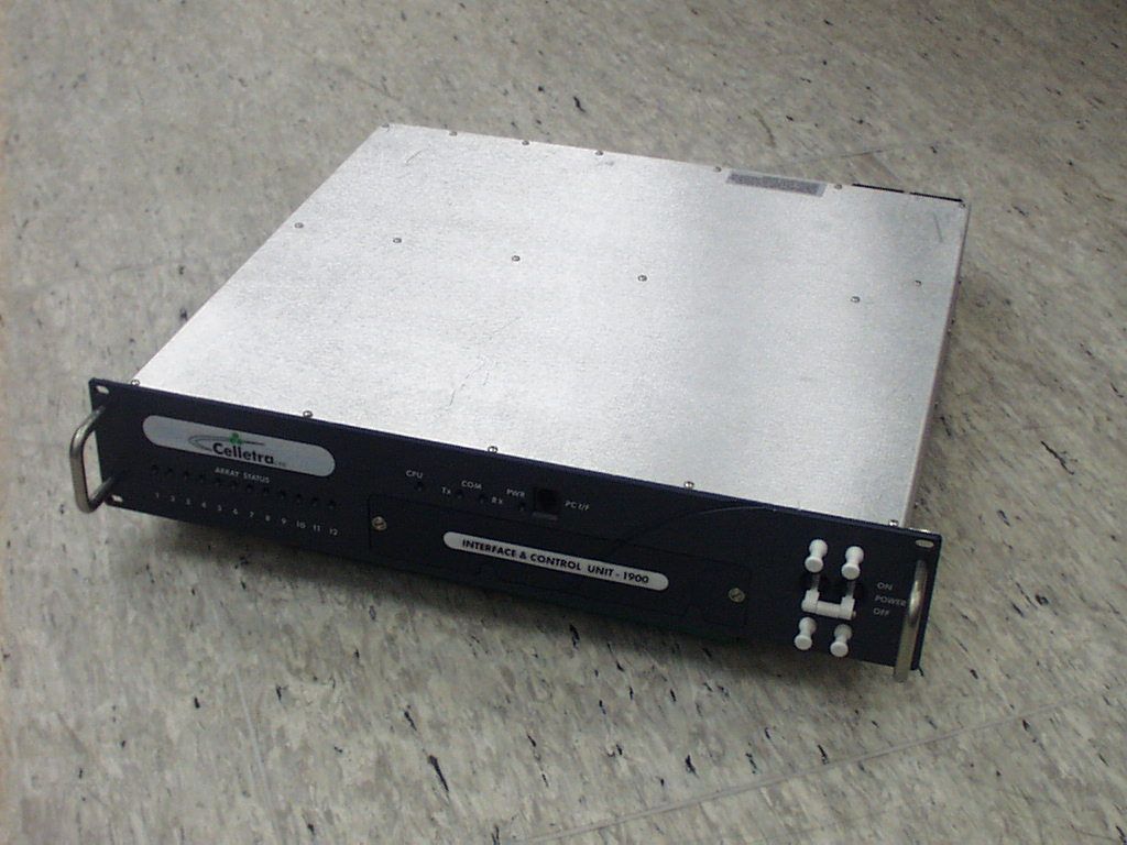
Cellular Transmission Solutions P.O. Box 106, Tavor building 1, Yoqne'am Ilit 20692, ISRAEL Tel. + 972 4 9592522 Fax. + 972 4 9592523 E-mail: [email protected] BEAMER ® Pol BEAMER ® PCS (3.2) Array System including Interface and Control Unit (ICU) Assembly & Operation Manual No.913000801 Name Date Signature Written By N. David Checked G. Argaman Approved M. Shalom Cellular Transmission Solutions P.O. Box 106, Tavor building 1, Yoqne'am Ilit 20692, ISRAEL Tel. + 972 4 9592522 Fax. + 972 4 9592523 E-mail: [email protected] Confidential, Proprietary Information Title: PolBEAMER PCS (3.2) Array System- Assembly and Operation Manual Doc. No.: 913000801 Rev.: 1 Page: 2 of 91 FCC Part 15A Compliance Statement This device complies with part 15 of the FCC rule. Operation is subject to the following two conditions: (1) this device may not cause harmful interference , and (2) this device must accept any interference received, including interference that may cause undesired operation Caution Changes or Modifications not expressly approved by Celletra Ltd. could void the user’s authority to operate the equipment” NOTE This equipment has been tested and found to comply with the limits for a Class A digital device, pursuant to part 15 of the FCC rules. These limits are designed to provide reasonable protection against harmful interference when the equipment is operated in a commercial environment. This equipment generates, uses, and can radiate Radio Frequency energy and, if not installed and used in accordance with the instructions manual, may cause harmful interference to radio communication. Operation of this equipment in a residential area is likely to cause harmful interference in which case the user will be required to correct the interference at his own expense. Cellular Transmission Solutions P.O. Box 106, Tavor building 1, Yoqne'am Ilit 20692, ISRAEL Tel. + 972 4 9592522 Fax. + 972 4 9592523 E-mail: [email protected] Confidential, Proprietary Information Title: PolBEAMER PCS (3.2) Array System- Assembly and Operation Manual Doc. No.: 913000801 Rev.: 1 Page: 3 of 91 PROPRIETARY NOTICE ALL DATA AND INFORMATION CONTAINED IN OR DISCLOSED BY THIS DOCUMENT IS CONFIDENTIAL AND PROPRIETARY INFORMATION OF CELLETRA LTD AND ALL RIGHTS THEREIN ARE EXPRESSLY RESERVE D. BY ACCEPTING THIS MATERIAL, THE RECIPIENT AGREES THAT THIS MATERIAL AND THE INFORMATION CONTAINED THEREIN IS HELD IN CONFIDENCE AND IN TRUST AND WILL NOT BE USE D, COPIED, REPRODUCED IN WHOLE OR IN PART. NOR ITS CONTENTS REVEALED IN ANY MANNER TO OTHER S, WITHOUT THE EXPLICIT WRITTEN PERMISSION OF CELLETRA LTD. Revision Description Date 0 Release May, 2001 1 Change Output Power to +40 dbm August 2001 Changes are periodically made to the information contained in this manual. These changes are published in the "software/hardware release notes", and will be incorporated into new editions. All rights are reserved. No parts of this manual may be reproduced in any form, without permission in writing from Celletra Ltd. Copyright © 1999, 2000 Celletra Ltd. BEAMER® is a trademark of Celletra Ltd. Celletra Ltd. reserves the right to change specifications without notice. CONTENTS Confidential, Proprietary Information Title: PolBEAMER PCS (3.2) Array System- Assembly and Operation Manual Doc. No.: 913000801 Rev.: 01 Page: 4 of 91 CONTENTS FIGURES TABLES 1. INTRODUCTION 10 1.1. Acronyms and Abbreviations 10 1.2. BEAMER® Array System Overview 11 1.2.1. BEAMER® Family Modular Concept.................................................................................... 13 1.3. Overview of the Interface and Control Unit (ICU) 13 1.3.1. Interface and Control Unit - ICU ............................................................................................. 13 1.3.2. ICU Controller Description ..................................................................................................... 14 1.3.3. RF Path Description................................................................................................................. 16 1.3.4. Bias-T Types............................................................................................................................ 16 1.4. Communication with BEAMER® and PC 17 1.4.1. Network Architecture and Capacity......................................................................................... 17 1.5. Communication Procedure 17 1.5.1. BEAMER® Monitoring and Control...................................................................................... 17 1.6. DC Distribution 18 1.7. Maintainability Requirements 19 2. INSTALLATION GUIDE 20 2.1. Applicable Documents 20 2.2. Scope 20 CONTENTS Confidential, Proprietary Information Title: PolBEAMER PCS (3.2) Array System- Assembly and Operation Manual Doc. No.: 913000801 Rev.: 01 Page: 5 of 91 2.3. Important Safety Precautions 21 2.3.1. Handling and Moving the BEAMER® Array ......................................................................... 21 2.3.2. System Measurement and Testing Conditions ......................................................................... 22 2.4. ICU Operation Instructions 23 2.4.1. DC Connections and Fuse Replacement .................................................................................. 23 2.4.2. Connecting the Unit to a Host PC or BTS Controller .............................................................. 24 2.4.3. Replacing the Back-Up Battery................................................................................................ 25 2.4.4. Bias-Ts 27 2.5. Array Installation 28 2.6. Assembly Instructions for the PCS 1x4x4 Array 28 2.6.1. Mounting Assembly (Figure 12): ............................................................................................. 28 2.6.2. BEAMER® Array Mounting (Figures 13 and 14): ................................................................ 29 2.6.3. BEAMER® Array Dismounting (Figures 13 and 14): ...........................................................…
Text truncated - open the document above for the full version.
Users Manual
Marianne Bosley From:Chris Harvey Sent:Tuesday, August 21, 2001 4:32 PM To:Marianne Bosley Cc:Liming Xu Subject:FW: #11086 Part 24 Certification for the 3.2 Array Here are the apparent changes. We will be issuing t he grant for 40dBm. Liming, does the report now reflect 40dBm? If not can you please remove the higher power references. Then this will be ready to Grant (I think). -----Origina l Message----- From:Jinae Szerensits Sent:Tuesday, August 21, 2001 9:10 AM To:Liming Xu Cc:Chris Harvey Subject:FW: #11086 Part 24 Certification for the 3.2 Array FYI- -----Origina l Message----- From:Gideon Argaman [SMTP:[email protected]] Sent:Tuesday, August 21, 2001 8:28 AM To:'Marianne Bosley' Cc:Jinae Szerensits; Israel Eldar; Yuval Shalgi Subject:RE: #11086 Part 24 Certification for the 3.2 Array Jinae Although MET has tested the Celletra PCS Rev.3.2 Array to meet requirements of the FCC Part 24 at Output Power levels of +45 dbm, we have made a decision to ask for Type approval for this equipment of +40 dbm only. We have made the necessary changes in the Installation and Operation Manual to reflect the output power level of +40 dbm on pages 45,48,49 of the manual , as has been asked by Mr. Liming of MET. We now expect to have the TCB Type approval for this piece of equipment shortly. Gideon Argaman Executive V.P and C.T.O Celletra Ltd. Tel: 972-4-9592522, Direct Tel: 972-9593951, Cell: 972-56-343488 Email: [email protected], WEB: www.celletra.com -----Original Message----- From: Marianne Bosley [mailto:[email protected]] Sent: Tuesday, 21 August, 2001 12:40 AM To: '[email protected]' Cc: Jinae Szerensits; '[email protected]'; '[email protected]'; '[email protected]'; Liming Xu Subject: #11086 Part 24 Certification for the 3.2 Array Hello Mr. Argaman, This is in response to your email dtd August 19 to Jinae Szerensits. We can issue the Grant in the lower power to agree with your manual, or the manual must be changed to agree with the higher power requested, and therefore, what the Grant would state. The FCC reviews all data submitted from the TCBs once the Grant of Equipment of Authorization is issued, and they are very particular that all test data and documentation backing that data be consistent. Therefore, we strive to ensure that there are no discrepancies, giving no reason for the FCC to question the Grant at a later time. Thank you and have a good day. Marianne T. Bosley EMC Administrator 410-354-3300, ext. 412
Cover Letter(s)
Cellular Transmission Solutions P.O.Box 106, Tavor building 1 Yoqne’am Ilit 20692, ISRAEL Tel. + 972 4 9592522 Fax. + 972 4 9592523 E-mail: [email protected] 1 July 22 nd , 2001 attn: Reviewing Engineer Federal Communications Commission 7435 Oakland Mills Road Columbia, MD 21046 Re: Type Acceptance – Celletra Ltd – Confidentiality Requested Model : PCS Rev.3 1x4x4 Column Array Product Code: C-BPB-BMT-NGVxxxx/1,2,3 FCC ID: PNQC-BPB Ladies and Gentlemen, Transmitted herewith on behalf of Celletra Ltd, is its request for confidentiality under FCC rule Section 0.459 of the Commission’s Rules, Celletra Ltd requests that certain specific technical information in the application be withheld from public inspection following grant of the application because the information contains confidential business information and/or trade secrets. These items, which are marked “CONFIDENTIAL” include: 1. Technical Description and Block Diagrams. (Exhibit 2) 2. Active circuit schematics and assembly drawings.(Exhibit 3) 3. Internal photographs of the unit. (Exhibit 6) Significant effort and resources in research, development, and product design innovation have been invested by Celletra Ltd and would be compromised if the materials for which confidentiality is requested were made available to competitors of Celletra Ltd as a result of this application. Celletra Ltd. has taken precaution measures to ensure that the customers or installers will not gain access to the Active modules internal parts. These include strict NDA agreements and Special Ceramic labels to detect any un-authorized module’s service. Accordingly, Celletra Ltd asks only that these specified items be held confidential after grant in order to maintain a fair and competitive marketplace.. If questions arise concerning this application, please contact Paul Lemson of Celletra Inc at 425-844-1210 or call me at +972-4-9593951 (e-mail: [email protected]) . Respectfully, Gideon Argaman CTO Celletra Ltd.
Test Report
FCC ID: PNQC-BPB August 28, 2001 Federal Communications Commission Authorization and Evaluation Division 7435 Oakland Mills Road Columbia, MD 21046 Attention:Applications Examiner Applicant:Cellular Transmission Solutions P.O. Box 106, Tavor building 1, Yoqne’am Ilit 20692, ISRAEL Equipment:BEAMER Active Radiating Module System (PCS Rev 3.21 x 4 Array) FCC ID: PNQC-BPB Specification:47 CFR, Part 24 Licensed Certification Dear Examiner: The following application for Grant of Equipment Authorization is presented on behalf of Cellular Transmission Solutions for the Licensed Certification of their BEAMER, PCS Repeater. Enclosed, please find a complete data and documentation package demonstrating that this device complies with the technical requirements of 47 CFR, Part 24, for a PCS Repeater. If you have any questions, please contact the undersigned, who is authorized to act as Agent. Sincerely, Chris Harvey Director, EMC Laboratory FCC ID: PNQC-BPB EMC11086- 2 -August 28, 2001 MET Laboratories, Inc. Safety Certification - EMI - Telecom Environmental Simulation 914 WEST PATAPSCO AVENUE !! BALTIMORE, MARYLAND 21230-3432 !! PHONE (410) 354-3300 !! FAX (410) 354-3313 ENGINEERING TEST REPORT in support of the Application for Grant of Equipment Authorization EQUIPMENT:BEAMER Active Radiating Module System FCC ID:PNQC-BPB Specification:47 CFR 24 On Behalf of the Applicant:Cellular Transmission Solutions P.O. Box 106, Tavor building 1, Yoqne’am Ilit 20692, ISRAEL Manufacturer:Cellular Transmission Solutions P.O. Box 106, Tavor building 1, Yoqne’am Ilit 20692, ISRAEL Manufacturer’s Mr. Israel Eldar Representative: Test Date(s):July 2 thru 10, 2001 ENGINEERING STATEMENT I ATTEST: the measurements shown in this report were made in accordance with the procedures indicated, and that the emissions from this equipment were found to be within the limits applicable. I assume full responsibility for the accuracy and completeness of these measurements. On the basis of the measurements made, the equipment tested is capable of operation in accordance with the requirements of Part 24 of the FCC Rules under normal use and maintenance. _____________________________ Liming Xu Project Engineer, MET Laboratories FCC ID: PNQC-BPB EMC11086- 3 -August 28, 2001 1.0INTRODUCTION The following data is presented on behalf of the Applicant, Cellular Transmission Solutions as verification of the compliance of the Beamer Array ( PCS Repeater), to the requirements of 47CFR 24. 2.0TEST SITE All testing was conducted at MET Laboratories, Inc., 914 West Patapsco Avenue, Baltimore, Maryland 21230-3493. Radiated emissions measurements were performed on a three-meter open area test site (OATS). A complete site description is on file with the FCC Laboratory Division as 31040/SIT/MET. 3.0TEST EQUIPMENT USED ManufacturerEquipment Calibration DueCal. Interval Hewlett Packard8563A Spectrum Analyzer6/14/01annual EMCOBiconical Antenna 31043/21/02annual EMCOEMCO Log Periodic Antenna11/01/01annual EMCODouble Ridge Guided Horn2/27/02annual Hewlett Packard8546A Analyzer8/23/01annual Rhode & Swartz (X3)SMIQ 03 Digital Signal Gen.8/16/01N/A 4.0EQUIPMENT UNDER TEST CONFIGURATION The EUT was configured with DC power supply modules and a digital signal generator was used to simulate a CDMA type RF input signals to the EUT. The EUT with host external computer was configured for maximum signal gain and bandwidth. The EUT was operated in a manner representative of the typical usage of the equipment. During all testing, the EUT was configured for Single Channel operation and Multi-Channel (3 Channel separated and Adjacented) which results in maximum possible output gain. 5.0TEST TYPE(S) 5.2Occupied Bandwidth: 47CFR2.1049, Input vs. Output 5.3RF Power Output: 47CFR 2.1046, 24.132(b),(c) 5.4Spurious Emission at Antenna Terminals: 47CFR 2.1051, 24.238(a) 5.5Intermodulatiom spur emissions FCC ID: PNQC-BPB EMC11086- 4 -August 28, 2001 Po&[43%10Log(10)]'&13dBm 6.0TEST RESULTS 6.1TEST TYPE: Radiated Emissions 6.1.1TECHNICAL SPECIFICATION:2.1053; 24.238(a) 6.1.2TEST DATE(S):July 8, 2001 6.1.3MEASUREMENT PROCEDURES: As required by 47 CFR 2.1053, field strength of spurious radiation measurements were made in accordance with the general procedures of ANSI C63.4-1992 "Methods of Measurement of Radio-Noise Emissions from Low-Voltage Electrical and Electronic Equipment in the Range of 9kHz to 40 GHz". Preliminary radiated emission measurements were performed inside a shielded chamber with all digital signal generators on and terminated. The frequency list from the preliminary measurements was used as a guide for making final measurements on a 10 meter open area test site. The unit was scanned over the frequency range of 9 kHz to 20 GHz. The Radiated Spurious Emissions Limit is obtained by the following: Based on an output power (as measured at the output of the RF Amplifier) of 10 watts: P o = 10 W the radiated power level of all spurious emissions must be attenuated by at least 43 + 10log(Po) below Po, yielding: All of the measurable radiated emissions are related to the digital device portion of the EUT, and thus are compared to the 47CFR 15 Class A field strength limit. Mathematical calculations indicate that these field strengths yield radiated power levels greater than 30 dB below the -13 dBm limit for spurious emissions from the transmitter portion of the EUT calculated above. There were no observable radiated emissions from the transmitter portion of the EUT. FCC ID: PNQC-BPB EMC11086- 5 -August 28, 2001 6.2TEST TYPE: Occupied Bandwidth 6.2.1TECHNICAL SPECIFICATION:47 CFR 2.1046 6.2.2TEST DATE(S):May 17, 2001 6.2.3MEASUREMENT PROCEDURES: As required by 47 CFR 2.1049, occupied bandwidth measurements were made on the PCS Repeater pre- and post- repeater. A digital signal generator was configured to transmit a CDMA carrier signal. Using an IF bandwidth of 100kHz, we determined the occupied bandwidth of the emission at the Input vs Output. 6.2.4RESULTS: Equipment co…
Text truncated - open the document above for the full version.
Test Report
Marianne Bosley From:Fr. Gregory Czumak [[email protected]] Sent:Friday, August 10, 2001 1:31 PM To:Marianne Bosley; [email protected] Subject:Re: FW: Celletra MET #11086 FCC ID:PNQC-BPB I have responded to Liming's answers, below, in bolf- faced type. The first 2 require a further response, while the 3rd one should be noted for future applications. Gregory Marianne Bosley wrote: Hi again, Here is Liming's response to your inquiries. Let me know what you think; he's here dayshift today, and we need to get this granted before Chris leaves. Thanks. Marianne T. Bosley EMC Administrator 410-354-3300, ext. 412 > -----Original Message----- > From: Liming Xu > Sent: Tuesday, August 07, 2001 3:27 PM > To: Marianne Bosley > Subject: RE: Celletra MET #11086 FCC ID:PNQC-BPB > > My answer inserted in each question. > > -----Original Message----- > From: Marianne Bosley > Sent: Tuesday, August 07, 2001 2:09 PM > To: Liming Xu > Cc: Marianne Bosley > Subject: FW: Celletra MET #11086 FCC ID:PNQC-BPB > > << File: #11086 checklist (PCS).doc >> > Liming, please review Greg's comments for this Celletra, and possibly > input for future and this one? > > -----Original Message----- > From: Greg Czumak > To: Marianne Bosley; Chris Harvey > Sent: 8/7/2001 2:04 PM > Subject: RE: Celletra MET #11086 FCC ID:PNQC-BPB > > > Tech review complete, RT questions below. Checklist attached. I seem > to remember doing another one from the same applicant some time back...I > think I had similar questions...this information should be clearly > placed in the application, as it is some of the main things that the FCC > looks for.... > > RT questions: > > 1. The RBW used to measure the output power (1 MHz) is less than the > emission bandwidth (EBW)(1.28 MHz). Please remeasure using an RBW > greater than the EBW and submit new data. > A. This question has been answered on last Celletral project. > again, on FCC TCB training RBW = or > 1MHz measure frequency above 1GHz. Every new application must stand on its own merit, previous applications cannot be just referenced. Any previous response to this, or a similar question, should be included in the present application as well. I am not sure to what FCC TCB training you are referring, but output power measurements should always be made with a RBW > or = the emission bandwidth, regardless of the frequency of the emission. I seem to recall that you submitted either new plots (last time) or a statement to the effect that increasing the RBW did not affect the reported levels. Please submit one of these 2 responses again. > > 2. There appear to be discrepancies wrt the output power: the > introduction to the test report (Section 6.1.3)states that the output > power is 8W, the graph on page 21 of the test report shows a conducted > output power level of 35W, and the technical description states that the > conducted output power is 10W, with an integral antenna gain of 13 dBi, > yielding an EIRP of 200W. Please clarify. Also, please note that > consistancy throughout the application (i.e., between technical > descriptions and measurement data) wrt output power is a primary concern > of the FCC's. > A. on page 21 output power level is 40dBm (10W). > total yielding an EIRP of 200W. The plot below the one to which you refer, on p.21, shows a power level of 45.33 dBm, or 34.12 W. Please clarify exactly which power is being requested to appear on the grant. If 10 W, please explain the referenced plot showing 34.12 W. Again, this is of primary concern to the FCC, and should be more clearly addressed in future application. > > > 3. Please verify that measurements were made on 3 different channels > (low, middle, and high frequencies), per Section 15.31(m). > A. This is an amplifier not a transmitter so no channel. Because filter characteristics of an amp may vary with frequency, in the future, please specify if the reported results are indicative of performance across the entire frequency band for which authorization is requested. > > > > > -----Original Message----- > From: Marianne Bosley > To: Greg Czumak > Sent: 8/3/2001 4:02 PM > Subject: Celletra MET #11086 FCC ID:PNQC-BPB > > Greg, This one was testing by Liming. Also this one has been promised > as quick as possible. > > <<emc11086.wpd>> <<Rev.3.2 Beamer Array System Assembly and Operation > Manual- 2.7_1.doc>> <<Beamer 3.2 Array type Acceptance Instructions > 28.6.01.doc>> <<Beamer Module.jpg>> <<ICU Picture.jpg>> <<PCS 3.2 1x4 > Array Pic.jpg>> <<Exhibit 7 PCS Filters plots 28.6.01.doc>> <<Multi > Channel measured performance for Beamer 1.7.01.doc>> > <<w2000PreCertificationTests Procedure 001108FRP1114c.pdf>> > <<FiBeamerHUBCertificate.doc>> <<FiBeamerRACCCertificate.doc>> > > If you need to view any of the photos, they are in the file folder > #11086. > > Marianne T. Bosley > EMC Administrator > 410-354-3300, ext. 412 > > <<#11086 checklist (PCS).doc>>
Contact Information
Applicant
Gideon Argaman(GVP & CIO)
Technical Contact
MET Laboratories, Inc.Liming Xu
[email protected]410-354-3300
914 West Patapsco Ave. · Baltimore, Maryland · United States
Non-Technical Contact
MET Laboratories, Inc.Marianne Bosley
[email protected]410-354-3300
Test Firm
MET Laboratories, Inc.John Mason
Technical Specifications
| # | Rule Parts | Frequency Range | Power Output | Emission |
|---|---|---|---|---|
| 1 | 24 | 1.93 GHz - 1.99 GHz | 10 W | F9W |
Other Applications from Celletra Ltd.

PNQ-C-ENCR-CBS021
Jun 14, 2004Cellular CellEnhancer Unit
Equipment Class
AMP - Amplifier
PNQC-MP1-M1
Dec 22, 2002PCS Beamer
Equipment Class
AMP - Amplifier
PNQC-EP2-NW
Nov 20, 2002Single Carrier CDMA PCS Apmlifier
Equipment Class
AMP - Amplifier
PNQC-UPB
Sep 08, 2002Single Channelized PCS Beamer Amplifier Unit
Equipment Class
AMP - Amplifier
PNQC-CPB
Sep 08, 2002Single Channelized PCS Coverage Enlightener Beamer
Equipment Class
AMP - Amplifier