POUMTK952N-0W2Dual Transmitter
Wisycom s.r.l.
Click to zoom
Application Details
- Equipment Class
- TNB - Licensed Non-Broadcast Station Transmitter
- Date of Grant
- Apr 11, 2015
- Application Purpose
- Original Equipment
- Date of Application
- Apr 11, 2015
- Equipment Note
- Dual Transmitter
- Frequency Range
- 614.10000000 - 697.90000000
- Company
- Wisycom s.r.l.
- Country
- Italy
Documents & Files
Document Text
Text extracted from the exhibit documents filed with the FCC. Open a document above to read the original.
Users Manual
MTK952 User Manual Dual Transmitter Mono - Stereo - Intercom Modulation SN: ________________ rev.06 (ref. FW 2.0) Date: 10 April 2015 MTK952 User Manual rev.06 1 BRIEF DESCRIPTION MTK952 is a versatile dual transmitter capable of working in a huge UHF bandwidth and of generating any kind of narrow-band modulations, with very high quality and low spurious emissions. Main features: 330 MHz Bandwidth (470 MHz – 800 MHz) 2400 user-defined frequencies (40 group by 60 freq.) Stereo, mono, intercom audio modulation Output power up to 2 Watt (/W option) Analogue & digital input (AES3) Redundant power supply 230/110 Vac & 12 VDC DSP audio processing (40bit floating point / 2Gflops) with multi-companding Direct Digital Synthesis (DDS) of signal for the highest flexibility and quality (> 70 dB stereo separation)s SWR (Stationary Wave Ratio) sensing on antenna outputs Above a schematic with the functional diagram of one transmitter of MTK952. MTK952 use extreme technologies like: Direct Digital Synthesizer (DDS) DDS is a type of frequency synthesizer used for creating arbitrary waveforms from a single, fixed-frequency reference clock. A DDS has many advantages over its analog counterpart, the phase-locked loop (PLL), including much better frequency agility, improved phase noise, and precise control of the output phase across frequency switching transitions. The Direct Digital Synthesis (DDS) technology can generate virtually any kind of modulation while keeping an absolute phase accuracy. Double conversion stage Using a double conversion and saw filter at IFs (intermediate frequencies) we can achieve a very low spurious emission and a great bandwidth agility (330 MHz). Intermodulation cancelling power amplifiers PA module (power amplifiers) is designed with an exclusive circuitry that reduce the intermodulation generated by external carriers using a wideband phase cancelling design. Digital audio with Shark™ DSP 40bit floating point & 2 Gflops power from Analog Device A very powerful Analog Design Shark DSP processor manages the audio with very low delay (< 1 ms) and emulates by software all companding and pre-emphasis effects. MTK952 User Manual rev.06 2 SAFETY INSTRUCTION Read this safety instruction and the manual first Follow all instructions and information. Do not lose this manual. Do not use this apparatus under the rain or near the water. Do not install the apparatus near heaters or in hot environments, do not use outside the operating temperature range. Mount the apparatus as indicated in the instruction, do not block side grids for air ventilation ATTENTION: supply the apparatus with a correct mains voltage and with the ground connection. Check the power cord integrity. The power cord must be protected from damage Do not install the apparatus near heaters or in hot environments, do not use outside the operating temperature range. Do not open the apparatus, only qualified service technician are enabled to operate on it. The apparatus needs servicing when it is not properly working or is damaged by liquids, moisture or other objects are fallen in the apparatus. Use only accessories or replacement parts authorized or specified by the manufacturer. Clean the apparatus only with dry cloths, do not use liquids. The ON/OFF is a double pole circuit breaker, but to ensure the complete disconnection of the apparatus, disconnect the power cord. Report the serial number and the purchasing date in front of the manual. It is needed to have proper replacement parts or accessories from the manufacturer. When replacement parts are needed, use only replacement parts authorized from the manufacturer. Substitution with not authorized parts could result in electric shock, hazards or fire. Keep attention on all the labels with warnings or hazards on the apparatus. WARNING! The apparatus is intended for professional use; anyway the manufacturer alerts the user that the headphone output power of the apparatus could exceed the level of 85 dB(A) of sound pressure level and this could be dangerous for the hearings. Do not use the headphone with high power level or for long time. Reduce the power or suspend the hearing in case of any kind of hearing problem. MTK952 User Manual rev.06 3 QUICK START INSTRUCTION 1. Connect to the power outlet using the supplied power cable (see rear panel: connector 1) 2. Attach the antennas to the antenna out BNC connections (N connectors for MTK952N) (see rear panel: connectors 8 and 13) 3. Connect the audio sources to the relative audio input connectors (see rear rear panel: connectors 7 for digital audio sources, connectors 9÷12 for analog audio sources) NOTE: the cascade configuration allows to use the same analog audio input for more transmitter 4. Power on the MTK952 5. Switch off the RF output: a. While the MTK952 is powering on and the progress bar appears, push the 3 rd button at the bottom (see indication “OFF” on the display) b. At the end of MTK952 power on, push the lower button on the right of the displays 6. Enter in the MAIN>Audio source menu and a. configure the input parameter between digital and analog (according to the audio source connected at point 3) b. configure the AF level meter parameter as modulation c. if digital audio source: leave audio gain left and right parameters to 0dB and adjust the audio level with the mixer if need change the audio gain left and right parameters d. if analog audio source: leave audio gain left and right parameters to 0dB and adjust Max audio level parameter. NOTE: this parameters is unique for both the channels (right and left) if need change the audio gain left and right parameters NOTE: adjust the audio level (thru the mixer and/or Max audio level and/or the audio gain left and right parameters) so that, for the maximum input signal level, the AF level bars show the MAXIMUM NUMBERS OF GREEN LED INDICATORS AND NO YELLOW/RED CLIP LED INDICATORS the MOD. (modulation) b…
Text truncated - open the document above for the full version.
External Photos
Test report no.: 1-9103/14-01-01_AnnexA Page 1 of 6 Annex A This test report annex is electronically signed and valid without handwriting signature. For verification of the electronic signatures, the public keys can be requested at the testing laboratory. Test report annex authorised: David Lang Radio Communications & EMC Test report no.: 1-9103/14-01-01_AnnexA Page 2 of 6 External ph ot os o f t he EU T Photo 1: Photo 2: Test report no.: 1-9103/14-01-01_AnnexA Page 3 of 6 Photo 3: Photo 4: Test report no.: 1-9103/14-01-01_AnnexA Page 4 of 6 Photo 5: Photo 6: Test report no.: 1-9103/14-01-01_AnnexA Page 5 of 6 Photo 7: Photo 8: Test report no.: 1-9103/14-01-01_AnnexA Page 6 of 6 Docu men t his to r y Version Applied changes Date of release Initial release 2015-03-10
ID Label/Location Info
Models: MTK952N-0W2-US FCC-ID: POUMTK952N-0W2 IC: 11967A-MTK952N0W2, Variants: MTK952N-0W2, MTK952N-0W2-US_DC, MTK952N-0W2-US_MS, MTK952N-0W2-US_MS-DC Models: MTK952N-2W0-US FCC-ID: POUMTK952N-2W0 IC: 11967A-MTK952N2W0 Variants: MTK952N-2W0-US, MTK952N-2W0-US_DC, MTK952N-2W0-US_MS, MTK952N-2W0-US_MS-DC Label & Position Model: MTK952N-0W2-US Model: MTK952N-2W0-US
Internal Photos
Test report no.: 1-9103/14-01-01_AnnexB Page 1 of 7 Annex B This test report annex is electronically signed and valid without handwriting signature. For verification of the electronic signatures, the public keys can be requested at the testing laboratory. Test report annex authorised: David Lang Radio Communications & EMC Test report no.: 1-9103/14-01-01_AnnexB Page 2 of 7 Inter nal p ho tos of the E UT Photo 1: Photo 2: Test report no.: 1-9103/14-01-01_AnnexB Page 3 of 7 Photo 3: Photo 4: Test report no.: 1-9103/14-01-01_AnnexB Page 4 of 7 Photo 5: Photo 6: Test report no.: 1-9103/14-01-01_AnnexB Page 5 of 7 Photo 7: Photo 8: Test report no.: 1-9103/14-01-01_AnnexB Page 6 of 7 Photo 9: Photo 10: Test report no.: 1-9103/14-01-01_AnnexB Page 7 of 7 Docu men t his to r y Version Applied changes Date of release Initial release 2015-04-10
RF Exposure Info
2015-04-11 Page 1 of 3 Radio Frequency Exposure Evaluation §1.1310 Requirements Project.: 1-5824/13-14 2015-04-11 Page 2 of 3 General Limits: Also the maximum admissible allowed antenna gain for shown application is calculated not exceeding the MPE limit. Project.: 1-5824/13-14 2015-04-11 Page 3 of 3 Max antenna gain calculations Based on valid limits on ERP/EIRP and max. MPE the maximum antenna gain which can be used for the specific application is calculated. Band 1 (470 MHz –608MHz) P = 23.0dBm (0.2 Watt) S = 0.31 mW/cm 3 (470 MHz/ 1500) Max. antenna gain: 9.0 dBi Band 2 (614 MHz –698MHz) P = 23.0dBm (0.23 Watt) S = 0.41 mW/cm 3 (614 MHz/ 1500) Max. antenna gain: 10.1 dBi The maximum antenna gain to be used with the device shall not exceed 9.0 dBi. David Lang Radio Communications & EMC
Test Report
TEST REPORT Test report no.: 1-9103/14-01-02-A Testing laboratory Applicant CETECOM ICT Services GmbH Untertuerkheimer Strasse 6 – 10 66117 Saarbruecken / Germany Phone: + 49 681 5 98 - 0 Fax: + 49 681 5 98 - 9075 Internet: http://www.cetecom.com e-mail: [email protected] Accredited Testing Laboratory: The testing laboratory (area of testing) is accredited according to DIN EN ISO/IEC 17025 (2005) by the Deutsche Akkreditierungsstelle GmbH (DAkkS) The accreditation is valid for the scope of testing procedures as stated in the accreditation certificate with the registration number: D-PL-12076-01-00 Wisycom SRL Via Spin, 156 36060 Romano D°Ezzelino - Vicenza / ITALY Phone: +39 04 24 38 26 05 Fax: +39 04 24 38 27 33 Contact: Nadia Sbrissa e-mail: [email protected] Phone: +39 04 24 38 26 05 Manufacturer Wisycom SRL Via Spin, 156 36060 Romano D°Ezzelino - Vicenza / ITALY Test standard/s 47 CFR Part 74 Title 47 of the Code of Federal Regulations; Chapter I Part 74 - Experimental radio, auxiliary. special broadcast and other program distribution services RSS – 210 Issue 8 Amendment 1 Licence-Exempt, Low-Power Radio Apparatus Operating in the Television Bands For further applied test standards please refer to section 3 of this test report. Test Item Kind of test item: Dual Transmitter Model name: MTK952N-0W2-US FCC ID: POUMTK952N-0W2 IC: 11967A-MTK952N0W2 Frequency: 470 MHz to 608 MHz and 614 MHz to 698 MHz Technology tested: Proprietary Antenna: External antenna Power supply: 120 V AC Temperature range: -10°C to +55°C This test report is electronically signed and valid without handwriting signature. For verification of the electronic signatures, the public keys can be requested at the testing laboratory. Test report authorised: Test performed: Stefan Bös David Lang Radio Communications & EMC Radio Communications & EMC Test report no.: 1-9103/14-01-02-A Page 2 of 45 1 Table of contents 1 Table of contents ............................................................................................................................................ 2 2 General information ....................................................................................................................................... 3 2.1 Notes and disclaimer .......................................................................................................................... 3 2.2 Application details ............................................................................................................................... 3 3 Test standard/s ............................................................................................................................................... 3 4 Test environment ............................................................................................................................................ 4 5 Test item .......................................................................................................................................................... 4 5.1 Additional information ........................................................................................................................ 4 6 Test laboratories sub-contracted ................................................................................................................. 4 7 Description of the test setup ......................................................................................................................... 5 7.1 Radiated measurements ..................................................................................................................... 5 7.1 Conducted measurements ................................................................................................................. 6 8 Summary of measurement results ............................................................................................................... 7 8.1 Additional comments .......................................................................................................................... 8 9 Measurement results ...................................................................................................................................... 9 9.1 Output power (conducted) .................................................................................................................. 9 9.2 Frequency stability ............................................................................................................................ 10 9.2.1 Frequency error vs. temperature ..................................................................................................... 10 9.2.2 Frequency error vs. voltage ............................................................................................................. 14 9.3 Modulation characteristics ............................................................................................................... 16 9.4 Occupied bandwidth ......................................................................................................................... 18 9.5 Unwanted radiation (spectrum mask) ............................................................................................. 26 9.6 Field strength of spurious radiation (radiated) .............................................................................. 33 9.7 Field strength of spurious radiation (conducted) .......................................................................... 35 10 Test equipment and ancillaries used for tests ...................................................................................... 43 11 Observations ............................................................................................................................................. 43 Annex A Document history .......................................................................................................................... 44 Annex B Further information .....…
Text truncated - open the document above for the full version.
Test Setup Photos
Test report no.: 1-9103/14-01-01_AnnexC Page 1 of 6 Annex C This test report annex is electronically signed and valid without handwriting signature. For verification of the electronic signatures, the public keys can be requested at the testing laboratory. Test report annex authorised: David Lang Radio Communications & EMC Test report no.: 1-9103/14-01-01_AnnexC Page 2 of 6 EUT Test se tu p p h otos Photo 1: Photo 2: Test report no.: 1-9103/14-01-01_AnnexC Page 3 of 6 Photo 3: Photo 4 (with combiner): Test report no.: 1-9103/14-01-01_AnnexC Page 4 of 6 Photo 5 (with combiner): Photo 6 (with combiner): Test report no.: 1-9103/14-01-01_AnnexC Page 5 of 6 Photo 7 (with combiner): Test report no.: 1-9103/14-01-01_AnnexC Page 6 of 6 Docu men t his to r y Version Applied changes Date of release Initial release 2015-03-11
Contact Information
Applicant
Enzo Frigo(CTO)
Test Firm
cetecom advanced GmbHGerald Schmidt
Technical Specifications
| # | Rule Parts | Frequency Range | Power Output | Emission | Tolerance |
|---|---|---|---|---|---|
| 4 | 74 | 614.1 MHz - 697.9 MHz | 200.00 mW | 200KF8E | 1 ppm |
Other Applications from Wisycom s.r.l.
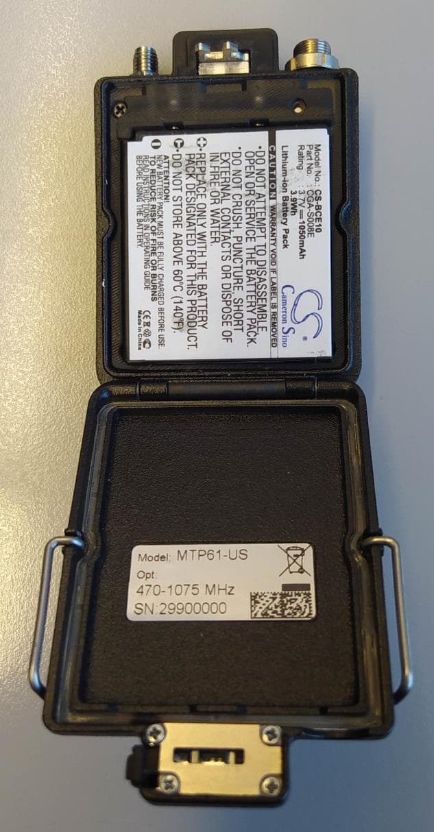
POUMTP61
Jul 23, 2023Wireless Microphone
Equipment Class
DWM - Part 15 Wireless Microphone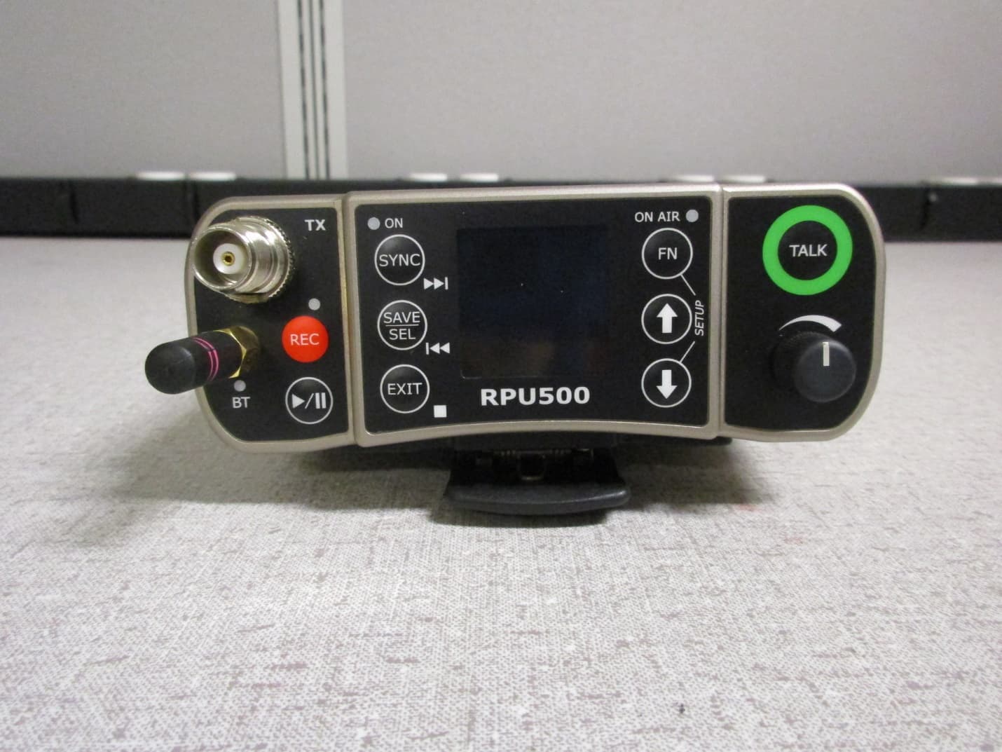
POURPU500
Sep 08, 2021Wireless Microphone
Equipment Class
DWM - Part 15 Wireless Microphone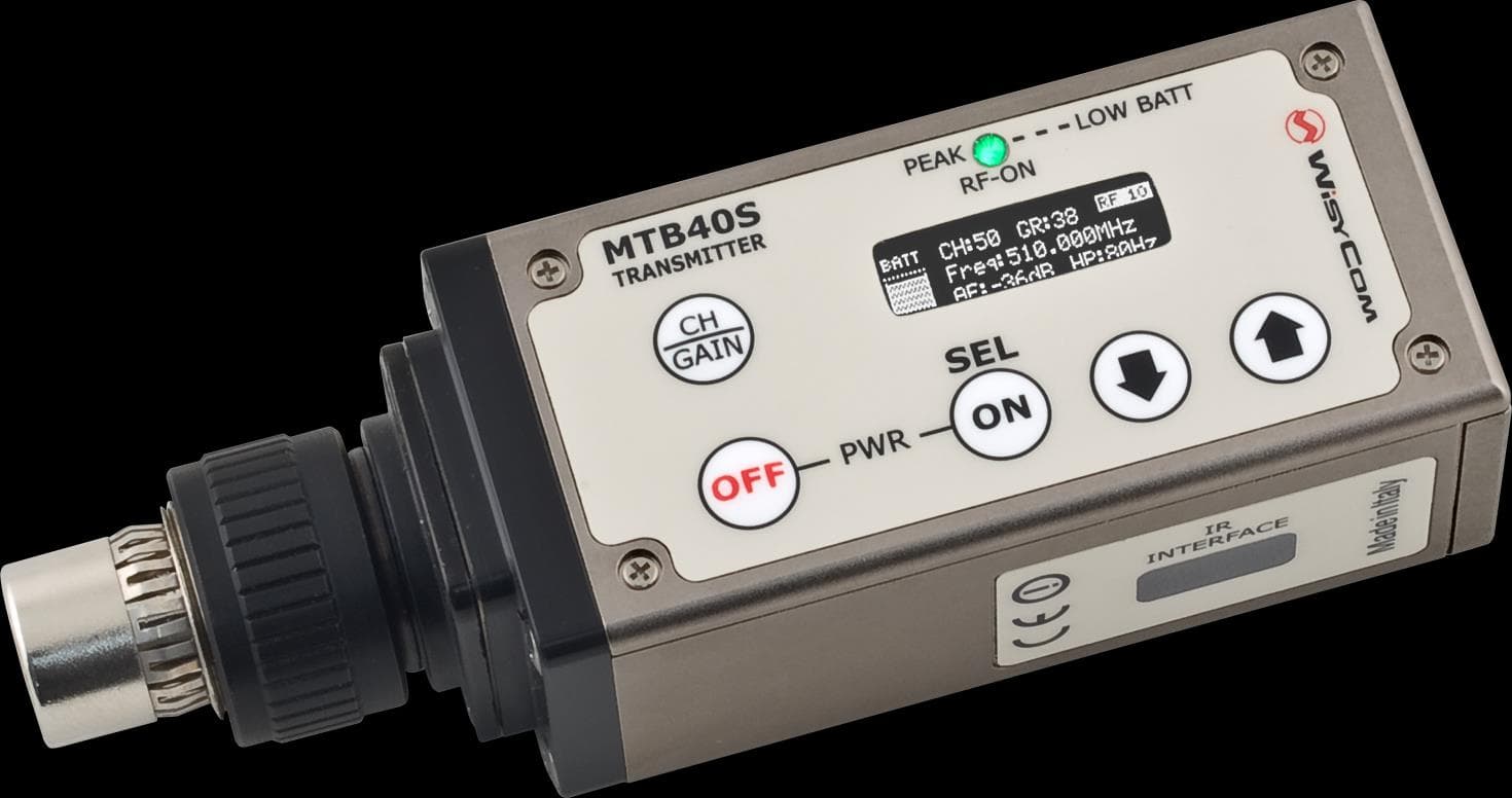
POUMTB40SUSX
Apr 20, 2015Plug on transmitter
Equipment Class
TBC - Licensed Broadcast Station Transmitter
POUMTK952N-2W0
Apr 10, 2015Dual Transmitter
Equipment Class
TNB - Licensed Non-Broadcast Station Transmitter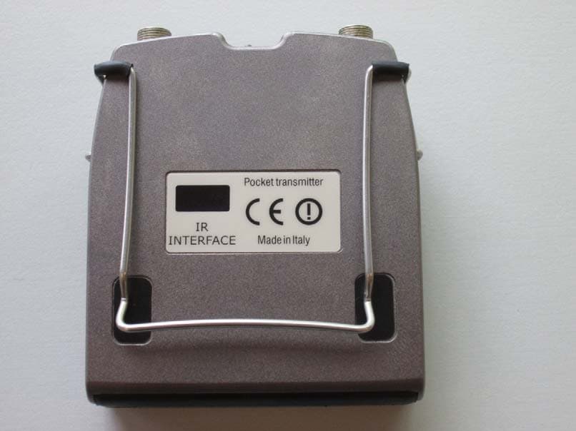
POUMTP40SUSX
Jul 01, 2014Wideband bodypack transmitter
Equipment Class
TBT - Licensed Broadcast Transmitter Worn on Body