POUMTP40SUSXWideband bodypack transmitter
Wisycom s.r.l.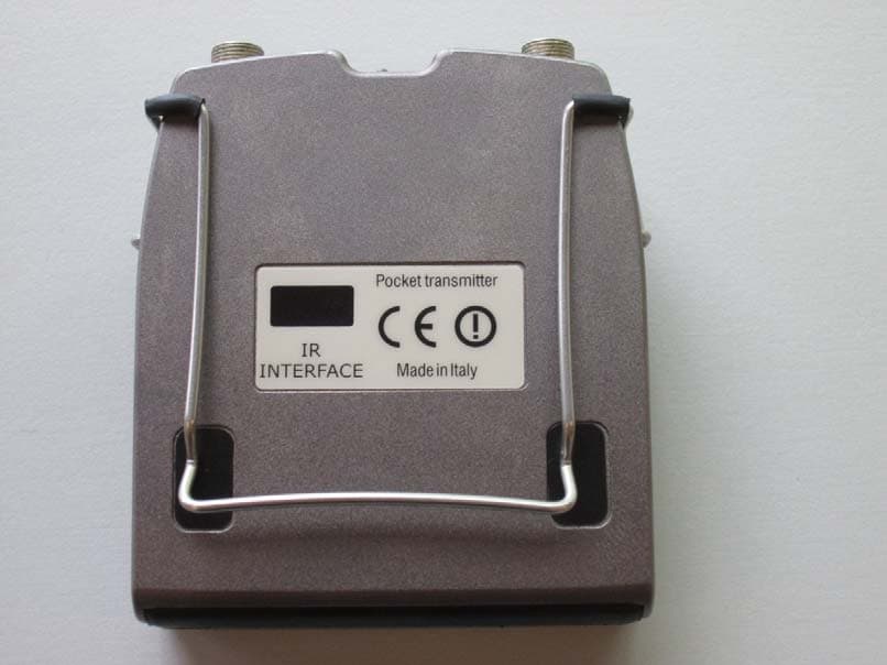
Click to zoom
Application Details
- Equipment Class
- TBT - Licensed Broadcast Transmitter Worn on Body
- Date of Grant
- Jul 01, 2014
- Application Purpose
- Original Equipment
- Date of Application
- Jun 29, 2014
- Equipment Note
- Wideband bodypack transmitter
- Frequency Range
- 614.07500000 - 697.92500000
- Company
- Wisycom s.r.l.
- Country
- Italy
Documents & Files
Document Text
Text extracted from the exhibit documents filed with the FCC. Open a document above to read the original.
Users Manual
MTP40S-US/USX User Manual Wideband Wireless Professional Pocket Transmitter SN: ________________ Rev.02 (ref. FW 1.22.0D) Date: 08 May 2014 MTP40 E-series MTP40S-US/USX User Manual Rev.02 2 MTP40S-US/USX User Manual Rev.02 3 INTRODUCTION “MTP40S is an extremely small and light pocket transmitter especially designed for professional wireless microphone applications” Very easy and quick to use thanks to OLED display, dedicated buttons and a joggle selector. MTP40S benefits also of the latest Wisycom RF technology along with an enhanced robustness against noise and inter-modulation. Fig. 1 ❶ Switch to enable wireless transmission, it also indicates the battery status and peak/mute operation (with PTT) ❷ In order to allow front visibility same colour information on (1) is replicated with this LED ❸ Oled display for transmitter setup ❹ <ch>, <gain> and 3 positions <selector> ❺ Battery holder ❻ Cover (to open push side buttons) 1. 6 5 4 3 2 Turn on wireless: Move the Wireless power switch in “I” position. 1 Open MIC Body: Push the side buttons and flip down the cover, to access internal setup controls and batteries. Turn on display: Push <select switch> and hold it. Front LED RGB. Fig. 2 MTP40S-US/USX User Manual Rev.02 4 SAFETY INSTRUCTION Read this safety instruction and the manual first Follow all instructions and information. Do not lose this manual. Do not use this apparatus under the rain or near the water. Do not install the apparatus near heaters or in hot environments, do not use outside the operating temperature range. Do not open the apparatus, only qualified service technician are enabled to operate on it. The apparatus needs servicing when it is not properly working or is damaged by liquids, moisture or other objects are fallen in the apparatus. Use only accessories or replacement parts authorized or specified by the manufacturer. Clean the apparatus only with dry cloths, do not use liquids. Report the serial number and the purchasing date in front of the manual. It is needed to have proper replacement parts or accessories from the manufacturer. When replacement parts are needed, use only replacement parts authorized from the manufacturer. Substitution with not authorized parts could result in electric shock, hazards or fire. Keep attention on all the labels with warnings or hazards on the apparatus. LED INDICATIONS Led indication with LED RGB (red, green, blue) in front led (2): - Wireless transmission status: Green when RF transmission power is on, Red when RF transmission power is off. Blue when the input signal is above the peak threshold - Battery status: green steady, slowly blinking (< 25%), quickly blinking (<12%). - Modulation peek (if activated and the limiter is disabled): red. - Ptt status: red if active (push to talk “pushed”). BATTERIES MTP40S is working with 2 AA alkaline or NiMH batteries (select correct type on setup controls). Battery status can be checked on internal OLED display or looking to LED status on power switch (see 1.1). BATTERY SUBSTITUTION Open transmitter cover and insert batteries following polarity indicated. Attention: always replace both the batteries MTP40S-US/USX User Manual Rev.02 5 POWERING UP Move the wireless power switch (see Fig. 1) in “I” position to activate wireless transmission: a green LED lights up (blinking when battery is low!) SETUP CONTROL Open transmitter Body to access the “display and controls” area (Fig. 3): A. Graphics Display (OLED) B. Channel selection buttons (ch) C. MIC gain setup buttons (gain) D. 3 position selector (up / down / click) Fig. 3 OLED POWER UP (OLED IS IN OFF CONDITION) Pushing down selector (click), oled turns on. A first menu with serial NO and brand logo is displayed, then <status> menu enters automatically. Pushing and holding selector, serial NO menu is displayed. OLED POWER DOWN (OLED IS IN ON CONDITION) Display turns off automatically after 15 sec, unless in <IRDA> menu or in <AUDIO> menu (with audio level < 5% from nominal). + - CLICK A B C D MTP40S-US/USX User Manual Rev.02 6 DISPLAY MENU Setup menu are accessed in sequence: MENU STATUS PRESET Current Load FACTORY/USER/PRESET1/2/3/4/5/6/7/8 Save USER TUNING CH 00-59 GR 00-39 Freq 1: 470.000÷640.000 2: 566.000÷798.000 3: 510.000÷698.000 AUDIO AF In Gain -60÷40 dsB (1dB step) Phase 0/180 HPass Filter Flat/60/80/120/170/250/400Hz Noise R. ENR-Wisy/ENC-Wisy Limiter On/Off MIC Mode 2 wires/2wires+bias/3 wires/ 2wire&pha/2w+bias&pha PTT Disable/Normal/Muting/No Data RF/Battery RF Power 10/50/100 mW Battery Alkaline/NiMH LED Led Light 0÷16 Led Mode None/ModPeak/PTT IRDA Lock Preset parameters MTP40S-US/USX User Manual Rev.02 7 + - CLICK Using <+/-> selector all menus can be accessed in sequence, push <click> to enter edit mode (in the left side of the display appear the word EDIT and the parameter start blinking): <+/-> to setup field <click> again to confirm changes and exit. exit without confirmation if no button is pressed after a few seconds time out. <START UP> menu These menus are displayed during power up for few seconds. First one gives information of antenna to be used. The number displayed is the center-band of the antenna to be used. The second menu gives indication on product: product id (MTP40S), a letter which identify the working band 1 470-640 2 566-798 3 510-698 a number which identify the hardware version, the firmware release (120.0B), the band in extended format and the serial number. Keep selector pushed to hold this menu! <STATUS> menu This is the first menu displayed after power up. Major info are displayed: - Current channel/group (i.e. CH:00 GR:39) - Current frequency (i.e. 566.000 MHz) - Mic gain (i.e. AF: +00 dB) and high pass filter (i.e. HP:60 Hz) - “RF 100” or RF 50” or “RF 10” on top right if RF transmission is on at 100mW or 50mW or 10mW of power respectively - On bottom battery bar is displayed <PRESET> menu This menu can be entered by scrolling selector, or pushing at the same time both quick ch…
Text truncated - open the document above for the full version.
Cover Letter(s)
CONFIDENTIALITY REQUEST Federal Communication Commission Equipment Authorization Division, Application Processing Branch 7435 Oakland Mills Road Columbia, MD 21048 April 11, 2014 TO WHOM IT MAY CONCERN Pursuant to Paragraphs §0.457 and 0.459 of the Commission’s Rules (47 C.F.R.) and Section §552(b)(4) of the Freedom of Information Act, Company requests confidentiality for the following products: FCC ID Number Product Title/Model: POUMTP40SUSX MTP40S-USX For the product stated above, we request that the following information be held confidential: 1. Circuit diagrams submitted as Equipment Authorization Electronic Filing attachment: "schematics”. 2. Block diagram submitted as Equipment Authorization Electronic Filing attachment: “block diagram”. 3. Operational description submitted as Equipment Authorization Electronic Filing attachment: “operational description” 4. Part list submitted as Equipment Authorization Electronic Filing attachment: “Part List” 5. Tuning procedure submitted as Equipment Authorization Electronic Filing attachment: “Tuning Procedure” The above exhibits contain Company trade secrets and proprietary information that could be of benefit to our competitors regarding the design of our mobile handset. This material is not customarily available to the general public and we request that it be withheld from public inspection. If you have any questions, please feel free to contact me at the address shown below. Sincerely, Name: Franco Maestrelli Company: Wisycom srl uninominale Address: via Spin, 156 36060 Romano d’Ezzelino-VI (Italy) Phone: +39 0424382605 Email: [email protected]
Cover Letter(s)
WISYCOM s.r.l. Via Spin, 156 I-36060 Romano d’Ezzelino (VI) Italy Tel. +39 0424 382605 Fax +39 0424 382733 www.wisycom.com e-mail: [email protected] FCC-ID: POUMTP40SUSX FCC IDENTIFIER Wisycom S.R.L. grants the following rules: - the FCC identifier is placed in the battery compartment and the batteries installed don’t compromise the visibility of the FCC label - the user doesn’t required any special tools for access to the battery compartment - the FCC label isn’t placed on a removable part - the user manual reports clear information where find the FCC label WISYCOM S.R.L. Unipersonale Amministratore Unico Franco Maestrelli
External Photos
FCC-ID: POUMTP40SUSX Page 1 of 2 Issue Date: 2014-05-15 External photos of WISYCOM SRL MTP40S-USX Excerpt of test report # EMCC-110265F, 2014-04-14 © EMCCons DR. RAŠEK GmbH & Co. KG 2014 Exemplary photo of EUT #T1541593, front view Exemplary photo of EUT #T1541593, top view FCC-ID: POUMTP40SUSX Page 2 of 2 Issue Date: 2014-05-15 External photos of WISYCOM SRL MTP40S-USX Excerpt of test report # EMCC-110265F, 2014-04-14 © EMCCons DR. RAŠEK GmbH & Co. KG 2014 Exemplary photo of EUT #T1541593, bottom view Exemplary photo of EUT #T1541593, battery case view
Internal Photos
FCC-ID: POUMTP40SUSX Page 1 of 2 Issue Date: 2014-05-15 Internal photos of WISYCOM SRL MTP40S-USX Excerpt of test report # EMCC-110265F, 2014-04-14 © EMCCons DR. RAŠEK GmbH & Co. KG 2014 Main board of EUT #T1541593, top Main board of EUT #T1541593, bottom FCC-ID: POUMTP40SUSX Page 2 of 2 Issue Date: 2014-05-15 Internal photos of WISYCOM SRL MTP40S-USX Excerpt of test report # EMCC-110265F, 2014-04-14 © EMCCons DR. RAŠEK GmbH & Co. KG 2014 Main board of EUT #T1541595, top Main board of EUT #T1541595, bottom
Test Report
lp-or^çç'. Page 1 of70 TEST REPORT # EMGC-110265F 2014-04-14 EQUIPMENT UNDER TEST Trade Name: MTP4OS Pocket Transmitter Model: MTP40S-USX Serial No: T1541593, T1541595 Equipment Category: Wideband bodypack transmitter Manufacturer: WISYCOM SRL Via Spin, 156 36060 Romano d'Ezzelino (Vl) Italy Applicant: same as manufacturer Phone: +39 0424 382605 E-Mail: [email protected] RELEVANT STANDARD(S): FCC Rules & Regulations, Title 47 - Part74.861 lC RSS-123 Section 5 MEASUREMENT PROCEDURE USED: ANSI/TIA.6O3-D TEST REPORT PREPARED BY: Patrick Reusch EMCCons DR. RASEK GmbH & Co. Moggast, Boelwiese I 91320 Ebermannstadt Germany Phone: +49 9194 9016 Fax: +49 9194 8125 E-mail: p. [email protected] KG TEST PERSONEL: Patrick Reusch HEAD OF GROUP: t? iÄ Þ. Wolfoano Dörino EMCCons OR. RRSCT GmbH & Co. KG Moggast, Boelw¡ese I 91320 Ebermannstadt Germany I 10265F EMC, Radio, Safety and Env¡ronmental Tssting D, lf DAkks rl Deutsche Akkreditierungsstelle D-PL-12067-01-00 Telephone: +49 9194 9016 Telefax: +49 9194 8125 Mail: [email protected] Web: http://www.emcc.de FCC-ID: POUMTP40SUSX Test Report # EMCC-110265F Page 2 of 70 Issue Date: 2014-04-14 FCC and IC Radio Tests on WISYCOM SRL MTP40S-USX CONTENTS Page 1 GENERAL INFORMATION................................................................................................................ 4 1.1 Limits and Reservations ......................................................................................................... 4 1.2 Test Location .......................................................................................................................... 4 1.3 Manufacturer .......................................................................................................................... 5 1.4 Applicant ................................................................................................................................. 5 1.5 Dates ...................................................................................................................................... 5 1.6 Ordering Information ............................................................................................................... 5 1.7 Climatic Conditions ................................................................................................................. 5 2 PRODUCT DESCRIPTION ................................................................................................................ 6 2.1 Equipment Under Test (EUT) ................................................................................................. 6 2.2 EUT Peripherals ..................................................................................................................... 6 2.3 Mode of Operation during Testing........................................................................................... 6 2.4 Modifications required for Compliance .................................................................................... 6 3 TEST RESULTS SUMMARY ............................................................................................................. 7 4 RF OUTPUT POWER ........................................................................................................................ 8 4.1 Regulation .............................................................................................................................. 8 4.2 Test Equipment ...................................................................................................................... 8 4.3 Test Procedures ..................................................................................................................... 9 4.4 Results ................................................................................................................................... 9 5 AUDIO MODULATION CHARACTERISTICS .................................................................................. 10 5.1 Regulation ............................................................................................................................ 10 5.2 Test Equipment .................................................................................................................... 10 5.3 Test Procedures ................................................................................................................... 10 5.4 Results ................................................................................................................................. 11 6 FREQUENCY STABILITY ............................................................................................................... 12 6.1 Regulation ............................................................................................................................ 12 6.2 Test Equipment .................................................................................................................... 12 6.3 Test Procedures ................................................................................................................... 13 6.4 Results ................................................................................................................................. 13 7 EMISSION BANDWIDTH ................................................................................................................. 14 7.1 Regulation ............................................................................................................................ 14 7.2 Test Equipment .................................................................................................................... 14 7.3 Test Procedures ................................................................................................................... 15 7.4 Results ................................................................................................................................. 15 8 SPURIOUS EMISSIONS AT ANTENNA PORT .....................…
Text truncated - open the document above for the full version.
Test Report
FCC-ID: POUMTP40SUSX Test Report # EMCC-110265F Page 51 of 70 Issue Date: 2014-04-14 FCC and IC Radio Tests on WISYCOM SRL MTP40S-USX Prescan, 1 – 7 GHz EUT: # T1541593 Frequency: 470 MHz Orientation of the EUT: lying & standing Final measurement result: No peaks above noise floor. * * A 3DB RBW 1 MHz VBW 3 MHz TDF PA A tt 0 dB**Ref 77 dBμV/m Start1 GHzSto p 7 GHz600 MHz/ 1 PK MAXH SWT 1 s* SGL 25 30 35 40 45 50 55 60 65 70 7 5 80 D1 82.3 dB* D2 70.3 dB* POS 77 dB* Date: 2.MAY.2014 15:00:49 © EMCCons DR. RAŠEK GmbH & Co. KG 2014 110265F FCC-ID: POUMTP40SUSX Test Report # EMCC-110265F Page 52 of 70 Issue Date: 2014-04-14 FCC and IC Radio Tests on WISYCOM SRL MTP40S-USX Prescan, 30 – 1000 MHz EUT: # T1541593 Frequency: 607.925 MHz Orientation of the EUT: lying © EMCCons DR. RAŠEK GmbH & Co. KG 2014 110265F FCC-ID: POUMTP40SUSX Test Report # EMCC-110265F Page 53 of 70 Issue Date: 2014-04-14 FCC and IC Radio Tests on WISYCOM SRL MTP40S-USX Prescan, 30 – 1000 MHz EUT: # T1541593 Frequency: 607.925 MHz Orientation of the EUT: standing © EMCCons DR. RAŠEK GmbH & Co. KG 2014 110265F FCC-ID: POUMTP40SUSX Test Report # EMCC-110265F Page 54 of 70 Issue Date: 2014-04-14 FCC and IC Radio Tests on WISYCOM SRL MTP40S-USX Prescan, 1 – 7 GHz EUT: # T1541593 Frequency: 607.925 MHz Orientation of the EUT: lying & standing Final measurement result: No peaks above noise floor. * * A 3 D B R B W 1 M Hz V B W 3 M Hz TD F P A A tt 0 d B ** R e f 7 7 d B μ V / m Sta rt 1 G Hz S t op 7 GH z 60 0 M Hz/ S WT 1 s * 1 P K M AX H S G L 25 3 0 3 5 40 4 5 5 0 55 60 6 5 70 7 5 8 0 D 1 8 2. 3 d B* D 2 7 0 . 3 dB * P OS 7 7 d B* Date: 2.MAY.2014 15:07:20 © EMCCons DR. RAŠEK GmbH & Co. KG 2014 110265F FCC-ID: POUMTP40SUSX Test Report # EMCC-110265F Page 55 of 70 Issue Date: 2014-04-14 FCC and IC Radio Tests on WISYCOM SRL MTP40S-USX Prescan, 30 – 1000 MHz EUT: # T1541593 Frequency: 614.075 MHz Orientation of the EUT: lying © EMCCons DR. RAŠEK GmbH & Co. KG 2014 110265F FCC-ID: POUMTP40SUSX Test Report # EMCC-110265F Page 56 of 70 Issue Date: 2014-04-14 FCC and IC Radio Tests on WISYCOM SRL MTP40S-USX Prescan, 30 – 1000 MHz EUT: # T1541593 Frequency: 614.075 MHz Orientation of the EUT: standing © EMCCons DR. RAŠEK GmbH & Co. KG 2014 110265F FCC-ID: POUMTP40SUSX Test Report # EMCC-110265F Page 57 of 70 Issue Date: 2014-04-14 FCC and IC Radio Tests on WISYCOM SRL MTP40S-USX Prescan, 1 – 7 GHz EUT: # T1541593 Frequency: 614.075 MHz Orientation of the EUT: lying & standing Final measurement result: No peaks above noise floor. * * A 3DB RBW 1 MHz VBW 3 MHz TDF PA Att 0 dB**Ref 77 dBμV/m Start 1 GHzStop 7 GHz600 MHz/ SWT 1 s* SGL 1 PK MAXH 25 30 35 40 45 50 55 60 65 70 75 80 D1 82.3 dB* D2 70.3 dB* POS 77 dB* Date: 2.MAY.2014 15:12:11 © EMCCons DR. RAŠEK GmbH & Co. KG 2014 110265F FCC-ID: POUMTP40SUSX Test Report # EMCC-110265F Page 58 of 70 Issue Date: 2014-04-14 FCC and IC Radio Tests on WISYCOM SRL MTP40S-USX Prescan, 30 – 1000 MHz EUT: # T1541595 Frequency: 698 MHz Orientation of the EUT: lying © EMCCons DR. RAŠEK GmbH & Co. KG 2014 110265F FCC-ID: POUMTP40SUSX Test Report # EMCC-110265F Page 59 of 70 Issue Date: 2014-04-14 FCC and IC Radio Tests on WISYCOM SRL MTP40S-USX Prescan, 30 – 1000 MHz EUT: # T1541595 Frequency: 698 MHz Orientation of the EUT: standing © EMCCons DR. RAŠEK GmbH & Co. KG 2014 110265F FCC-ID: POUMTP40SUSX Test Report # EMCC-110265F Page 60 of 70 Issue Date: 2014-04-14 FCC and IC Radio Tests on WISYCOM SRL MTP40S-USX Prescan, 1 – 7 GHz EUT: # T1541595 Frequency: 698 MHz Orientation of the EUT: lying & standing Final measurement result: No peaks above noise floor. * * A 3DB RBW 1 MHz VBW 3 MHz TDF PA Att 0 dB**Ref 77 dBμV/m Start 1 GHzStop 7 GHz600 MHz/ SWT 1 s* 1 PK MAXH SGL 25 30 35 40 45 50 55 60 65 70 75 80 D1 82.3 dB* D2 70.3 dB* POS 77 dB* Date: 2.MAY.2014 15:16:24 © EMCCons DR. RAŠEK GmbH & Co. KG 2014 110265F FCC-ID: POUMTP40SUSX Test Report # EMCC-110265F Page 61 of 70 Issue Date: 2014-04-14 FCC and IC Radio Tests on WISYCOM SRL MTP40S-USX APPENDIX 2 - PHOTOGRAPHS OF TEST SETUP Test Setup: TX power measurement Test Setup: Frequency stability measurement © EMCCons DR. RAŠEK GmbH & Co. KG 2014 110265F FCC-ID: POUMTP40SUSX Test Report # EMCC-110265F Page 62 of 70 Issue Date: 2014-04-14 FCC and IC Radio Tests on WISYCOM SRL MTP40S-USX Test Setup: Audio modulation measurement Test Setup: Emission bandwidth measurement © EMCCons DR. RAŠEK GmbH & Co. KG 2014 110265F FCC-ID: POUMTP40SUSX Test Report # EMCC-110265F Page 63 of 70 Issue Date: 2014-04-14 FCC and IC Radio Tests on WISYCOM SRL MTP40S-USX Test Setup: Field strength of spurious radiation measurement © EMCCons DR. RAŠEK GmbH & Co. KG 2014 110265F FCC-ID: POUMTP40SUSX Test Report # EMCC-110265F Page 64 of 70 Issue Date: 2014-04-14 FCC and IC Radio Tests on WISYCOM SRL MTP40S-USX APPENDIX 3 - PHOTOGRAPHS OF EUT; EXTERNAL VIEW Exemplary photo of EUT #T1541593, front view Exemplary photo of EUT #T1542593, top view © EMCCons DR. RAŠEK GmbH & Co. KG 2014 110265F FCC-ID: POUMTP40SUSX Test Report # EMCC-110265F Page 65 of 70 Issue Date: 2014-04-14 FCC and IC Radio Tests on WISYCOM SRL MTP40S-USX Exemplary photo of EUT #T1541593, bottom view Exemplary photo of EUT #T1541593, battery case view © EMCCons DR. RAŠEK GmbH & Co. KG 2014 110265F FCC-ID: POUMTP40SUSX Test Report # EMCC-110265F Page 66 of 70 Issue Date: 2014-04-14 FCC and IC Radio Tests on WISYCOM SRL MTP40S-USX Label of EUT #T1541593 Label of EUT #T1541595 © EMCCons DR. RAŠEK GmbH & Co. KG 2014 110265F FCC-ID: POUMTP40SUSX Test Report # EMCC-110265F Page 67 of 70 Issue Date: 2014-04-14 FCC and IC Radio Tests on WISYCOM SRL MTP40S-USX Antenna AWF30-B1-507 and AWF30-B1-590 for EUT #T1541593, not used during test Antenna AWF30-B3-552 and AWF30-B3-646 for EUT #T1541595, not used during test © EMCCons DR. RAŠEK GmbH & Co. KG 2014 110265F FCC-ID: POUMTP40SUSX Test Report # EMCC-110265F Page 68 of 70 Issue Date: 2014-04-14 FCC and IC Radio Tests on WISYCOM SRL MTP40S-USX Dummy microphone LL1532 (delivere…
Text truncated - open the document above for the full version.
Test Report
Test Report Test Report Identifier: SC-1137-155-01 Tested Device: Wideband bodypack transmitter - WisyCom MTP40S-USX According to the standards: OET BULLETIN 65 Ed. 97-01 - Supplement C Ed. 01-01 Additional Information for Evaluating Compliance of Mobile and Portable Devices with FCC Limits for Human Exposure to Radiofrequency Emissions IEEE1528-2003 Recommended Practice for Determining the Peak Spatial-Average SAR from Wireless Communications Devices: Measurement Techniques Sicom test s.r.l. - AREA Science Park - Padriciano 99 - I-34149 Trieste – Italy Web: www.sicomtesting.com - Tel: +39 0481 060474 - Email: [email protected] Accredited by Ministero dello Sviluppo Economico 1.General information Customer Company nameWISYCOM SRL V.A.T. numberIT 02765640244 AddressVia Spin, 156 CityRomano d'Ezzelino (Vl) Postal Code36060 CountryItaly Telephone number+39.0424.382605 Contact person nameEnzo Frigo Contact person [email protected] Product Identification Device type (brief description) Wideband bodypack transmitter Trademark / BrandWISYCOM SRL / WisyCom Model nameMTP40S-USX Hardware version1 Software / Firmware version(s) 1 Test Standard: OET BULLETIN 65 Ed. 97-01 - Supplement C Ed. 01-01 Additional Information for Evaluating Compliance of Mobile and Portable Devices with FCC Limits for Human Exposure to Radiofrequency Emissions. IEEE 1528-2003 - IEEE Recommended Practice for Determining the Peak Spatial-Average Specific Absorption Rate (SAR) in the Human Head from Wireless Communications Devices: Measurement Techniques. FCC Title 47 §2.1093 - Radiofrequency radiation exposure evaluation: portable devices KDB 865664 D01 v01r03 - SAR Measurement for 100 MHz to 6 GHz KDB 447498 D01 v05r02 - Mobile and Portable Devices RF Exposure Procedures and Equipment Authorization Policies - General RF Exposure Guidance The test results of this report relate only to the tested sample identified in this report. Tested Devices: Sample A:Serial number: T2142622; band: 470-640 MHz Sample B:Serial number: T2142623; band: 510-698 MHz Supported mode: FM (Peak deviation = ±56 kHz) Supported band: 470-698 MHz Type of antenna: fixed Power class: declared 100mW ERP Date of Report: 18 June 2014 WisyCom MTP40S-USXTest Report SC-1137-155-01Page 2 of 50 This document cannot be reproduced except in full. Any unauthorized alteration, forgery or falsification of the content or appearance of this report is unlawful and offenders may be persecuted to the fullest extent of the law. Test site: Sicom test s.r.l - AREA Science Park Padriciano 99 - I-34149 Trieste Italy Total number of pages: 50 This test report includes the following sections: 1.General information 2.Photographs 3.Test description 4.Test equipment and test conditions 5.System validation check data 6.Test results 7.Evaluation 8.Uncertainty evaluation 9.System validation check uncertainty 10.Annex A: Electric field probe calibration report 11.Annex B: dipoles reference SAR value and calibration Test Operator: Antonio Dieni _______________________________ Technical responsible: Roberto Passini _______________________________ WisyCom MTP40S-USXTest Report SC-1137-155-01Page 3 of 50 This document cannot be reproduced except in full. Any unauthorized alteration, forgery or falsification of the content or appearance of this report is unlawful and offenders may be persecuted to the fullest extent of the law. 2.Photographs Figure 1 – Tested Device during test Figure 2 – Tested Device position: with the back side against the phantom WisyCom MTP40S-USXTest Report SC-1137-155-01Page 4 of 50 This document cannot be reproduced except in full. Any unauthorized alteration, forgery or falsification of the content or appearance of this report is unlawful and offenders may be persecuted to the fullest extent of the law. Figure 3 – Tested Device position: with the back side against the phantom (detail) in all positions the marked center of the device (center of antenna connector) coincides with the center of the shell Figure 4 – device positioning for peak SAR locations WisyCom MTP40S-USXTest Report SC-1137-155-01Page 5 of 50 This document cannot be reproduced except in full. Any unauthorized alteration, forgery or falsification of the content or appearance of this report is unlawful and offenders may be persecuted to the fullest extent of the law. 3.Test description Scope, references and evaluation of compliance to the limits This report contains the results of the measurements performed on the DUT described in the General Information section in order to evaluate its compliance to the basic restrictions related to human exposure to radio frequency electromagnetic fields, according to the recommended test positions for body worn and other configurations included in the OET BULLETIN 65 Ed. 97-01 - Supplement C Ed. 01-01 “Evaluating Compliance with FCC (Federal Communications Commission) Guidelines for Human Exposure to Radiofrequency Electromagnetic Fields - Additional Information for Evaluating Compliance of Mobile and Portable Devices with FCC Limits for Human Exposure to Radiofrequency Emissions”. The exposure limits, applied in U.S., for general population/uncontrolled exposure are specified inside the OET BULLETIN 65 Ed. 97-01 - Supplement C Ed. 01-01, Appendix A. Partial body SAR is averaged over any 1 gram of tissue defined as a tissue volume in the shape of a cube. The results of measurements are compared directly to the limits and the DUT is declared to fulfill the requirements of the standard if the measured values are less than or equal to the limits. The Dosimetric Assessment System The SAR Dosimetric Assessment System used is able to determine the SAR distribution inside a phantom conforming to the European and U.S. standards. It consists of a robot, a field probe calibrated for use in liquids, a twin phantom, a flat phantom, a flat ellipsoidal phantom, a tissue simulating liquid, a mobile phone holder and software. The software controls the robot and processe…
Text truncated - open the document above for the full version.
Test Setup Photos
FCC-ID: POUMTP40SUSX Page 1 of 3 Issue Date: 2014-05-15 Test setup photos of WISYCOM SRL MTP40S-USX Excerpt of test report # EMCC-110265F, 2014-04-14 © EMCCons DR. RAŠEK GmbH & Co. KG 2014 Test Setup: TX power measurement Test Setup: Frequency stability measurement FCC-ID: POUMTP40SUSX Page 2 of 3 Issue Date: 2014-05-15 Test setup photos of WISYCOM SRL MTP40S-USX Excerpt of test report # EMCC-110265F, 2014-04-14 © EMCCons DR. RAŠEK GmbH & Co. KG 2014 Test Setup: Audio modulation measurement Test Setup: Emission bandwidth measurement FCC-ID: POUMTP40SUSX Page 3 of 3 Issue Date: 2014-05-15 Test setup photos of WISYCOM SRL MTP40S-USX Excerpt of test report # EMCC-110265F, 2014-04-14 © EMCCons DR. RAŠEK GmbH & Co. KG 2014 Test Setup: Field strength of spurious radiation measurement
Contact Information
Applicant
Enzo Frigo(CTO)
Test Firm
EMCCons DR. RASEK GmbH & Co. KGReinhard Sauerchell
Technical Specifications
| # | Rule Parts | Frequency Range | Power Output | Emission | Tolerance |
|---|---|---|---|---|---|
| 2 | 74.861 | 614.075 MHz - 697.925 MHz | 74.60 mW | 128KF3E | 0.43 ppm |
Other Applications from Wisycom s.r.l.
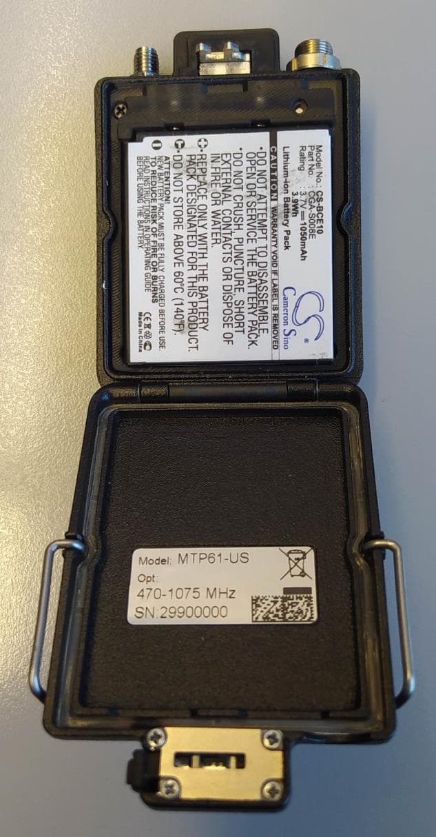
POUMTP61
Jul 23, 2023Wireless Microphone
Equipment Class
DWM - Part 15 Wireless Microphone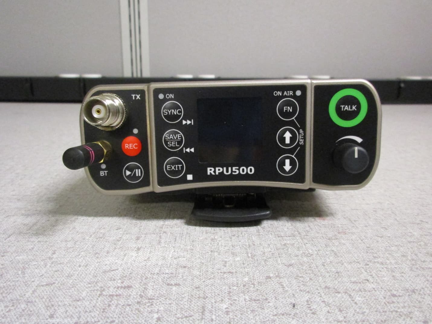
POURPU500
Sep 08, 2021Wireless Microphone
Equipment Class
DWM - Part 15 Wireless Microphone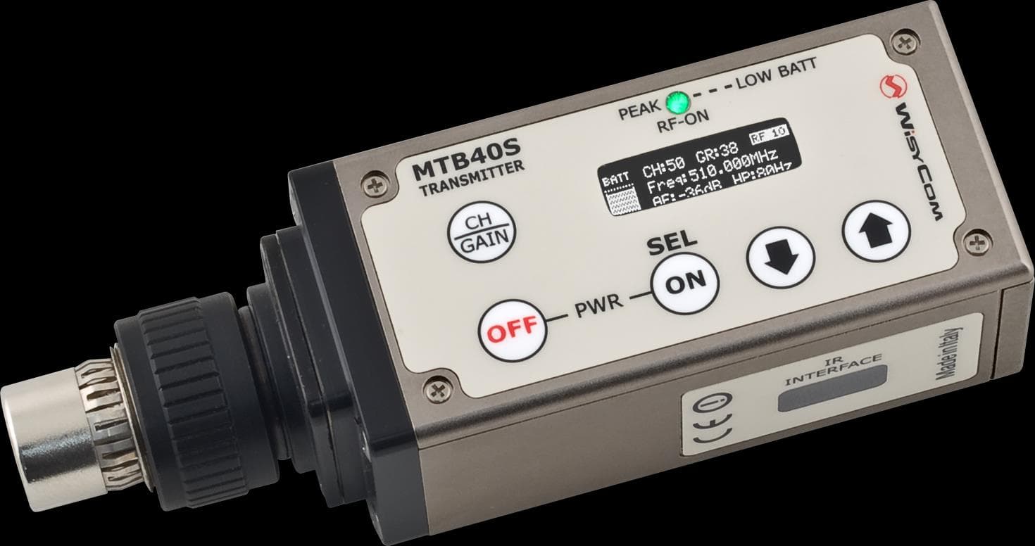
POUMTB40SUSX
Apr 20, 2015Plug on transmitter
Equipment Class
TBC - Licensed Broadcast Station Transmitter
POUMTK952N-0W2
Apr 11, 2015Dual Transmitter
Equipment Class
TNB - Licensed Non-Broadcast Station Transmitter
POUMTK952N-2W0
Apr 10, 2015Dual Transmitter
Equipment Class
TNB - Licensed Non-Broadcast Station Transmitter