POUMTP61Wireless Microphone
Wisycom s.r.l.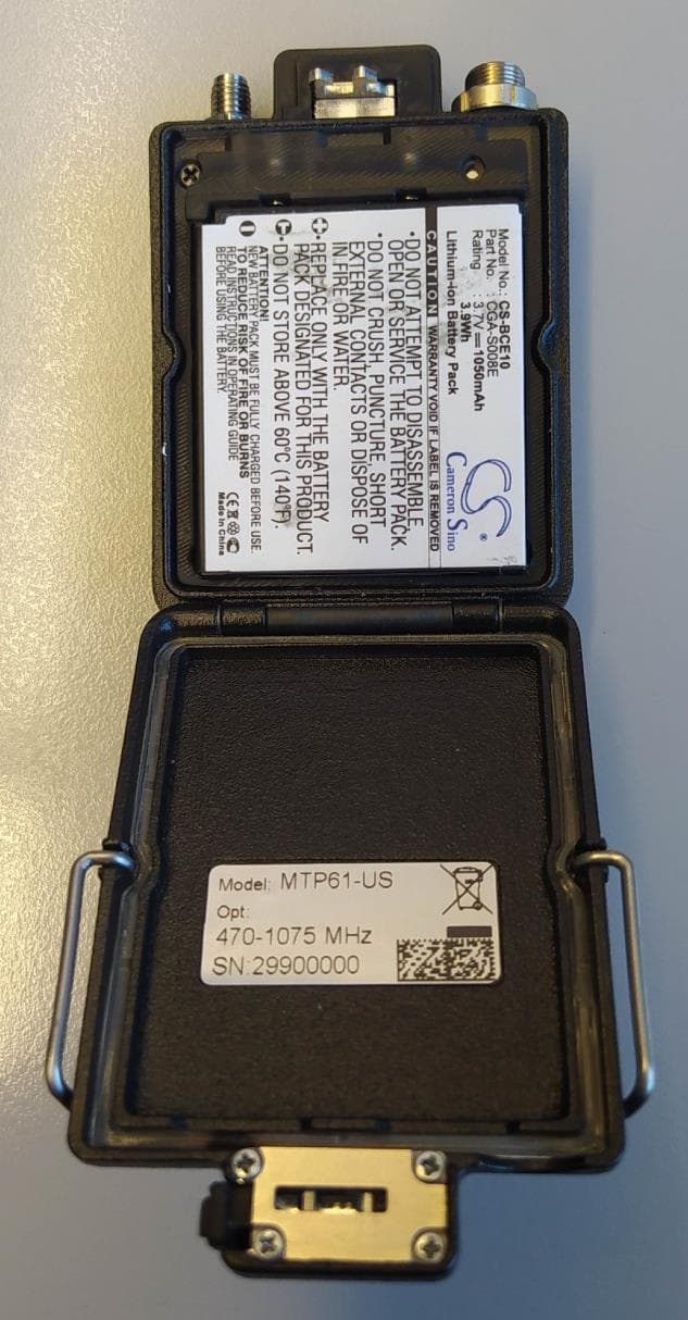
Click to zoom
Application Details
- Equipment Class
- DWM - Part 15 Wireless Microphone
- Date of Grant
- Jul 23, 2023
- Application Purpose
- Original Equipment
- Date of Application
- Jul 23, 2023
- Equipment Note
- Wireless Microphone
- Frequency Range
- 657.00000000 - 663.00000000
- Company
- Wisycom s.r.l.
- Country
- Italy
Documents & Files
Document Text
Text extracted from the exhibit documents filed with the FCC. Open a document above to read the original.
Users Manual
QUICK USER GUIDEQUICK USER GUIDE Main Accesories (find more information at Wisycom.com ) LBC61: Multiple battery charger (4 MTP61 + 4 batteries) + TX management + LTC CAUSBM5P: Cable from USB/A to mag- netic connector 5pin-M, lenght=1050mm for battery charging, TX management and LTC T i m e c o d e s y n c LBP61: rechargeable Lithium-ion battery Model CS-BCE10, Cameron Sino Part No. CGA-S008E. 3.7V, 1050 mAh, 3.9Wh LBP61: rechargeable Lithium-ion battery Model CS-BCE10, Part No. CGA-S008E 3.7V, 1050 mAh, 3.9Wh, Cameron Sino BCL61: spring loaded belt clip BCLW61: reversible wire belt clip MTP61-en-q03#ISTR-MTP61 (*)The Wisycom microphone pocket transmitter model MTP61 complies with the following requirements: FCC (Federal Communications Commission) Part 74. Operation is subject to the following two conditions: (1) This device may not cause harmful interference, and (2) This device must accept any interference received, including interference that may cause undesired operations. Changes or modification not expressly approved by the party responsible for compliance could void the user’s authority to operate the equipment. FCC ID can be found inside the battery compartment. This device complies with part 15 of the fcc rules. operation is subject to the following two conditions: (1) this device may not cause harmful interference, and (2) this device must accept any interference received, including interference that may cause undesired operation.Note: the grantee is not responsible for any changes or modifications not expressly approved by the party responsible for compliance. such modifications could void the user’s authority to operate the equipment. NOTE: This equipment has been tested and found to comply with the limits for a Class B digital device, pursuant to part 15 of the FCC Rules. These limits are designed to provide reasonable protection against harmful interference in a residential installation. This equipment generates uses and can radiate radio frequency energy and, if not installed and used in accordance with the instructions, may cause harmful interference to radio communications. However, there is no guarantee that interference will not occur in a particular installation. If this equipment does cause harmful interference to radio or television reception, which can be determined by turning the equipment off and on, the user is encouraged to try to correct the interference by one or more of the following measures: - Reorient or relocate the receiving antenna. - Increase the separation between the equipment and receiver. -Connect the equipment into an outlet on a circuit different from that to which the receiver is connected. -Consult the dealer or an experienced radio/TV technician for help. (**) EN This device complies with Industry Canada license-exempt RSS-123 and RSS-210 standard. Operation is subject to the following two conditions: (1) this device may not cause interference, and (2) this device must accept any interference, including interference that may cause undesired operation of the device. This radio transmitter IC: 11967A-MTP61 has been approved by Industry Canada to operate with the antenna types listed below with the maximum permissible gain and required antenna impedance for each antenna type indicated. Antenna types not included in this list, having a gain greater than the maximum gain indicated for that type, are strictly prohibited for use with this device. FR Le présent appareil est conforme aux CNR d’Industrie Canada applicables aux appareils radio exempts de licence RSS-123 et RSS-210. L’exploitation est autorisée aux deux conditions suivantes : (1) l’appareil ne doit pas produire de brouillage, et (2) l’utilisateur de l’appareil doit accepter tout brouillage radioélectrique subi, même si le brouillage est susceptible d’en compromettre le fonctionnement. Le présent émetteur radio IC: 11967A-MTP61a été approuvé par Industrie Canada pour fonctionner avec les types d’antenne é numérés ci-dessous et ayant un gain admissible maximal et l’impédance requise pour chaque type d’antenne. Les types d’antenne non inclus dans cette liste, ou dont le gain est supérieur au gain maximal indiqué, sont strictement interdits pour l’exploitation de l’émetteur. Antenna types (50 Ohm impedance, max gain 2.1dBi): AWSS-507: band 470-547 MHz, AWSS-590: band 547-663 MHz, AWSS30-950: band 940-960 MHz. This equipment complies has been evaluated for and shown compliant with the FCC and ISED RF Exposure limits. The unit of measurement for RF exposure is Specific Absorption Rate (SAR). The FCC SAR limits for is 1.6W/Kg per 1g of tissue The maximum SAR levels tested has been shown to be 0.85 W/kg at head with 0mm of separation distance from the body. This device operates on a no-interference, no-protection basis. Should the user seek to obtain protection from other radio services operating in the same TV bands, a radio license is required. For further details, consult Innovation, Science and Economic development Canada’s Client Procedures Circular CPC-2-1- 28, Voluntary Licensing of License-Exempt Wireless Microphones in TV Bands. MTP61MTP61 This guide is intended to assist you with initial quick setup and operation of your Wisycom product. You can refer to Wisycom Autorized Distributors for technical Support and information about service and repairs available in your area or contact us directly by email. Serial Number: Purchase Date: Download Documentation and Firmware Get declarations, user manual, specifica- tions and softwares on the download page: wisycom.com/products/d/MTP61 Keep up with Wisycom online Follow us on Facebook and Instagram. You can also subscribe on Youtube for more. wisycom.com/social Product Registration and Warranty Register your product to extend your warranty and receive update on latest firmware: wisycom.com/registration Conformity RADIO Directive 2014/53/ EU Radio Equipment Directive (RED) FCC-ID: POUMTP61 * UK Conformity IC: 11967A-MTP61 ** IC WISYCOM S.r.l. V…
Text truncated - open the document above for the full version.
External Photos
________________________________________________________________________________ WISYCOM S.r.l. V ia Tiepo lo, 7 /E 35019 Tombo lo (PD ) I taly tel. +39 .0424 382605 fax +39 .0424 38 2733 C ap . S oc. € .: 51 .000 i.v . VA T: IT 0 2765640244 R eg . Imp. V icenza e C .F .: 0276564024 4 Iscr izio ne al Reg istro A .E.E. n. IT091000 00006319 w eb : www.wisycom.com e-mail: sales@w isyco m.co m MTP61 - EXTERNAL PHOTOS ________________________________________________________________________________ WISYCOM S.r.l. V ia Tiepo lo, 7 /E 35019 Tombo lo (PD ) I taly tel. +39 .0424 382605 fax +39 .0424 38 2733 C ap . S oc. € .: 51 .000 i.v . VA T: IT 0 2765640244 R eg . Imp. V icenza e C .F .: 0276564024 4 Iscr izio ne al Reg istro A .E.E. n. IT091000 00006319 w eb : www.wisycom.com e-mail: sales@w isyco m.co m
ID Label/Location Info
________________________________________________________________________________ Wisycom srl - -address: Via Tiepolo, 7/E - 35019 Tombolo (PD) (Italy) Phone: +39 0424382605 - Email: [email protected] FCC ID: POUMTP61 Model: MTP61 Electronic label Wisycom S.R.L. guarantees the following rules: - the FCC identifier is visible on the display by accessing from the Main menu the Info> STD submenus: step 1: access submenu Info step 2: access submenu STD. - there are no special codes, accessories, or permissions to unlock the screen and accessing to the Info> STD menu. - the FCC identifier is clearly legible on the display without the aid of magnification. - the user manual reports clear information where find the FCC identifier. - the regulatory information is secured and implemented in a factory- set-unalterable format. ________________________________________________________________________________ Wisycom srl - -address: Via Tiepolo, 7/E - 35019 Tombolo (PD) (Italy) Phone: +39 0424382605 - Email: [email protected] - the regulatory information will be capable of being retrieved and displayed locally, and under the control of the end user in possession of the product. The following label is applied to the packaging:
Internal Photos
________________________________________________________________________________ WISYCOM S.r.l. V ia Tiepo lo, 7 /E • 35019 Tombo lo (PD ) Italy • tel. +39 .0424 382605 • fax +39 .0424 38 2733 C ap . S oc. € .: 51 .000 i.v . • VA T: IT 0 2765640244 • R eg . Imp. V icenza e C .F .: 0276564024 4 Iscr izio ne al Reg istro A .E.E. n. IT091000 00006319 w eb : www.wisycom.com • e-mail: sales@w isyco m.co m MTP61 - INTERNAL PHOTOS MTP61 consists of 2 boards: • Main • Battery recharge Main board: They are IC modules (oscillators) ________________________________________________________________________________ WISYCOM S.r.l. V ia Tiepo lo, 7 /E • 35019 Tombo lo (PD ) Italy • tel. +39 .0424 382605 • fax +39 .0424 38 2733 C ap . S oc. € .: 51 .000 i.v . • VA T: IT 0 2765640244 • R eg . Imp. V icenza e C .F .: 0276564024 4 Iscr izio ne al Reg istro A .E.E. n. IT091000 00006319 w eb : www.wisycom.com • e-mail: sales@w isyco m.co m Battery recharge board:
RF Exposure Info
© 2023 RF Exposure Lab, LLC This report shall not be reproduced except in full without the written approval of RF Exposure Lab, LLC. 802 N. Twin Oaks Valley Road, Suite 105 • San Marcos, CA 92069 • U.S.A. TEL (760) 471-2100 • FAX (760) 471-2121 http://www.rfexposurelab.com CERTIFICATE OF COMPLIANCE SAR EVALUATION Wisycom SRL Dates of Test: April 3, 2023 Via Tiopolo, 7/E. Test Report Number: SAR.20211001 Tombolo, Italy 35019 Lab Designation Number: US1195 (FCC); US0194 (ISED) This wireless mobile and/or portable device has been shown to be compliant for localized specific absorption rate (SAR) for controlled environment limits specified in ANSI/IEEE Std. C95.1-1992 and had been tested in accordance with the measurement procedures specified in IEEE 1528-2013, IEC62209- 1528:2020 and RSS-102 Issue 5 (See test report). I attest to the accuracy of the data. All measurements were performed by myself or were made under my supervision and are correct to the best of my knowledge and belief. I assume full responsibility for the completeness of these measurements and vouch for the qualifications of all persons taking them. RF Exposure Lab, LLC certifies that no party to this application is subject to a denial of Federal benefits that includes FCC benefits pursuant to Section 5301 of the Anti-Drug Abuse Act of 1988, 21 U.S.C. 853(a). Jay M. Moulton Vice President Testing Cert. # 2387.01 FCC ID: POUMTP61 IC Certificate: 11967A-MTP61 Model(s): MTP61 Contains BT Module: Silab Model BGM220SC22HNA2, FCC ID: QOQ-BGM220S2, IC: 5123A-BGM220S2 Test Sample: Engineering Unit Same as Production Serial Number: 29900000 Equipment Type: Wireless Body Worn Microphone Classification: Portable Transmitter Next to Body TX Frequency Range: 470.025 – 607.975 MHz; 614.025 – 615.975 MHz; 653.025 – 662.975 MHz; 941.525 – 951.975 MHz; 952.875 – 956.225 MHz; 956.475 – 959.825 MHz Frequency Tolerance: ± 2.5 ppm Maximum RF Output: 470 – 608 MHz – 20.00 dBm, 600 MHz – 13.01 dBm, 900 MHz – 20.00 dBm Conducted Signal Modulation: FM Body Worn Accessories: Belt Clip Audio Accessories: Standard Speaker MIC Antenna: 507 (470-547 MHz), 590 (547-663 MHz), 950 (940-960 MHz) Battery: Li-ion Model CS-BCE10 Application Type: Certification FCC Rule Parts: Part 2, 74, 90 Industry Canada: RSS-102 Issue 5, Safety Code 6 KDB Test Methodology: KDB 447498 D01 v06 Maximum SAR Value: 0.85 W/kg Reported Simultaneous SAR Value: 0.92 W/kg Reported Separation Distance: 0 mm for Body Report Number: SAR.20230401 © 2023 RF Exposure Lab, LLC Page 2 of 79 This report shall not be reproduced except in full without the written approval of RF Exposure Lab, LLC. Table of Contents 1. Introduction ........................................................................................................................ 4 SAR Definition [5] ................................................................................................................... 5 2. SAR Measurement Setup ................................................................................................... 6 Robotic System ...................................................................................................................... 6 System Hardware ................................................................................................................... 6 System Electronics ................................................................................................................. 7 Probe Measurement System .................................................................................................. 7 3. Probe and Dipole Calibration .............................................................................................15 4. Phantom & Simulating Tissue Specifications .....................................................................16 Head & Body Simulating Mixture Characterization ................................................................16 5. ANSI/IEEE C95.1 – 1992 RF Exposure Limits [2] ..............................................................17 Uncontrolled Environment .....................................................................................................17 Controlled Environment .........................................................................................................17 6. Measurement Uncertainty .................................................................................................18 7. System Validation..............................................................................................................19 Tissue Verification .................................................................................................................19 Test System Verification ........................................................................................................19 8. SAR Test Data Summary ..................................................................................................20 Procedures Used To Establish Test Signal ...........................................................................20 Device Test Condition ...........................................................................................................20 SAR Data Summary – Body Measurements .............................................................................23 9. Test Equipment List ...........................................................................................................25 10. Conclusion ....................................................................................................................26 11. References ....................................................................................................................27 Appendix A – System Validation Plots and Data .......................................................................28 Appendix B – SAR Test Data Plots ...........................................................................................33 Appendi…
Text truncated - open the document above for the full version.
Test Report
Wisycom srl - -address: Via Tiepolo, 7/E - 35019 Tombolo (PD) (Italy) Phone: +39 0424382605 - Email: [email protected] Wisycom MTP61 Wireless Microphone - Antenna Characteristics Data: 12 July 2023 Author: Alberto Vigato (Senior R&D Scientist), Nadia Sbrissa (Sales Engineer) Wisycom srl - -address: Via Tiepolo, 7/E - 35019 Tombolo (PD) (Italy) Phone: +39 0424382605 - Email: [email protected] Table of contents Wisycom MTP61 Wireless Microphone - Antenna Characteristics ................ 1 Brief description: .................................................................................. 3 Antenna specifications: .......................................................................... 4 Radiation pattern: ................................................................................. 5 Antenna code 507 (range 470- 547 MHz): ............................................. 5 Antenna code 590 (range 547-663 MHz): .............................................. 6 Antenna code 950 (range 940 - 960 MHz): ............................................ 7 Wisycom srl - -address: Via Tiepolo, 7/E - 35019 Tombolo (PD) (Italy) Phone: +39 0424382605 - Email: [email protected] Brief description: The MTP61 is a wireless pocket transmitter specially designed for professional wireless microphone applications. It operates in the UHF band (470-663 MHz + 940-1075 MHz). To cover the whole frequency range of MTP61, the transmitter is supplied with the following whip antennas: Code Description AWSS-507 Whip antenna with SSMA connector, range 470-547 MHz AWSS-590 Whip antenna with SSMA connector, range 547-663 MHz AWSS-950 Whip antenna with SSMA connector, range 940-960 MHz Each antenna is identified with the code (3 digit) which is approximatively the central frequency of the range. According to the frequency set on the transmitter MTP61, the firmware of the transmitter suggests the right code of antenna to use. The antenna must be attached directly to the SSMA connector on the MTP61 transmitter. Wisycom srl - -address: Via Tiepolo, 7/E - 35019 Tombolo (PD) (Italy) Phone: +39 0424382605 - Email: [email protected] Antenna specifications: Index Component Material Surface treatment ① SSMA connector brass nickel ② wire stainless steel and urethane black The antenna is cut in Wisycom factory according to the operative frequency range: Code Lenght AWSS-507 139 mm AWSS-590 115 mm AWSS-950 73 mm The length of cuts is inclusive of the SSMA connector (as shown in the picture) L Wisycom srl - -address: Via Tiepolo, 7/E - 35019 Tombolo (PD) (Italy) Phone: +39 0424382605 - Email: [email protected] Radiation pattern: Antenna code 507 (range 470- 547 MHz): Wisycom code: AWSS-507 Max Gain [dBi]: +0.8 Temperature condition: +22°C Voltage condition: 3.7V Frequency: 510 MHz Antenna code 507 - 3D radiation patterns and scale Wisycom srl - -address: Via Tiepolo, 7/E - 35019 Tombolo (PD) (Italy) Phone: +39 0424382605 - Email: [email protected] Antenna code 590 (range 547-663 MHz): Wisycom code: AWSS-590 Max Gain [dBi]: +1 Temperature condition: +22°C Voltage condition: 3.7V Frequency: 600 MHz Antenna code 590 - 3D radiation patterns and scale Wisycom srl - -address: Via Tiepolo, 7/E - 35019 Tombolo (PD) (Italy) Phone: +39 0424382605 - Email: [email protected] Antenna code 950 (range 940 - 960 MHz): Wisycom code: AWSS-950 Max Gain [dBi]: +1.2 Temperature condition: +22°C Voltage condition: 3.7V Frequency: 950 MHz Antenna code 950 - 3D radiation patterns and scale
Test Report
Timco Test Report # TR_7197-23_FCC PART 15.236_ Revision: 2 An IIA Company Te s t Report – FCC PART 15.236 LOW POWER UNLICENSED WIRELESS MICROPHONE Applicant: Wisycom s.r.l. Approved for Release By: Signature: Name & Title: Bruno Clavier, General Manager Date of Signature 07/7/2023 This test report shall not be reproduced except in full without the written and signed permission of Timco Engineering Inc. (IIA). This test report relates only to the items tested as identified and is not valid for any subsequent changes or modifications made to the equipment under test. Timco Engineering, Inc., an IIA Company 849 NW State Road 45, Newberry, Florida 32669 (352) 472-5500 / [email protected] Page 2 of 48 This test report shall not be reproduced except in full without the written and signed permission of Timco Engineering Inc. (IIA). Table of Contents 1. CUSTOMER INFORMATION ........................................................................................................................................................................... 4 1.1 TEST RESULT SUMMARY ............................................................................................................................................................................................4 2. LOCATION OF TESTING ................................................................................................................................................................................. 5 2.1 TEST LABORATORY .................................................................................................................................................................................................... 5 2.2 TESTING WAS PERFORMED, REVIEWED BY ................................................................................................................................................................ 6 3. TEST SAMPLE(S) (EUT/DUT) ........................................................................................................................................................................... 7 3.1 DESCRIPTION OF THE EUT ........................................................................................................................................................................................ 7 3.2 CONFIGURATION OF EUT ......................................................................................................................................................................................... 8 3.3 TEST SETUP OF EUT .................................................................................................................................................................................................. 8 4. TEST METHODS & APPLICABLE REGULATORY LIMITS ............................................................................................................................ 9 4.1 TEST METHODS/STANDARDS/GUIDANCE ................................................................................................................................................................ 9 5. MEASUREMENT UNCERTAINTY .................................................................................................................................................................... 9 6. ENVIRONMENTAL CONDITIONS ................................................................................................................................................................. 9 7. LIST OF TEST EQUIPMENT AND TEST FACILITY ...................................................................................................................................... 10 8. TEST RESULTS ................................................................................................................................................................................................. 12 8.1 RF POWER OUTPUT ........................................................................................................................................................................................... 13 8.1.1 Test Data: RF Power Output Measurement Table, 470.075 MHz ............................................................................................. 14 8.1.2 Test Data: RF Power Output Measurement Table, 555.000 MHz ............................................................................................. 15 8.1.3 Test Data: RF Power Output Measurement Table, 607.925 MHz ............................................................................................. 16 8.1.4 Test Data: RF Power Output Measurement Table, 614.075 MHz ............................................................................................. 17 8.1.5 Test Data: RF Power Output Measurement Table, 615.925 MHz ............................................................................................. 18 8.1.6 Test Data: RF Power Output Measurement Table, 662.925 MHz ............................................................................................. 19 8.2 OCCUPIED BANDWIDTH ................................................................................................................................................................................ 20 8.2.1 Test Data: 99% Occupied Bandwidth Measurement Plot, 470.075 MHz ............................................................................... 21 8.2.2 Test Data: 99% Occupied Bandwidth Measurement Plot, 555.000 MHz ............................................................................... 22 8.2.3 Test Data: 99% Occupied Bandwidth Measurement Plot, 607.925 MHz .............................................................................. 23 8.2.4 Test Data: 99% Occupied Bandwidth Measurement Plot, 614.075 MHz ............................................................................... 24 8.2.5 Test Data: 99% Occupied Bandwidth Measurement Plot, 615.925 MHz .........................................…
Text truncated - open the document above for the full version.
Test Setup Photos
ANNEX B – Test Setup Photograph Exhibit 7197-23 & 7198-23 Model: MTP61 FCC ID: POUMTP61 IC: 11967A-MTP61 Conducted Test Setup Radiated Testing, Table Setup Radiated Testing, Below 1 GHz Radiated Testing, Below 1 GHz #2 Radiated Testing, Above 1 GHz Frequency Stability Testing
Contact Information
Applicant
Enzo Frigo(CTO)
Test Firm
Timco Engineering, Inc.Bruno Clavier
Technical Specifications
| # | Rule Parts | Frequency Range | Power Output |
|---|---|---|---|
| 3 | 15C | 657 MHz - 663 MHz | 23.00 mW |
Other Applications from Wisycom s.r.l.
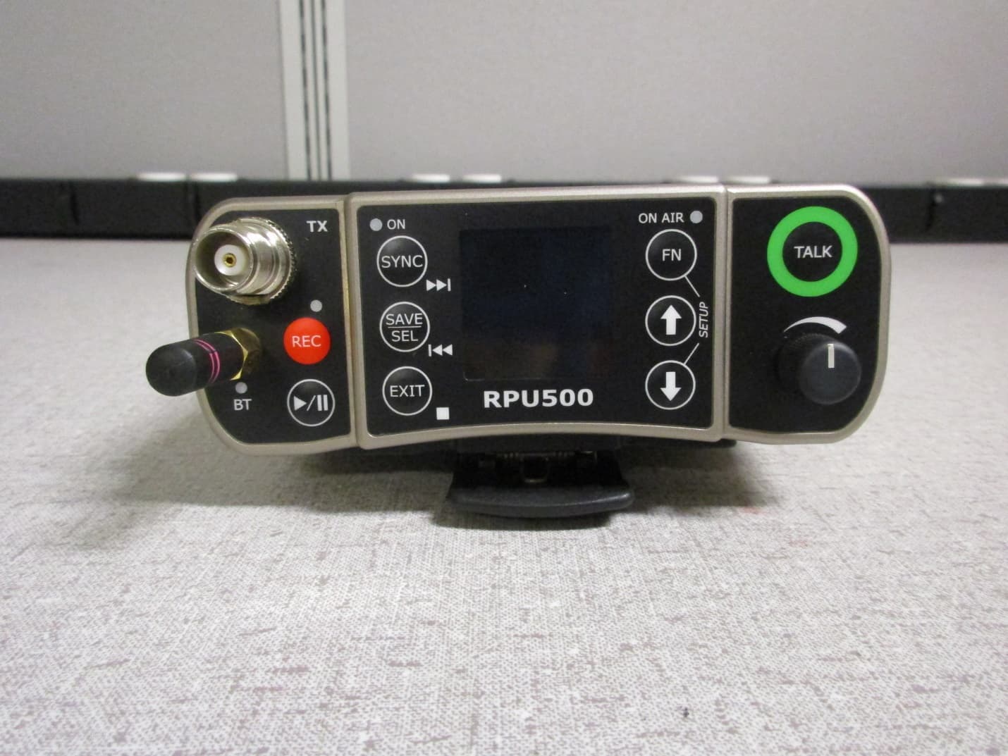
POURPU500
Sep 08, 2021Wireless Microphone
Equipment Class
DWM - Part 15 Wireless Microphone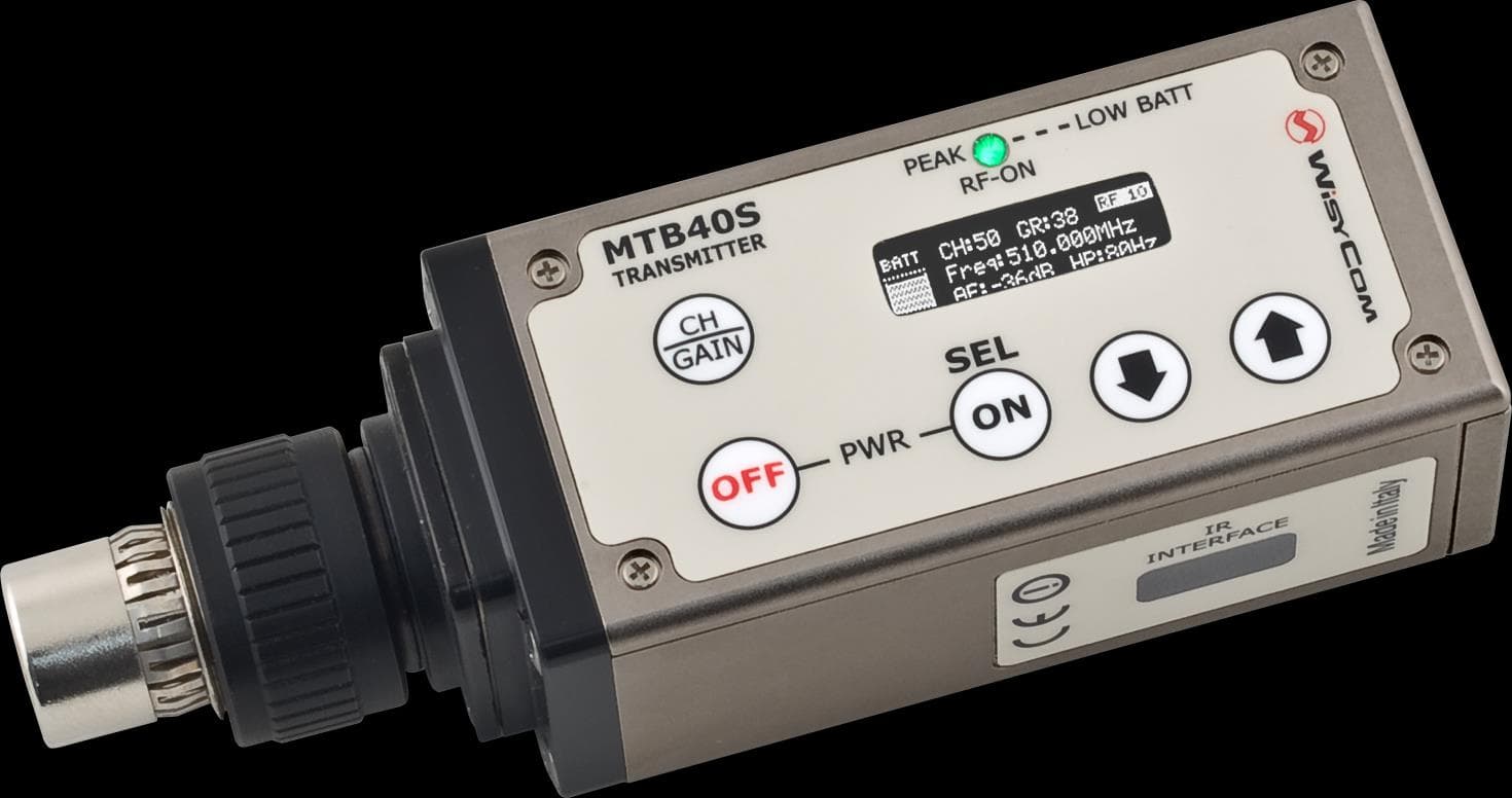
POUMTB40SUSX
Apr 20, 2015Plug on transmitter
Equipment Class
TBC - Licensed Broadcast Station Transmitter
POUMTK952N-0W2
Apr 11, 2015Dual Transmitter
Equipment Class
TNB - Licensed Non-Broadcast Station Transmitter
POUMTK952N-2W0
Apr 10, 2015Dual Transmitter
Equipment Class
TNB - Licensed Non-Broadcast Station Transmitter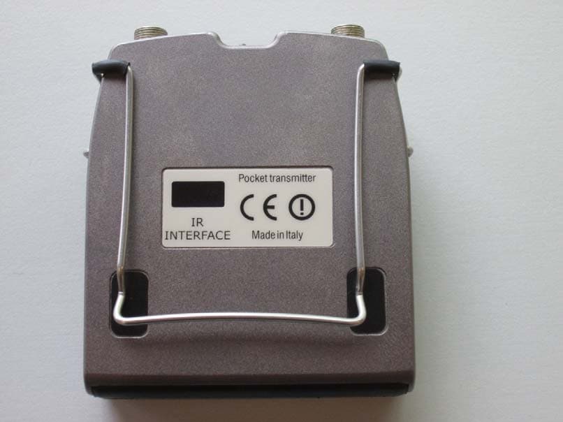
POUMTP40SUSX
Jul 01, 2014Wideband bodypack transmitter
Equipment Class
TBT - Licensed Broadcast Transmitter Worn on Body