POURPU500Wireless Microphone
Wisycom s.r.l.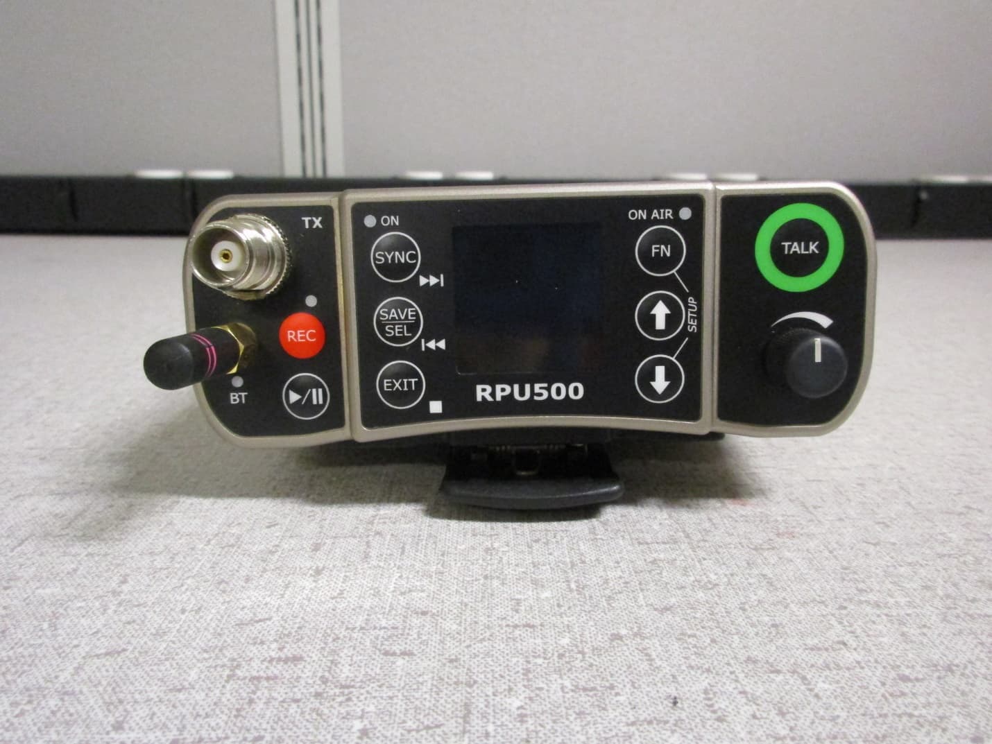
Click to zoom
Application Details
- Equipment Class
- DWM - Part 15 Wireless Microphone
- Date of Grant
- Sep 08, 2021
- Application Purpose
- Original Equipment
- Date of Application
- Sep 08, 2021
- Equipment Note
- Wireless Microphone
- Frequency Range
- 657.00000000 - 663.00000000
- Company
- Wisycom s.r.l.
- Country
- Italy
Documents & Files
Document Text
Text extracted from the exhibit documents filed with the FCC. Open a document above to read the original.
Users Manual
RPU500-Tx User Manual High-power, reporter portable unit Rev.06 (ref. FW v1.4) Date: 01 September 2021 RPU500-Tx User Manual 2 SAFETY INSTRUCTION Read this safety instruction and the manual first Follow all instructions and information. Do not lose this manual. The unit is designed for Professional Use only Do not use this apparatus under the rain or near the water. Do not install the apparatus near heaters or in hot environments, do not use outside the operating temperature range. Do not open the apparatus, only qualified service technician are enabled to operate on it. The apparatus needs servicing when it is not properly working or is damaged by liquids, moisture or other objects are fallen in the apparatus. Use only accessories or replacement parts authorized or specified by the manufacturer. Clean the apparatus only with dry cloths, do not use liquids. Report the serial number and the purchasing date in front of the manual. It is needed to have proper replacement parts or accessories from the manufacturer. When replacement parts are needed, use only replacement parts authorized from the manufacturer. Substitution with not authorized parts could result in electric shock, hazards or fire. Keep attention on all the labels with warnings or hazards on the apparatus. THE DEVICE CAN ONLY BE WEAR WITH THE BELT CLIP PROVIDED BY WISYCOM (code: BCL500), It is not possible to wear other belt clips NOT authorized by Wisycom RPU500-Tx User Manual 3 PRODUCT OVERVIEW FRONT ❶ TNC antenna connector ❽ TALK button (to activate TALK transmission) ❷ REC button (for audio recording on SD card) ❾ VOLUME knob ❸ Play audio from SD card ❿ SAVE or SEL button ❹ Led ON (green when transmitter is on) ⓫ EXIT button ❺ SYNC button (for automatic synchronization with Wisycom RX) ⓬ DOWN arrow button ❻ FN button (for quick menu selection) ⓭ UP arrow button ❼ ON AIR led (green when transmission is active) ❶ ❷ ❸ ❹ ❺ ❿ ⓫ ❻ ❼ ⓬ ⓭ ❽ ❾ RPU500-Tx User Manual 4 REAR ❶ battery compartment latch ❼ Lazy 2 button* ❷ battery compartment ❽ Lazy 3 button* ❸ SD card slot ❾ XLR-3pin connector for MIC/LINE audio input ❹ USB-C connector (for power and control) ❿ Hirose 4-pin power supply connector 10-18V (pin1:GND, pin4:+Vdc) ❺ ON/OFF switch ⓫ waterproof jack 3.5mm (audio output or Aux input) ❻ Lazy 1 button* ⓬ waterproof jack 3.5mm (audio output) ❶ ❾ ❿ ❻ ❼ ❽ ⓬ ⓫ ❸ ❹ ❺ ❷ RPU500-Tx User Manual 5 QUICK SETUP 1. unlatch the battery compartment latch at the bottom of the device 2. insert the battery 3. move the wireless power switch in “I” position to power on the device 4. the front LED lights up green and 5. the display switch on 6. connect the XLR MIC (If required enables Phantom 12V/48V thru Audio>Phantom menu) 7. set frequency thru RF>FREQ menu 8. connect the antenna (according to set frequency) 9. set RF Power thru RF>Power menu 10. push the TALK button to activate transmission ❹ ❺ ❶ ❷ ❸ ❻ RPU500-Tx User Manual 6 DISPLAY This is the first menu displayed after power up Status of Transmission: OFF: RF transmission is OFF ST-BY [Stand-by]: It is the status of the transmitter after the power on when “TX Start” menu is set to MUTE. The transmitter sends the carrier with an auxiliary tone (@28kHz) without the audio (The TX occupies the channel) MRK980 receiver puts in MUTE the audio output A X icon is showed to indicate that the audio is muted ON-AIR: RF transmission is active with audio and an auxiliary sub-tone. According to the pushed button the auxiliary sub-tone is different and the display show a different icon: o T when Talk button is pushed (sub-tone@ ̴33kHz) o 1 when Lazy 1 button is pushed (sub-tone@ 32687 Hz*) o 2 when Lazy 2 button is pushed (sub-tone@ 32869 Hz*) o 3 when Lazy 3 button is pushed (sub-tone@ 33013 Hz*) *Standard Wisycom sub-tone. Other sub-tones can be configured in Wisycom factory In the Talk mode, just press the Talk button once and the transmission remains active until the button is pressed again. In Lazy mode, on the other hand, it is necessary to hold down the Lazy buttons to keep the transmission active. Wisycom receiver MRK980 detects the sub-tones and pass this information to the mixer (via Ethernet / Ember + protocol). From the mixer it is therefore possible to configure the audio routing. Name of transmitter Level of RF Power Compander Level of Battery % and time (hours :minutes) Time Level of audio input Frequency Group & Channel Modulation Bandwidth (Wide/Narrow) Status of Transmission RPU500-Tx User Manual 7 MENU Using navigation buttons it is possible to quick & easy navigate through the RPU500 menu: SAVE/SEL to enter on a sub-menu or change a parameter EXIT to exit from a sub-menu or exit from a parameter modification Arrow up/down to circle on the same level SAVE/SEL press and hold to save the modified parameters Product overview RPU500-Tx User Manual 8 NOTE: Features not still implemented (reference firmware v1.4): SD card recording Bluetooth They will soon be available with a next firmware update. RPU500-Tx User Manual 9 RF menu: Thanks to the RF menu is possible to configure all the RF parameters related to the transmission. Freq. menu: In this menu current channel/group and frequencies can be setup. Channel frequency (in 5kHz step) Group number (1 to 40) and group name (8 char.) Channel number (0 to 60) Max power allows at set frequency Use the selector and arrows to change values and SAVE to confirm. Sync group is a quick self-settable channel synchronized by receiver (with SYNC group, on the top right of the display is shown the name of the synchronized receiver). NOTE: The device has 40 groups of 60 channels each. Connecting with computer with WISYCOM MANAGER software, it is possible to hide single channels or even complete groups of channels: once hidden those items are not shown anymore on the channels or groups selection. To show channels or groups hidden use again the WISYCOM MANAGER software. Using this software it is also possible to lock cha…
Text truncated - open the document above for the full version.
External Photos
Applicant: Wisycom SRL FCC ID: POURPU500 IC: 11967A-RPU500 EXTERNAL PHOTOS FRONT VIEW REAR VIEW TOP VIEW BOTTOM VIEW LEFT SIDE VIEW RIGHT SIDE VIEW
ID Label/Location Info
________________________________________________________________________________ Wisycom srl - -address: Via Tiepolo, 7/E - 35019 Tombolo (PD) (Italy) Phone: +39 0424382605 - Email: [email protected] FCC ID: POURPU500 Model number: RPU500 Electronic label Wisycom S.R.L. guarantees the following rules: - the FCC identifier is visible on the display when the device is switched on and it is also available by accessing from the Main menu the Options> Info> Regulatory submenus - the user manual reports clear information where find the FCC identifier
Internal Photos
________________________________________________________________________________ WISYCOM S.r.l. V ia Tiepo lo, 7 /E 35019 Tombo lo (PD ) I taly tel. +39 .0424 382605 fax +39 .0424 38 2733 C ap . S oc. € .: 51 .000 i.v . VA T: IT 0 2765640244 R eg . Imp. V icenza e C .F .: 0276564024 4 Iscr izio ne al Reg istro A .E.E. n. IT091000 00006319 w eb : www.wisycom.com e-mail: sales@w isyco m.co m RPU500 - INTERNAL PHOTOS RPU500 consists of 5 PCB: RF Display Jack Battery XLR RF PCB top: ________________________________________________________________________________ WISYCOM S.r.l. V ia Tiepo lo, 7 /E 35019 Tombo lo (PD ) I taly tel. +39 .0424 382605 fax +39 .0424 38 2733 C ap . S oc. € .: 51 .000 i.v . VA T: IT 0 2765640244 R eg . Imp. V icenza e C .F .: 0276564024 4 Iscr izio ne al Reg istro A .E.E. n. IT091000 00006319 w eb : www.wisycom.com e-mail: sales@w isyco m.co m RF PCB bottom: DISPLAY PCB top: ________________________________________________________________________________ WISYCOM S.r.l. V ia Tiepo lo, 7 /E 35019 Tombo lo (PD ) I taly tel. +39 .0424 382605 fax +39 .0424 38 2733 C ap . S oc. € .: 51 .000 i.v . VA T: IT 0 2765640244 R eg . Imp. V icenza e C .F .: 0276564024 4 Iscr izio ne al Reg istro A .E.E. n. IT091000 00006319 w eb : www.wisycom.com e-mail: sales@w isyco m.co m DISPLAY PCB bottom: JACK PCB top: JACK PCB bottom: ________________________________________________________________________________ WISYCOM S.r.l. V ia Tiepo lo, 7 /E 35019 Tombo lo (PD ) I taly tel. +39 .0424 382605 fax +39 .0424 38 2733 C ap . S oc. € .: 51 .000 i.v . VA T: IT 0 2765640244 R eg . Imp. V icenza e C .F .: 0276564024 4 Iscr izio ne al Reg istro A .E.E. n. IT091000 00006319 w eb : www.wisycom.com e-mail: sales@w isyco m.co m BATTERY PCB bottom: XLR PCB top: XLR PCB bottom:
RF Exposure Info
© 2021 RF Exposure Lab, LLC This report shall not be reproduced except in full without the written approval of RF Exposure Lab, LLC. 802 N. Twin Oaks Valley Road, Suite 105 • San Marcos, CA 92069 • U.S.A. TEL (760) 471-2100 • FAX (760) 471-2121 http://www.rfexposurelab.com CERTIFICATE OF COMPLIANCE SAR EVALUATION Wisycom SRL Dates of Test: June 28-30, 2021 Via Tiepolo, 7/E Test Report Number: SAR.20210703 Tombolo, Italy 35019 Revision A This wireless mobile and/or portable device has been shown to be compliant for localized specific absorption rate (SAR) for controlled environment limits specified in ANSI/IEEE Std. C95.1-1992 and had been tested in accordance with the measurement procedures specified in IEEE 1528-2003, IEC62209 and RSS-102 Issue 5 (See test report). I attest to the accuracy of the data. All measurements were performed by myself or were made under my supervision and are correct to the best of my knowledge and belief. I assume full responsibility for the completeness of these measurements and vouch for the qualifications of all persons taking them. RF Exposure Lab, LLC certifies that no party to this application is subject to a denial of Federal benefits that includes FCC benefits pursuant to Section 5301 of the Anti-Drug Abuse Act of 1988, 21 U.S.C. 853(a). Jay M. Moulton Vice President Testing Cert. # 2387.01 FCC ID: POURPU500 Model(s): RPU500 Test Sample: Engineering Unit Same as Production Serial Number: 01500109 Equipment Type: Wireless Body Worn Microphone Classification: Portable Transmitter Next to Body TX Frequency Range: 174 – 216 MHz; 450 – 451 MHz; 455 – 456 MHz; 470 – 608 MHz; 614 – 616 MHz; 653 – 663 MHz; 941.5 – 952 MHz; 952.85 – 956.25 MHz; 956.45 – 959.85 MHz Frequency Tolerance: ± 2.5 ppm Maximum RF Output: 220 MHz – 14.77 dBm, 450 MHz – 30.00 dBm, 470 – 608 MHz – 23.98 dBm, 600 MHz – 10.79 dBm, 900 MHz – 30.00 dBm Conducted Signal Modulation: FM Body Worn Accessories: Belt Clip Audio Accessories: Standard Speaker MIC Antenna: AWT500-180 (170-188 MHz), AWT500-197 (188-206 MHz), AWT500-213 (206-220 MHz), AWT500-229 (220-238 MHz), AWT500-458 (440-480 MHz), AWT500-494 (470-517 MHz), AWT500-540 (515-563 MHz), AWT500-590 (562-609 MHz), AWT500-625 (609-645 MHz), AWT500-670 (645-696 MHz), AWT500-730 (715-744 MHz), AWT500-950 (940-960 MHz) Battery: Standard (Model 100498-08) Application Type: Certification FCC Rule Parts: Part 2, 74, 90 KDB Test Methodology: KDB 447498 D01 v06 Maximum SAR Value: 0.89 W/kg Reported Separation Distance: 0 mm for Body Report Number: SAR.20210703 © 2021 RF Exposure Lab, LLC Page 2 of 93 This report shall not be reproduced except in full without the written approval of RF Exposure Lab, LLC. Table of Contents 1. Introduction ........................................................................................................................ 4 SAR Definition [5] ................................................................................................................... 5 2. SAR Measurement Setup ................................................................................................... 6 Robotic System ...................................................................................................................... 6 System Hardware ................................................................................................................... 6 System Electronics ................................................................................................................. 7 Probe Measurement System .................................................................................................. 7 3. Probe and Dipole Calibration .............................................................................................15 4. Phantom & Simulating Tissue Specifications .....................................................................16 Head & Body Simulating Mixture Characterization ................................................................16 5. ANSI/IEEE C95.1 – 1992 RF Exposure Limits [2] ..............................................................17 Uncontrolled Environment .....................................................................................................17 Controlled Environment .........................................................................................................17 6. Measurement Uncertainty .................................................................................................18 7. System Validation..............................................................................................................19 Tissue Verification .................................................................................................................19 Test System Verification ........................................................................................................19 8. SAR Test Data Summary ..................................................................................................20 Procedures Used To Establish Test Signal ...........................................................................20 Device Test Condition ...........................................................................................................20 SAR Data Summary – Body Measurements .............................................................................23 9. Test Equipment List ...........................................................................................................24 10. Conclusion ....................................................................................................................25 11. References ....................................................................................................................26 Appendix A – System Validation Plots and Data .......................................................................27 Appendix B – SAR Test Data Plots .............................................…
Text truncated - open the document above for the full version.
Test Report
Timco Test Report # TR_2949-21 FCC PART 15.236_2 Revision: 2 Issue Date: 9/2/2021 Final Test Date: 7/1/2021 An IIA Company Te s t Report – FCC PART 15.236 LOW POWER LICENSED WIRELESS MICROPHONE Prepared For: Wisycom Approved for Release By: Signature: Name & Title: Bruno Clavier, General Manager Date of Signature 7/2/2021 This test report shall not be reproduced except in full without the written and signed permission of Timco Engineering Inc. (IIA). This test report relates only to the items tested as identified and is not valid for any subsequent changes or modifications made to the equipment under test. Timco Engineering, Inc., an IIA Company 849 NW State Road 45, Newberry, Florida 32669 (352) 472-5500 / [email protected] Page 2 of 50 This test report shall not be reproduced except in full without the written and signed permission of Timco Engineering Inc. (IIA). Table of Contents 1. CUSTOMER INFORMATION ........................................................................................................................................................................... 4 1.1 TEST RESULT SUMMARY ............................................................................................................................................................................................4 2. LOCATION OF TESTING ................................................................................................................................................................................. 5 2.1 TEST LABORATORY .................................................................................................................................................................................................... 5 2.2 TESTING WAS PERFORMED, REVIEWED BY ................................................................................................................................................................ 6 3. TEST SAMPLE(S) (EUT/DUT) ........................................................................................................................................................................... 7 3.1 DESCRIPTION OF THE EUT ........................................................................................................................................................................................ 7 3.2 CONFIGURATION OF EUT ......................................................................................................................................................................................... 8 3.3 TEST SETUP OF EUT .................................................................................................................................................................................................. 8 4. TEST METHODS & APPLICABLE REGULATORY LIMITS ............................................................................................................................ 9 4.1 TEST METHODS/STANDARDS/GUIDANCE ................................................................................................................................................................ 9 5. MEASUREMENT UNCERTAINTY .................................................................................................................................................................... 9 6. ENVIRONMENTAL CONDITIONS ................................................................................................................................................................. 9 7. LIST OF TEST EQUIPMENT AND TEST FACILITY ...................................................................................................................................... 10 8. TEST RESULTS .................................................................................................................................................................................................. 11 8.1 RF POWER OUTPUT ........................................................................................................................................................................................... 12 8.1.1 Test Data: RF Power Output Measurement Table ........................................................................................................................ 12 8.2 OCCUPIED BANDWIDTH ................................................................................................................................................................................. 16 8.2.1 Test Data: 99% Occupied Bandwidth Measurement Plot, 174 MHz ........................................................................................ 17 8.2.2 Test Data: 99% Occupied Bandwidth Measurement Plot, 200 MHz ....................................................................................... 18 8.2.3 Test Data: 99% Occupied Bandwidth Measurement Plot, 215 MHz ........................................................................................ 19 8.2.4 Test Data: 99% Occupied Bandwidth Measurement Plot, 470 MHz ...................................................................................... 20 8.2.5 Test Data: 99% Occupied Bandwidth Measurement Plot, 555 MHz ........................................................................................ 21 8.2.6 Test Data: 99% Occupied Bandwidth Measurement Plot, 608 MHz ....................................................................................... 22 8.2.1 Test Data: 99% Occupied Bandwidth Measurement Plot, 614.5 MHz ................................................................................... 23 8.2.2 Test Data: 99% Occupied Bandwidth Measurement Plot, 657 MHz ...................................................................................... 24 8.2.3 Test Data: 99% Occupied Bandwidth Measurement Plot, 662 MHz ....................................................................................... 25 8.2.4 Test Data: 26dB Occupied Bandwidth Measurement Plot,…
Text truncated - open the document above for the full version.
Test Setup Photos
ANNEX B – Test Setup Photograph Exhibit Wisycom SRL Model: RPU500 FCC ID: POURPU500 Conducted Test Setup Radiated Testing, Table Setup #1 Radiated Testing, Table Setup #2 Radiated Testing, Below 1 GHz #1 Radiated Testing, Below 1 GHz #2 Radiated Testing, Above 1 GHz #1 Radiated Testing, Above 1 GHz #2 Frequency Stability Testing #1 Frequency Stability Testing #2
Contact Information
Applicant
Enzo Frigo(CTO)
Test Firm
Timco Engineering, Inc.Bruno Clavier
Technical Specifications
| # | Rule Parts | Frequency Range | Power Output |
|---|---|---|---|
| 4 | 15C | 657 MHz - 663 MHz | 13.70 mW |
Other Applications from Wisycom s.r.l.
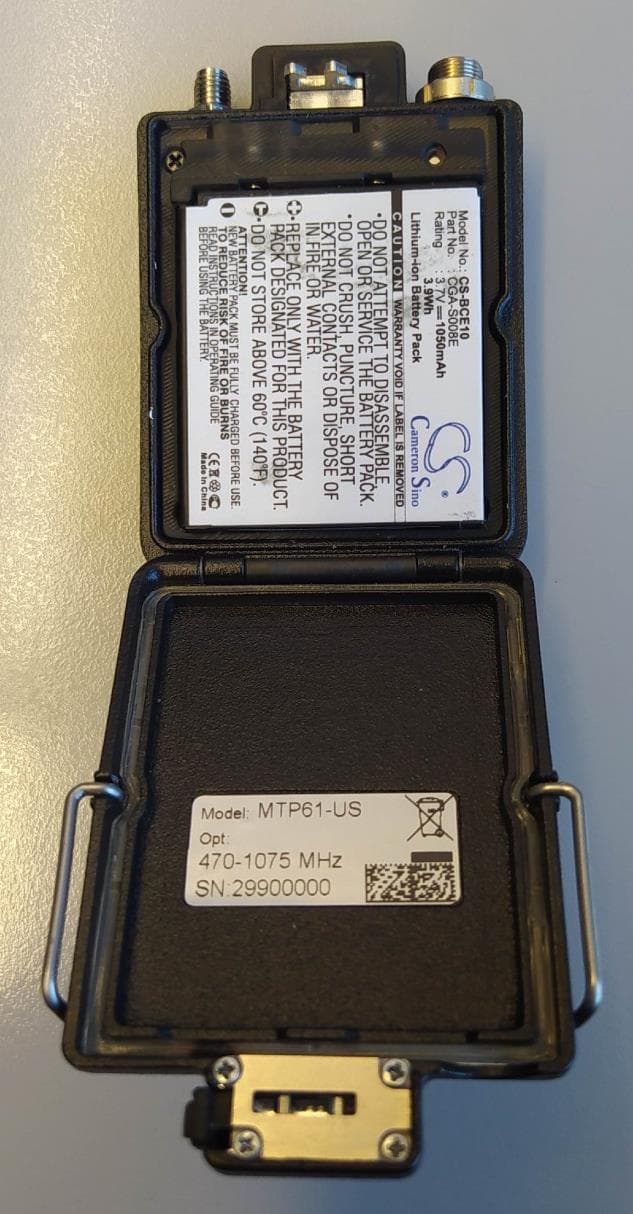
POUMTP61
Jul 23, 2023Wireless Microphone
Equipment Class
DWM - Part 15 Wireless Microphone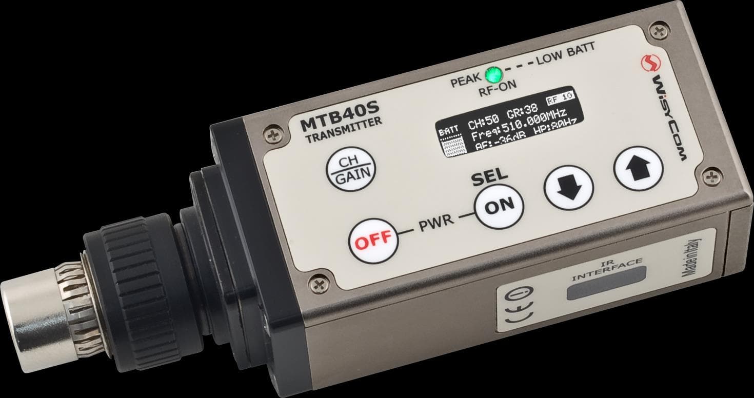
POUMTB40SUSX
Apr 20, 2015Plug on transmitter
Equipment Class
TBC - Licensed Broadcast Station Transmitter
POUMTK952N-0W2
Apr 11, 2015Dual Transmitter
Equipment Class
TNB - Licensed Non-Broadcast Station Transmitter
POUMTK952N-2W0
Apr 10, 2015Dual Transmitter
Equipment Class
TNB - Licensed Non-Broadcast Station Transmitter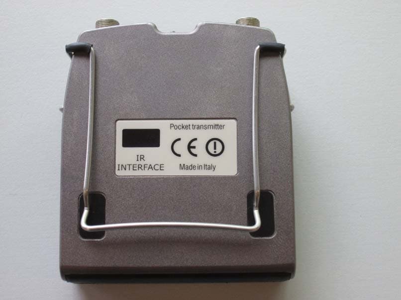
POUMTP40SUSX
Jul 01, 2014Wideband bodypack transmitter
Equipment Class
TBT - Licensed Broadcast Transmitter Worn on Body