POUMTP40Wideband bodypack transmitter
Wisycom s.r.l.
Click to zoom
Application Details
- Equipment Class
- TBT - Licensed Broadcast Transmitter Worn on Body
- Date of Grant
- Jun 17, 2013
- Application Purpose
- Original Equipment
- Date of Application
- Jun 12, 2013
- Equipment Note
- Wideband bodypack transmitter
- Frequency Range
- 614.25000000 - 697.92500000
- Company
- Wisycom s.r.l.
- Country
- Italy
Documents & Files
Document Text
Text extracted from the exhibit documents filed with the FCC. Open a document above to read the original.
Users Manual
MTP40 User Manual Wideband Wireless Professional Pocket Transmitter SN: ________________ Rev.02 (rif. FW 1.10.0L) Date: 12 June 2013 MTP40 E-series MTP40 User Manual Rev.02 2 Front LED color is the same of power switch. 2 3 5 6 4 INTRODUCTION “MTP40 is an extremely small and light pocket transmitter especially designed for professional wireless microphone applications” Very easy and quick to use thanks to OLED display, dedicated buttons and a joggle selector. MTP40 benefits also of the latest Wisycom RF technology along with an enhanced robustness against noise and inter-modulation. Fig. 1 ❶ Switch to enable wireless transmission, it also indicates the battery status and peak/mute operation (with PTT) ❷ In order to allow front visibility same colour information on (1) is replicated with this LED ❸ Oled display for transmitter setup ❹ <ch>, <gain> and 3 positions <selector> ❺ Battery holder ❻ Cover (to open push side buttons) 1. Fig. 2 Turn on wireless: Move the Wireless power switch in “I” position: switch becomes green (red indicate PTT/MUTE). A green blinking gives you indications on battery status. 1 Open MIC Body: Push the side buttons and flip down the cover, to access internal setup controls and batteries. Turn on display: Push <select switch> and hold it. MTP40 User Manual Rev.02 3 SAFETY INSTRUCTION Read this safety instruction and the manual first Follow all instructions and information. Do not lose this manual. Do not use this apparatus under the rain or near the water. Do not install the apparatus near heaters or in hot environments, do not use outside the operating temperature range. Do not open the apparatus, only qualified service technician are enabled to operate on it. The apparatus needs servicing when it is not properly working or is damaged by liquids, moisture or other objects are fallen in the apparatus. Use only accessories or replacement parts authorized or specified by the manufacturer. Clean the apparatus only with dry cloths, do not use liquids. Report the serial number and the purchasing date in front of the manual. It is needed to have proper replacement parts or accessories from the manufacturer. When replacement parts are needed, use only replacement parts authorized from the manufacturer. Substitution with not authorized parts could result in electric shock, hazards or fire. Keep attention on all the labels with warnings or hazards on the apparatus. LED INDICATIONS Led indication with bi-colour led (red & green) on wireless power switch (1) and in front led (2): - Wireless transmission status: green when RF transmission power is on. - Battery status: green steady, slowly blinking (< 25%), quickly blinking (<12%). - Modulation peek (if activated): red. - Ptt status: red if active (push to talk “pushed”). BATTERIES MTP40 is working with 2 AA alkaline or NiMH batteries (select correct type on setup controls). Battery status can be checked on internal OLED display or looking to LED status on power switch (see 1.1). BATTERY SUBSTITUTION Open transmitter cover and insert batteries following polarity indicated. Attention: always replace both the batteries MTP40 User Manual Rev.02 4 POWERING UP Move the wireless power switch (see Fig. 1) in “I” position to activate wireless transmission: a green LED lights up (blinking when battery is low!) SETUP CONTROL Open transmitter Body to access the “display and controls” area (Fig. 3): A. Graphics Display (OLED) B. Channel selection buttons (ch) C. MIC gain setup buttons (gain) D. 3 position selector (up / down / click) Fig. 3 OLED POWER UP (OLED IS IN OFF CONDITION) Pushing down selector (click), oled turns on. A first menu with serial NO and brand logo is displayed, then <status> menu enters automatically. Pushing and holding selector (click) > 2 sec, serial NO menu is displayed till (-/+) is selected. OLED POWER DOWN (OLED IS IN ON CONDITION) Pushing and holding selector (click) > 2 sec, display is turned off. Display turns off automatically after 15 sec, unless in <IRDA> menu or in <AUDIO> menu (with audio level < 5% from nominal). + - CLICK A B C D MTP40 User Manual Rev.02 5 + - CLICK DISPLAY MENU Setup menu are accessed in sequence: <STATUS> <PRESET> <TUNING> <AUDIO> <MIC> <RF POWER > <NOISE RED> <OTHER> <IRDA> <LOCK> Using <+/-> selector all menus can be accessed in sequence, push <click> to enter edit mode: <+/-> to setup field <click> again to confirm changes and exit. exit without confirmation if no button is pressed after a few seconds time out. <START UP> menu These menus are displayed during power up for few seconds. First one gives information of antenna to be used. The number displayed is the center-band of the antenna to be used. The second menu gives indication on product: - product id (MTP40), - a number which identify the working band 1 470-640 MHz 2 566-798 MHz 3 510-698 MHz - a number which identify the hardware version - the firmware release (110.0F), - the band in extended format and - the serial number. Keep selector pushed to hold this menu! <STATUS> menu This is the first menu displayed after power up. Major info are displayed: - Current channel/group (i.e. CH:00 GR:08) - Current frequency (i.e. 566.075 MHz) - Mic gain (i.e. AF: -04 dB) and high pass filter (i.e. HP:60 Hz) - “RF H” or “RF L” on top right if RF transmission is on at high or low power respectively - On bottom battery bar is displayed MTP40 User Manual Rev.02 6 <PRESET> menu This menu can be entered by scrolling selector, or pushing at the same time both quick channel setup buttons (<ch> & <gain>). MTP40 can recall configuration presets. “FACTORY” recall the Wisycom factory configuration. “USER” recall the user configuration (the transmitter configuration is copied into the USER using the “save to” submenu). All “USER” menus are not locked by default, thus this is quick way to unlock features! The other 8 configuration presets are user programmable thru the infrared and the PC interface (u…
Text truncated - open the document above for the full version.
Cover Letter(s)
W I SY C O M s .r .l. Via Spin, 156 I-36060 Romano d’Ezzelino (VI) Italy Tel. +39 0424 382605 Fax +39 0424 382733 www.wisycom.com e-mail: [email protected] FCC-ID: POUMTP40 FCC IDENTIFIER Wisycom S.R.L. grants the following rules: - the FCC identifier is placed in the battery compartment and the batteries installed don’t compromise the visibility of the FCC label - the user doesn’t required any special tools for access to the battery compartment - the FCC label isn’t placed on a removable part - the user manual reports clear information where find the FCC label WISYCOM S.R.L. Unipersonale Amministratore Unico Franco Maestrelli
Cover Letter(s)
CONFIDENTIALITY REQUEST Federal Communication Commission Equipment Authorization Division, Application Processing Branch 7435 Oakland Mills Road Columbia, MD 21048 October 15, 2012 TO WHOM IT MAY CONCERN Pursuant to Paragraphs §0.457 and 0.459 of the Commission’s Rules (47 C.F.R.) and Section §552(b)(4) of the Freedom of Information Act, Company requests confidentiality for the following products: FCC ID Number Product Title/Model: POUMTP40 MTP40 For the product stated above, we request that the following information be held confidential: 1. Circuit diagrams submitted as Equipment Authorization Electronic Filing attachment: "schematics”. 2. Block diagram submitted as Equipment Authorization Electronic Filing attachment: “block diagram”. 3. Operational description submitted as Equipment Authorization Electronic Filing attachment: “operational description” 4. Part list submitted as Equipment Authorization Electronic Filing attachment: “Part List” 5. Tuning procedure submitted as Equipment Authorization Electronic Filing attachment: “Tuning Procedure” The above exhibits contain Company trade secrets and proprietary information that could be of benefit to our competitors regarding the design of our mobile handset. This material is not customarily available to the general public and we request that it be withheld from public inspection. If you have any questions, please feel free to contact me at the address shown below. Sincerely, Name: Franco Maestrelli Company: Wisycom srl uninominale Address: via Spin, 156 36060 Romano d’Ezzelino-VI (Italy) Phone: +39 0424382605 Email: [email protected]
External Photos
Independent Testing Laboratory CMC Centro Misure Compatibilità S.r.l. Via dell’Elettronica, 12/C 36016 Thiene (VI) – ITALY Tel./Fax +39 0445 367702 www.cmclab.it - [email protected] Accredited by Ministry of Communications – Notified Body EMC Directive 2004/108/EC n° NB 2044 Page 1 of 1 EXTERNAL PHOTO
Internal Photos
Independent Testing Laboratory CMC Centro Misure Compatibilità S.r.l. Via dell’Elettronica, 12/C 36016 Thiene (VI) – ITALY Tel./Fax +39 0445 367702 www.cmclab.it - [email protected] Accredited by Ministry of Communications – Notified Body EMC Directive 2004/108/EC n° NB 2044 Page 1 of 2 INTERNAL PHOTO Independent Testing Laboratory CMC Centro Misure Compatibilità S.r.l. Via dell’Elettronica, 12/C 36016 Thiene (VI) – ITALY Tel./Fax +39 0445 367702 www.cmclab.it - [email protected] Accredited by Ministry of Communications – Notified Body EMC Directive 2004/108/EC n° NB 2044 Page 2 of 2
Test Report
Independent Testing Laboratory CMC Centro Misure Compatibilità S.r.l. Via dell’Elettronica, 12/C 36016 Thiene (VI) – ITALY Tel./Fax +39 0445 367702 www.cmclab.it - [email protected] Accredited by Ministry of Communications – Notified Body EMC Directive 2004/108/EC n° NB 2044 Test report R12157601 Rev. 1.0 Order M121576 page 1 of 58 TEST REPORT nr. R12157601 Federal Communication Commission (FCC) Test item Description .................... : Wideband bodypack transmitter Trademark ..................... : WISYCOM Model/Type ................... : MTP 40 Test Specification Standard ........................ : FCC Rules & Regulations, Title 47 - Part 74.861 (2011) Client’s name ............... : WISYCOM SRL Address ......................... : Via Spin,156 – 36060 Romano d'Ezzelino (VI) - Italy Manufacturer’s name . : Same ad client Address ......................... : Report Tested by ....................... : A. Bertezzolo - Technician Approved by .................. : R. Beghetto – Laboratory Manager Date of issue .................. : 11.06.13 Contents ........................ : 58 pages This test report shall not be reproduced except in full without the written approval of CMC. The test results presented in this report relate only to the item tested. CMC Centro Misure Compatibilità S.r.l. Via dell’Elettronica, 12/C 36016 Thiene (VI) Test report R12157601 Rev. 1.0 Order M121576 page 2 of 58 Index 1. SUMMARY ............................................................................................................................................................. 3 2. DESCRIPTION OF EQUIPMENT UNDER TEST (EUT) ................................................................................. 4 2.1 TEST SITE .............................................................................................................................................................. 4 3. TESTING AND SAMPLING ................................................................................................................................. 5 4. OPERATIVE CONDITIONS................................................................................................................................. 5 5. PHOTOGRAPH(S) OF EUT ................................................................................................................................. 6 6. EQUIPMENT LIST ................................................................................................................................................ 8 7. MEASUREMENT UNCERTAINTY .................................................................................................................... 9 8. REFERENCE DOCUMENTS ............................................................................................................................. 10 9. DEVIATION FROM TEST SPECIFICATION ................................................................................................. 11 10. TEST CASE VERDICTS...................................................................................................................................... 11 11. RESULTS............................................................................................................................................................... 11 11.1 PEAK OUTPUT POWER (CONDUCTED) ............................................................................................................. 12 11.2 FREQUENCY ERROR VS. VOLTAGE ................................................................................................................. 14 11.3 FREQUENCY ERROR VS. TEMPERATURE ......................................................................................................... 17 11.4 CHARACTERISTIC OF THE AUDIO MODULATION CIRCUITRY ........................................................................... 20 11.5 OCCUPIED BANDWIDTH .................................................................................................................................. 22 11.6 ATTENUATION POWER .................................................................................................................................... 23 11.7 RADIATED SPURIOUS (TRANSMITTER) ............................................................................................................ 24 12. GRAPHS AND TABLES ...................................................................................................................................... 28 CMC Centro Misure Compatibilità S.r.l. Via dell’Elettronica, 12/C 36016 Thiene (VI) Test report R12157601 Rev. 1.0 Order M121576 page 3 of 58 1. Summary Standard: FCC Rules & Regulations, Title 47 part 74 Test specifications Environmental Phenomena Tests sequence Result FCC – Title 47 Part 74.861 Peak Output Power 1 Complies FCC – Title 47 Part 74.861 Frequency Error vs. Voltage 2 Complies FCC – Title 47 Part 74.861 Frequency Error vs. Temperature 3 Complies FCC – Title 47 Part 74.861 Characteristic of the Audio Modulation 4 Complies FCC – Title 47 Part 74.861 Occupied Bandwidth 5 Complies FCC – Title 47 Part 74.861 Attenuation Power 6 Complies FCC – Title 47 Part 74.861 Radiated Spurious 7 Complies The Test Report was given to the Client representatives for necessary documentation of ratification of the tested equipment and it is valid for the FCC certification. CMC Centro Misure Compatibilità S.r.l. Via dell’Elettronica, 12/C 36016 Thiene (VI) Test report R12157601 Rev. 1.0 Order M121576 page 4 of 58 2. Description of Equipment under test (EUT) Power supply .......................................................................... : 3 Vdc from battery Type of equipment ............................................................... : Transmitter Unit Receiver Unit Fixed station Portable station Mobile station Alignment range ..................................................................... : 470 - 698 MHz Switching frequency .............................................…
Text truncated - open the document above for the full version.
Test Setup Photos
Independent Testing Laboratory CMC Centro Misure Compatibilità S.r.l. Via dell’Elettronica, 12/C 36016 Thiene (VI) – ITALY Tel./Fax +39 0445 367702 www.cmclab.it - [email protected] Accredited by Ministry of Communications – Notified Body EMC Directive 2004/108/EC n° NB 2044 Page 1 of 1 SETUP PHOTO
Contact Information
Applicant
Enzo Frigo(CTO)
Test Firm
CMC Centro Misure Compatibilit� srlBeghetto Renzo
Technical Specifications
| # | Rule Parts | Frequency Range | Power Output | Emission | Tolerance |
|---|---|---|---|---|---|
| 2 | 74.861 | 614.25 MHz - 697.925 MHz | 36.00 mW | 152KF3E | 0.62 ppm |
Other Applications from Wisycom s.r.l.
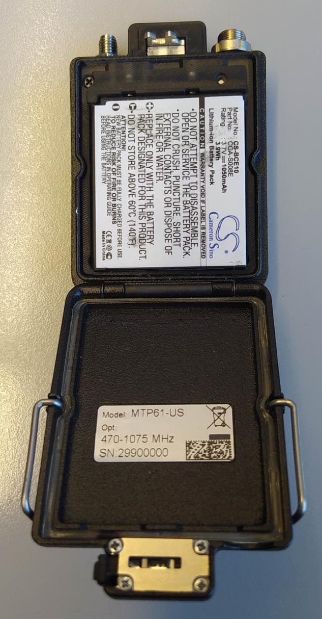
POUMTP61
Jul 23, 2023Wireless Microphone
Equipment Class
DWM - Part 15 Wireless Microphone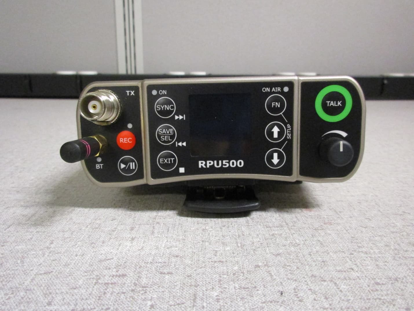
POURPU500
Sep 08, 2021Wireless Microphone
Equipment Class
DWM - Part 15 Wireless Microphone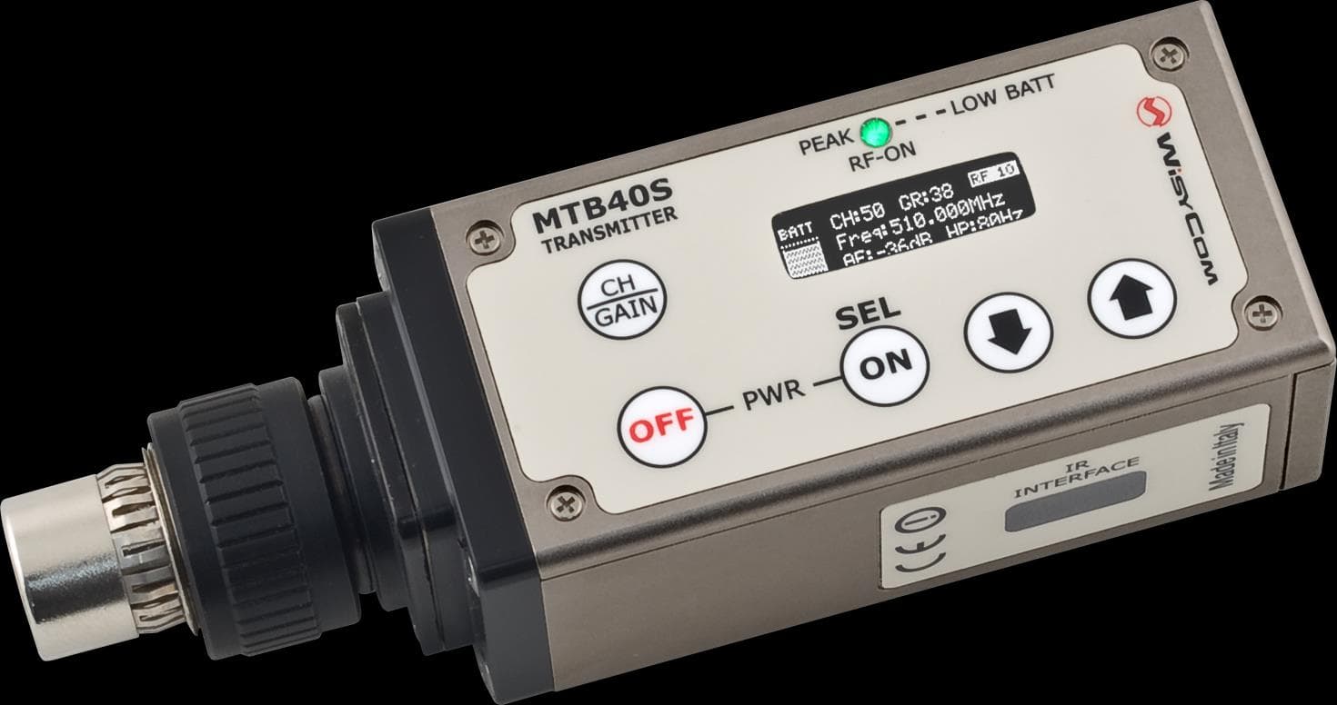
POUMTB40SUSX
Apr 20, 2015Plug on transmitter
Equipment Class
TBC - Licensed Broadcast Station Transmitter
POUMTK952N-0W2
Apr 11, 2015Dual Transmitter
Equipment Class
TNB - Licensed Non-Broadcast Station Transmitter
POUMTK952N-2W0
Apr 10, 2015Dual Transmitter
Equipment Class
TNB - Licensed Non-Broadcast Station Transmitter