PPD-AR5BCB-00022802.11a/b/g WIRELESS LAN CARDBUS CARD
Qualcomm Atheros, Inc.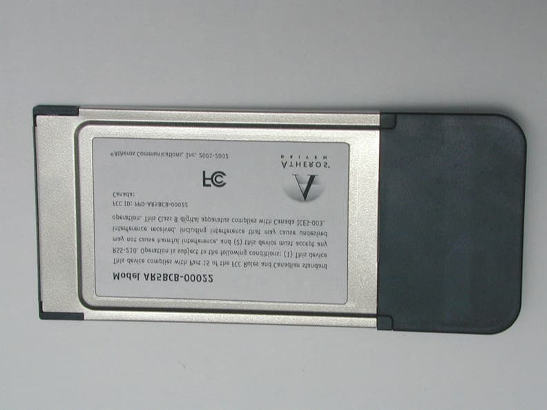
Click to zoom
Application Details
- Equipment Class
- NII - Unlicensed National Information Infrastructure TX
- Date of Grant
- Sep 10, 2002
- Application Purpose
- Original Equipment
- Date of Application
- Jul 11, 2002
- Equipment Note
- 802.11a/b/g WIRELESS LAN CARDBUS CARD
- Frequency Range
- 5180.00000000 - 5320.00000000
- Company
- Qualcomm Atheros, Inc.
- Country
- United States
Documents & Files
Document Text
Text extracted from the exhibit documents filed with the FCC. Open a document above to read the original.
Users Manual
AR5001 User Guide PRELIMINARY Revision July 2002 PRELIMINARY ii• AR5001 STA User’s GuideAtheros Communications, Inc. ii •July 2002COMPANY CONFIDENTIAL © 2000–2002 by Atheros Communications, Inc. All rights reserved. ATHEROS, the Atheros logo, 5-UP, Driving the Wireless Future, Atheros Driven, Atheros Turbo Mode, and the Air is Cleaner at 5-GHz are trademarks of Atheros Communications, Inc. All other trademarks are the property of their respective holders. Notice The information in this document has been carefully reviewed and is believed to be accurate. Nonetheless, this document is subject to change without notice, and Atheros Communications, Inc. (Atheros) assumes no responsibility for any inaccuracies that may be contained in this document, and makes no commitment to update or to keep current the contained information, or to notify a person or organization of any updates. Atheros reserves the right to make changes, at any time, in order to improve reliability, function or design and to attempt to supply the best product possible. Atheros does not represent that products described herein are free from patent infringement or from any other third party right. No part of this document may be reproduced, adapted or transmitted in any form or by any means, electronic or mechanical, for any purpose, except as expressly set forth in a written agreement signed by Atheros. Atheros or its affiliates may have patents or pending patent applications, trademarks, copyrights, maskwork rights or other intellectual property rights that apply to the ideas, material and information expressed herein. No license to such rights is provided except as expressly set forth in a written agreement signed by Atheros. ATHEROS MAKES NO WARRANTIES OF ANY KIND WITH REGARD TO THE CONTENT OF THIS DOCUMENT. IN NO EVENT SHALL ATHEROS BE LIABLE FOR DIRECT, INDIRECT, SPECIAL, INCIDENTAL SPECULATORY OR CONSEQUENTIAL DAMAGES ARISING FROM THE USE OR INABILITY TO USE THIS PRODUCT OR DOCUMENTATION, EVEN IF ADVISED OF THE POSSIBLITY OF SUCH DAMAGES. IN PARTICULAR, ATHEROS SHALL NOT HAVE LIABILITY FOR ANY HARDWARE, SOFTWARE, OR DATA TRANSMITTED OR OTHERWISE USED WITH THE PRODUCT, INCLUDING THE COSTS OF REPAIRING, REPLACING, INTEGRATING, INSTALLING OR RECOVERING SUCH HARDWARE, SOFTWARE OR DATA. ATHEROS SPECIFICALLY DISCLAIMS THE IMPLIED WARRANTIES OF MERCHANTIBILITY AND FITNESS FOR A PARTICULAR PURPOSE AS THEY MIGHT OTHERWISE APPLY TO THIS DOCUMENT AND TO THE IDEAS, MATERIAL AND INFORMATION EXPRESSED HEREIN. Document Number: 984-00016-003 PRELIMINARY Atheros Communications, Inc.•iii COMPANY CONFIDENTIALJuly 2002•iii Document Conventions Text Conventions Notices boldBold type within paragraph text indicates commands, file names, directory names, paths, output, or returned values. Example: The DK_Client package will not function unless you use the wdreg_install batchfile. italicWithin commands, italics indicate a variable that the user must specify. Example: mem_alloc size_in_bytes Titles of manuals or other published documents are also set in italics. Courier The Courier font indicates output or display. Example: Error:Unable to allocate memory for transfer! MenuThe Menu character tag is used for menu items. Example: Choose Edit > Copy. [ ]Within commands, items enclosed in square brackets are optional parameters or values that the user can choose to specify or omit. { }Within commands, items enclosed in braces are options from which the user must choose. |Within commands, the vertical bar separates options. ...An ellipsis indicates a repetition of the preceding parameter. >The right angle bracket separates successive menu selections. Example: Start > Programs > DK > wdreg_install. NOTE:This message denotes neutral or positive information that calls out important points to the text. A note provides information that may apply only in special cases. PRELIMINARY iv•AR5001 STA User’s GuideAtheros Communications, Inc. iv•July 2002COMPANY CONFIDENTIAL D O N O T C O P Y Revision History RevisionDescription of Changes June 2002Initial release. D O N O T C O P Y PRELIMINARY Atheros Communications, Inc.Contents•v COMPANY CONFIDENTIALJuly 2002•v Contents List of Figures . . . . . . . . . . . . . . . . . . . . . . . . . . . . . . . . vii List of Tables. . . . . . . . . . . . . . . . . . . . . . . . . . . . . . . . . ix Preface. . . . . . . . . . . . . . . . . . . . . . . . . . . . . . . . . . . . . . xi About this Document . . . . . . . . . . . . . . . . . . . . . . . . . . . . . . . xi Audience . . . . . . . . . . . . . . . . . . . . . . . . . . . . . . . . . . . . . . xii Additional Resources . . . . . . . . . . . . . . . . . . . . . . . . . . . . . . . xii 1Introduction . . . . . . . . . . . . . . . . . . . . . . . . . . . . . . . . . 1-1 Package Contents . . . . . . . . . . . . . . . . . . . . . . . . . . . . . . . . . 1-1 System Requirements . . . . . . . . . . . . . . . . . . . . . . . . . . . . . . . 1-2 2Windows 2000. . . . . . . . . . . . . . . . . . . . . . . . . . . . . . . . 2-1 Driver Installation (First-Time Install). . . . . . . . . . . . . . . . . . . . . . 2-1 Driver Installation (Previous Driver Installed) . . . . . . . . . . . . . . . . . 2-6 Driver Uninstallation . . . . . . . . . . . . . . . . . . . . . . . . . . . . . . 2-14 Device Configuration . . . . . . . . . . . . . . . . . . . . . . . . . . . . . . 2-17 Selecting Encryption Types. . . . . . . . . . . . . . . . . . . . . . . . . . . 2-23 Infrastructure Mode . . . . . . . . . . . . . . . . . . . . . . . . . . . . 2-26 Ad Hoc Mode . . . . . . . . . . . . . . . . . . . . . . . . . . . . . . . . 2-28 TCP/IP Setup . . . . . . . . . . . . . . . . . . . . . . . . . . . . . . . . 2-29 D O N O T C O P Y PRELIMINARY vi•AR5001 STA User’s GuideAtheros Communications, Inc. vi•July 2002COMPANY CONFIDENTIAL 3Windows 98 Second Edition . . . . . . . . . . . . . . . . . . . . 3-1 Driver Installation . . . . . . . . . . . . . . . . . . . . . . . . . . . . . . . . 3-1 Driver Uninst…
Text truncated - open the document above for the full version.
Cover Letter(s)
Atheros Communications, Inc. 529 Almanor Avenue Sunnyvale CA 94085 t 408 773 5200 f 408 773 9940 www.atheros.com Federal Communications Commission 7435 Oakland Mills Road Columbia, MD 21046 May 6th, 2002 Dear Examiner: I am writing to avoid the possibility of an inadvertent disclosure of proprietary information. The accompanying Form 731 is being filed with the commission on our behalf by a consulting and testing laborato ry. Included as exhibits with the enclosed application are block diagrams, schematics, and a detailed description of the theory of operation of the device. We ask that these portions (block diagrams, schematics, and theory of operation) of our application be withheld from public inspection as provided under FCC section 0.459. These documents contain details of the proprietary operation of product. These details are not readily discernible - even to technically sophisticated individuals - from our hardware and constitute trade secrets. We request therefore that these documents and this letter be segregated from the body of our evaluation report and withheld from public inspection. Thank you for your attention. Please let the undersigned know if the Commission disagrees with our position or requires further justification. Sincerely, Michael Green Manager of Global Product Compliance
Cover Letter(s)
Atheros Communications, Inc. 529 Almanor Avenue Sunnyvale CA 94085 t 408 773 5200 f 408 773 9940 www.atheros.com Federal Communications Commission 7435 Oakland Mills Road Columbia, MD 21046 May 6th, 2002 To Whom It May Concern: This letter authorizes Compliance Engineering Services, Inc as Agent for Atheros Communications, Inc., to sign applications before the Commission and to make representations to the FCC on our behalf. Compliance Engineering Services, Inc is to receive and exchange data between our company and the Commission. This authorization is made pursuant to Section 2.911(c) of the FCC Rules and expires on May 6 th , 2003. I hereby certify on behalf of Atheros Communications, Inc. located at 529 Almanor Ave, Sunnyvale, CA 94085 ("Applicant") that neither Applicant nor any party to the application (officers, directors, and 5% shareholders) is subject to a denial of Federal benefits that includes FCC benefits pursuant to section 5301 of the Anti-Drug Abuse Act of 1988. 21 U.S.C. 853a. Sincerely, Michael Green Manager of Global Product Compliance
Cover Letter(s)
From: Michael Robinson [[email protected]] Sent: Friday, August 30, 2002 9:49 AM To: Mike Kuo Subject: Re: Atheros CB22 FCC submission Hi Mike, It is clear that Professor Gandhi's average power of 21.3dBm from the 5GHz SAR report is higher than any of the average powers in the DTS/UNII reports. Note that the deltas between peak and average are higher for the "turbo" mode channels. This is due to the fact that the turbo spectrum has a wider 26dB bandwidth, which requires a wider video bandwidth setting on the spectrum analyzer, which in turn causes the peak power measurement to be higher. If you have any questions regarding this data, please let me know. Thanks for all of your help in this matter. -Mike Frequency (MHz) Peak Pwr Average Pwr UNII Report 5180 15.38 dBm 14 dBm 5260 19.51 dBm 18 dBm 5320 14.48 dBm 13.5 dBm 5210 16.29 dBm 14 dBm 5250 16.25 dBm 14 dBm 5290 17.89 dBm 15 dBm DTS Report 5745 19.13 dBm 18 dBm 5805 19.70 dBm 18 dBm 5825 19.23 dBm 18 dBm 5760 20.64 dBm 18 dBm 5800 21.99 dBm 18 dBm 2412 (11b) 18.22 dBm 18 dBm 2437 (11b) 17.57 dBm 18 dBm 2462 (11b) 17.47 dBm 18 dBm 2412 (11g) 19.22 dBm 18 dBm 2437 (11g) 19.77 dBm 18 dBm 2462 (11g) 18.86 dBm 18 dBm September 3, 2002 RESPONSES TO QUESTIONS ON THE SAR COMPLIANCE TESTING OF ATHEROS MODEL AR5BCB-00022 (FCC ID# PPD-AR5BCB-00022) CARDBUS CARD INSERTED INTO A LAPTOP COMPUTER 2. Supplement C contains information that can be adapted for system verification at frequencies outside of the P1528 0.3-3 GHz frequency range. Target values should be reported and can be established in the system or by numerical modeling. FCC public records include examples of lab-developed target values. If 5-GHz-band dipoles are not available, verification data using 2-4 GHz dipole and body liquid may be accepted in the interim. Response: As given in Appendix A [a] of the SAR Test Report, a half-wave dipole at 1900 MHz (λ/2 = 78.95 mm) was used for system verification. A dipole at 1900 MHz was used in the absence of dipoles at 2450 MHz or for the frequency band 5.18-5.825 GHz. This dipole of length 76.0 mm and diameter 1.5 mm and h = 39.5 mm is shown in Fig. a. The measured SAR distributions for variable spacings of 10, 15, 20, and 25 mm of the dipole for a flat phantom and spacings of 5, 15, and 25 mm of the dipole for a sphere phantom are given in Figs. 5 and 7 of Appendix A. Also given in the same figures are the SAR values calculated using the FDTD numerical method. The agreement of the measured SAR distributions with those obtained numerically using the FDTD method is very good. Taken from Tables IV and V of Appendix A, the difference between measured and calculated peak 1-g SARs are less than ± 5 percent at 1900 MHz. 3. Supplement C contains evaluation guidelines for mobile and portable devices, not just handheld cellular telephones. Supplement C Appendix B II 7c states, "description, illustration and SAR distribution plots showing the peak SAR locations with respect to the phantom and the test device." Response: An illustration (top view) showing the peak SAR location with respect to the phantom and the Atheros Model AR5BCB CardBus Card for the laptop computer pressed against the bottom of the planar tissue-simulant phantom is attached here as Fig. b. As stated in Section IV of the SAR Test Report, the highest SARs were measured for the region of the phantom above the PC card. The highest peak 1-g SAR was measured for the region above the radiating antenna as shown in Fig. b. This region was measured with a stepper-motor-controlled step size of 2 mm along the three orthogonal axes to obtain peak 1-g SAR. The SAR distributions measured with a step size of 2 mm have been given in Tables 1-4 (of the SAR Test Report) for frequencies of 5.18, 5.32, 5.745, and 5.825 GHz, respectively. An illustration showing the peak 1-g SAR location for the End-on placement (with the card edge at 90 and separated from the bottom of the phantom by 2.5 cm) is given in Fig. c. The detailed SAR distributions measured with a step size of 2 mm are given in Tables 5-8 of the SAR Test Report for frequencies of 5.18, 5.32, 5.745, and 5.825 GHz, respectively. 2 4. Please submit SAR liquid recipes and mixing details. Response: On page 2 of the SAR Test Report, we give the composition of the tissue-simulant fluid used for present measurements. This composition developed at the University of Utah consists of 68.0% water, 31.0% sugar, and 1% HEC. The measured and pre-weighed amount of water is mixed slowly with the pre-weighed amount of sugar (310 g for each kg of the final fluid) while stirring the water in. The 1% HEC is added into the thick syrupy fluid at the end and mixed in. Because of micro bubbles that result, the fluid is allowed to stand for a period of 3-7 days until it is cleared of the air bubbles and is transparent at that stage. 5. Please submit SAR liquid parameter test details and data analysis. Response: As given on page 2 of the SAR Test Report, the Hewlett Packard Model HP85070B Dielectric Probe (rated frequency band 200 MHz to 20 GHz) in conjunction with HP Model 8720C Network Analyzer (50 MHz-20 GHz) is used for measurement of the dielectric properties of the tissue-simulant fluid given in item 4. This commercial probe (see Fig. d) is an open-circuited transmission-line (coaxial line) probe described in Section B.1.2 of the Draft IEEE Standard 1528 [b]. The theory of the open- circuited coaxial line method has been described in scientific literature [c, d, e]. We have previously used this method in determining the dielectric properties of tissue-simulant materials at 6 GHz [f]. In this method, the complex reflection coefficient Γ ∗ measured for the open end of the coaxial line can be used to calculate the complex permittivity ε ∗ from the following equation [f] ε ∗ = 1−Γ ∗ jωZ o C o 1+Γ ∗ () − C f C o (1) where Z o is the characteristic impedance (50 Ω) for the coaxial line, C o is the capacitance when the line is in air and C f is the capacitance that acc…
Text truncated - open the document above for the full version.
ID Label/Location Info
This device complies with Part 15 of the FCC Rules and Canadian standard RSS-210. Operation is subject to the following conditions: (1) This device may not cause harmful interference, and (2) this device must accept any interference received, including interference that may cause undesired operation. This Class B digital apparatus complies with Canada ICES-003. ©Atheros Communications, Inc. 2001-2002 FCC ID: PPD-AR5BCB-00022 Model AR5BCB-00022 Canada:
Operational Description
Technical Description FCC ID: PPD-AR5BCB-00022 The Atheros AR5BCB-00022 is a high performance 802.11a/b/g WLAN client product intended for laptop applications. It operates in the 5.15-5.35 GHz, 5.725 - 5.850GHz, and 2.412-2.484GHz bands with a maximum Tx output power of 136mW. The product uses two symmetric integral antennas for diversity operation. Each has a 1dBi gain. The AR5BCB-00022 design is based on an Atheros AR5001X three-chip solution. The three chips include: AR5211: Multiprotocol MAC/baseband processor, and CardBus/PCI bus interface. AR5111 Radio-on-a-Chip (RoC): An all-CMOS single-chip radio transceiver that includes a power amplifier, and integrated dual conversion filters to convert signals from 5 GHz to the baseband range for use by the AR5211. The AR5111 offers fully integrated transmitter, receiver, and frequency synthesizer functions; eliminating the need for external voltage controlled oscillators (VCOs) and surface acoustic wave (SAW) filters. AR2111 Radio-on-a-Chip (RoC): An all-CMOS radio transceiver that, when combined with the AR5111, implements a 2.4GHz 802.11b/g radio solution. The AR2111 offers fully integrated transmitter, receiver, and frequency synthesizer functions. Like the AR5111, the AR2111 does not require external VCO’s or SAW filters.
Parts List/Tune Up Info
Document Number: 255-01116-050 AR5BCB-00022 CardBus Revision 050 Reference Design Bill of Materials Item QuantityReferencePart DescriptionVendor Part NumberVendor Alternate Vendor Part Number Alternate Vendor 11C9015pF,0402,NPO,+/-0.25pF,50V0402CG150C9BPhycomp 21C896.8pF,0402,NPO,+/-0.25pF,50V0402CG689C9BPhycomp 327 C12,C13,C97,C102,C105,C106,C108,C1 10,C111,C113,C114,C115,C116,C118,C 119,C152,C155,C182,C190,C193,C321, C324,C328,C346,C347,C348,C349 10pF,0402,NPO,+/-5%,50V0402CG100J9BPhycomp 47C55,C56,C87,C156,C173,C178,C18022pF,0402,NPO,+/-5%,50V0402CG220J9BPhycomp 53C26,C92,C1578.2pF,0402,NPO,+/-0.25pF,50V0402CG829C9BPhycomp 611 C14,C19,C37,C128,C145,C146,C147,C1 49,C150,C151,C327 0.01uF,0402,X7R,+/-10%16V04022R103K7BPhycomp 75C15,C17,C21,C23,C1924.7uF,1206,Y5V,+80/-20%,10V12062F475Z6BPhycomp 814 C16,C52,C58,C91,C93,C121,C122,C126 ,C132,C135,C138,C148,C186,C188 0.1uF,0402,Y5V,+80/-20%,16V04022F104Z7BPhycomp 91C1391.8pF,0402,NPO,+/-0.25pF,50V0402CG189C9B 106C69,C70,C72,C78,C109,C191120pF,0402,NPO,5%,50V0402CG121J9BPhycomp 111C2022uF,1210,Y5V,+80/-20%,10VGJ232NF51A226ZD01Murata 123C22,C24,C422.2uF,0805, Y5V,+80/-20%,16V08052F225Z7BPhycomp 1320 C33,C35,C36,C40,C44,C48,C51,C53,C6 3,C84,C85,C100,C166,C167,C177,C326 ,C331,C340,C350,C351 1pF,0402,NPO,+/-0.25pF,50V0402CG109C9BPhycomp 142C11,C341uF,0603,X5R,+/-10%,10VGRM188R61A105KMurata 152C45,C4630pF,0603,1%,50VGRM1885C1H300FD01Murata 1610 C43,C49,C54,C57,C64,C103,C176,C179 ,C325,C345 330pF,0402,X7R,+/-5%,50V04022R331J9BPhycomp 175C30,C31,C74,C77,C3300.5pF,0402,NPO,+/-0.25pF,50VECJ-0EC1H0R5CPanasonic 184C322,C329,C336,C3371.5pF,0402,NPO,+/-0.25pF,50V0402CG159C9BPhycomp 1925 C1,C2,C3,C4,C5,C6,C7,C8,C71,C73,C7 9,C81,C94,C96,C153,C161,C163,C171, C339,C343,C344,C352,C353,C354,C35 5 2.2pF,0402,NPO,+/-0.25pF,50V0402CG229C9BPhycomp 201C65470pF,0402,X7R,+/-10%,50V 04022R471K9B Phycomp 212C18,C8610uF,1206,Y5V,+80/-20%,10V 12062F106Z6B Phycomp 222D1,D4Single Schottky diodeSMS7630-996Alpha Industries 233D5,D6,D7Anti-parallel PIN diodeHMPP-3892-BLKAgilent Technologies 242DS3,DS4LED,0603LTST-C190GKTLiteon 251 F1Balun, 5.150GHz-5.875GHz, 50Ohm/100Ohm 5512BL15B100Johanson TechnologyLDB215G5110C-001Murata 261F35GHz band pass filterLFB215G51SG8A132Murata 271F65GHz band pass filterTDFS8A-5437Z-10AToko 281F82.4GHz band pass filterMDR747FSoshin 291F92.4GHz band pass filterMDR746FSoshin 301F102.4GHz BalunHHM-1517TDK 312J1,J2Antenna, CB, WidebandTBDAtheros 321J3CardBus connectorNVS-CN-CB10.21TRNovus Technology 331L14.7uH078-472LK-000Coilcraft 341L91.5nH,0402,+/-0.1nHLQP15MN1N5B02BMurata 352L17,L182.2nH,0402,+/-0.1nHLQP15MN2N2B00Murata 362L45,L462.7nH,0402,+/-0.1nHLQP15MN2N7B00Murata 371L73.3nH,0402,+/-0.1nHLQP15MN3N3B00Murata 381L103.9nH,0402,+/-0.1nHLQP15MN3N9B00Murata 393L4,L42,L43Ferrite bead,0805,0.8Ohm maxBK 2125LM252-TTaiyo Yuden 407L20,L22,L24,L25,L26,L47,L4818nH,0402,+/-5%LQG15HN18NJ02BMurata 412L19,L2810nH,0402,+/-5%LQG15HN10NJ02BMurata 424L2,L3,L5,L61uH,0603,5%078-102LJ-000Coilcraft 431L401uH, 1008ELJ-PC1R0MFPanasonic 446L8,L11,L23,L31,L32,L336.8nH,0402,+/-5%LQG15HN6N8J02BMurata 451L214.7nH,0402,+/-0.1nHLQP15MN4N7B00Murata 463Q1,Q7,Q92N3906, SOT-323, PNPMMST3906Diodes, Inc.CMPT3906Rohm 472Q3,Q62N3904, SOT-323, NPNMMST3904Diodes, Inc.CMPT3904Rohm 481Q42N7002, N Channel, SOT232N7002Fairchild 491Q55GHz low noise amplifierATF-551M4-BLKAgilent Technologies 501Q82.4GHz low noise amplifierSGA-8343Sirenza 511R1020k,0402,5%,1/16WCR10B203JTRG AllenRM73B1E203J KOA 523R12,R69,R1036.19k,0402,1%,1/16WCR10A6191FTRG Allen RK73H1E6191F KOA 531R20100k, 0402,1%, 1/16WCR10A1003FTRG AllenRK73H1E1003FKOA 545R14,R21,R131,R132,R145365,0402,1%,1/16WCR10A3650FTRG Allen RK73H1E3650F KOA 551R2324k,0402,1%,1/16WCR10A3243FTRG Allen RK73H1E3243F KOA 5611 R36,R38,R48,R49,R62,R63,R67,R152,R 153,R156,R157 221,0402,1%,1/16WCR10A2210FTRG AllenRK73H1E2210FKOA 5710 R1,R11,R27,R45,R78,R133,R134,R160, L15,L16 0,0402,5%,1/16WERJ-2GE0R00XPanasonic 581L440,1206,5%,1/8WERJ-8GEY0R00VPanasonic 5912 R24,R28,R40,R46,R73,R77,R136,R137, R139,R154,R155,R159 10k,0402,1%,1/16WCR10A1002FTRG AllenRK73H1E1002FKOA 601R2939,0402,5%,1/16W9C04021A39R9JLHF3Phycomp/YageoMCR01MZSJ390Rohm 611R16133,0402,5%,1/16WCR10B330JTRG Allen RM73B1E330J KOA 621R3309k,0402,1%,1/16WCR10A3093FTRG Allen RK73H1E3093F KOA 632R15,R165511,0402,1%,1/16WCR10A5110FTRG Allen RK73H1E5110F KOA 643R16,R25,R3915,0402,1%,1/16WCR10A15R0FTRG Allen RK73H1E15R0F KOA 651R42.2,0402,1%,1/16WMCR01MZSF2R2RohmERJ2RBF2R200VPanasonic 662R26,R413.57k,0402,1%,1/16WCR10A3571FTRG AllenRK73H1E3571FKOA 672R30,R471.1k,0402,1%,1/16WCR10A1101FTRG Allen RK73H1E1101F KOA 681R1465.1k,0402,5%CR10B512JTRG AllenRM73B1E512JKOA 693 R18,R35,R76 47,0402,5%1/16WCR10B470JTRG Allen RM73B1E470J KOA Atheros Communications, Inc. All rights reserved Copyright 2002 Company Confidential Subject to Change Without Notice AR5001X CardBus-050 BOM Page 1 of 2 Document Number: 255-01116-050 AR5BCB-00022 CardBus Revision 050 Reference Design Bill of Materials Item QuantityReferencePart DescriptionVendor Part NumberVendor Alternate Vendor Part Number Alternate Vendor 702R162,R163150,04021%,1/16WCR10A1500FTRG AllenRK73H1E1500FKOA 711R164390,0402,5%,1/16WRM73B1E391JKOA 721R15143k,0402,5%,1/16WCR10B433JTRG Allen RM73B1E433J KOA 731R79100,0402,5%,1/16W CR10B101JT RG AllenRM73B1E101JKOA 741R1471M,0402,5%,1/16WCR10B105JTRG Allen RM73B1E105J KOA 751R33432,0402,1%,1/16WCR10A4320FTRG AllenRK73H1E4320FKOA 762R1581k,0402,5%1/16WCR10B102JTRG AllenRM73B1E102JKOA 771R43200,0402,5%, 1/16WCR10B201JTRG AllenRM73B1E201J KOA 781S1SPDT RF SwitchAC812Alpha Industries 791S3In-line switchMM8430-2600TB1Murata 801U1AR2111AR2111Atheros 811U2600mA switching regulator,QLP16VT102Q-ADJVolterra 821 U4802.11a RoC - radio on a chip, 64- lead leadless package AR5111Atheros 831U32.5V LDO,SOT25TK71725SCLToko 841U55GHz power amplifierLX5503Microsemi 851 U6802.11a MAC and baseband, BGA196 AR5211Atheros 861U92.4GHz power amplifierRFSP2010RF Solutions 871U22EEPROM,16K,TSSOP8AT93C86-10TI-2.7Atmel 881U23DPDT RF SwitchMASWSS0039M/A-COM…
Text truncated - open the document above for the full version.
RF Exposure Info
SAR COMPLIANCE TESTING OF ATHEROS COMMUNICATIONS MODEL AR5BCB- 00022 (FCC ID# PPD-AR5BCB-00022) CARDBUS CARD INSERTED INTO A LAPTOP COMPUTER July 3, 2002 Submitted to: Mr. Jason Zheng Atheros Communications 529 Almanor Avenue Sunnyvale, CA 94085-3512 Submitted by: Om P. Gandhi Professor of Electrical and Computer Engineering University of Utah 50 S Central Campus Dr., Rm. 3280 Salt Lake City, UT 84112-9206 2 SAR COMPLIANCE TESTING OF ATHEROS COMMUNICATIONS MODEL AR5BCB- 00022 (FCC ID# PPD-AR5BCB-00022) CARDBUS CARD INSERTED INTO A LAPTOP COMPUTER I. Introduction The U.S. Federal Communications Commission (FCC) has adopted limits of human exposure to RF emissions from mobile and portable devices that are regulated by the FCC [1]. The FCC has also issued Supplement C (Edition 97-01) to OET Bulletin 65 [2] and a more recent version of the same [3] defining both the measurement and the computational procedures that should be followed for evaluating compliance of mobile and portable devices with FCC limits for human exposure to radiofrequency emissions. We have used the measurement procedure for SAR compliance testing of the Atheros Communications CardBus Card (FCC ID: PPD-AR5BCB-00022) inserted into a laptop computer. A photograph of the unit with the CardBus Card inserted into the laptop computer is given in Fig. 1. A picture of the Model AR5BCB-00022 CardBus Card placed on the laptop is given in Fig. 2. The Atheros Model AR5BCB-00022 CardBus Card operates with a nominal conducted RF power output of 21.3 dBm (136 mW) for the frequency band 5.18-5.825 GHz. For SAR measurements, two configurations of the wireless PC relative to the experimental phantom have been used: a. Since the wireless PC may possibly be placed on a user's lap where the RF antennas would be the closest to the body, a planar phantom model with inside dimensions 12" × 16.5" (30.5 × 41.9 cm) and a base thickness of 2.0 ± 0.2 mm (recommended in [3]) was used for SAR measurements and the wireless PC cards mounted in a portable computer (as in Fig. 1) pressed against the bottom of this phantom (see Fig. 3). b. For a bystander, the "end-on" SAR value is obtained for the PC and the card edge at 90° to the flat phantom with a spacing of 2.5 cm (see Fig. 4). 2 II. Experimental Measurements of SAR Distribution As aforementioned, the measurements of the SAR distributions for the Atheros Model AR5BCB-00022 CardBus Card inserted into a laptop computer (as in Fig. 1), both for the "above-lap" and "end-on" positions, were done with a planar rectangular box phantom made of acrylic of inside dimensions 12" × 16.5" (30.5 × 41.9 cm) shown in Figs. 3 and 4 for "above-lap" and "end-on" positions, respectively. This box phantom of external dimensions 13" × 17.5" (33 × 44.5 cm) is filled with a tissue-simulant fluid up to a depth of 15 cm. As recommended in [3], the base thickness of the box phantom is 2.0 ± 0.2 mm (0.079"). As seen in Figs. 3 and 4, a 1" thick Styrofoam block is used under the base, except for the region of the wireless laptop to prevent bending of the 2 mm thin base. Also for the SAR testing for the "end-on" position, a separation of 1" (2.5 cm) from the end of the PC card to the bottom of the planar phantom is used. The tissue-simulant fluid uses a composition developed at the University of Utah which consists of 68.0% water, 31.0% sugar and 1% HEC. For this composition, we have measured the dielectric properties using a Hewlett Packard (HP) Model 85070B Dielectric Probe in conjunction with HP Model 8720C Network Analyzer (50 MHz-20 GHz). The measured dielectric properties at a mid band frequency of 5.30 GHz are as follows: ε r = 48.5 ± 1.7 and σ = 5.40 ± 0.08 S/m. From the FCC Supplement C [3], we obtain the desired dielectric properties to simulate the body tissue at the midband frequency of 5.30 GHz to be ε r = 48.9 and σ = 5.42 S/m. Thus, the measured properties for the body-simulant fluid are close to the desired values. III. Calibration of the E-Field Probe Supplement C, Appendix D does not spell out a detailed procedure to use for system verification and electric field calibration for frequencies above 3000 MHz. However, the IEEE Draft Standard P1528 [4] does suggest a recommended procedure for probe calibration (see Section 4.4.1 of [4]) for frequencies above 800 MHz where waveguide size is manageable. Calibration using a rectangular waveguide is recommended. As in some previously reported 3 SAR measurements at 6 GHz [5], we have calibrated the Narda Model 8021 Miniature Broadband Electric Field Probe of tip diameter 4 mm (internal dipole dimensions on the order of 2.5 mm) using a rectangular waveguide WR 159 (of internal dimensions 1.590 × 0.795 inches) that was filled with the tissue-simulant fluid of composition given in Section II. The triaxial (3 dipole) E-field probe was originally developed by Howard Bassen and colleagues of FDA and has been manufactured under license by Narda Microwave Corporation, Hauppage, New York. The probe is described in detail in references 6 and 7. It uses three orthogonal pick up dipoles each of length about 2.5 mm with their own leadless zero voltage Schottky barrier diodes operating in the square law region. The sum of the three diode outputs read by three microvoltmeters [8] gives an output proportional to E 2 . As suggested in the Draft Standard P1526, the waveguide (WR 159) filled with the tissue-simulant fluid was maintained vertically. From microwave field theory [see e.g. ref. 9], the transverse field distribution in the liquid corresponds to the fundamental mode (TE 10 ) with an exponential decay in the vertical direction (z-axis). The liquid level was 15 cm deep which is deep enough to guarantee that reflections from the top liquid surface do not affect the calibration. By comparing the square of the decaying electric fields expected in the tissue from the analytical expressions for the TE 10 mode of the rectangular waveguide, we obtained a calibration factor of 2.99 (mW/kg)…
Text truncated - open the document above for the full version.
Test Report
FCC CFR47 PART 15 SUBPART E CERTIFICATION TEST REPORT FOR ATHEROS COMMUNICATIONS, INC. 802.11a/b/g WIRELESS LAN CARDBUS CARD MODEL NUMBER: AR5BCB-00022 BRAND NAME: ATHEROS FCC ID: PPD-AR5BCB-00022 REPORT NUMBER: 02U1380 ISSUE DATE: JULY 11, 2002 Prepared for ATHEROS COMMUNICATIONS, INC. 529 ALMANOR AVENUE SUNNYVALE, CA 94085-3512 USA Prepared by COMPLIANCE CERTIFICATION SERVICES 561F MONTEREY ROAD, MORGAN HILL, CA 95037, USA TEL: (408) 463-0885 FAX: (408) 463-0888 REPORT NO: 02U1380-1 DATE: JULY 11, 2002 EUT: 802.11a WIRELESS LAN CARDBUS CARD FCC ID: PPD-AR5BCB-00022 Page 2 of 80 COMPLIANCE CERTIFICATION SERVICES DOCUMENT NO: CCSUP4031A 561F MONTEREY ROAD, MORGAN HILL, CA 95037 USA TEL: (408) 463-0885 FAX: (408) 463-0888 This report shall not be reproduced except in full, without the written approval of CCS. This document may be altered or revised by Compliance Certification Services personnel only, and shall be noted in the revision section of the document. TABLE OF CONTENTS 1. TEST RESULT CERTIFICATION.................................................................................................3 2. EUT DESCRIPTION.........................................................................................................................4 3. TEST METHODOLOGY..................................................................................................................5 4. FACILITIES AND ACCREDITATION..........................................................................................5 4.1. FACILITIES AND EQUIPMENT.................................................................................................5 4.2. LABORATORY ACCREDITATIONS AND LISTINGS.................................................................5 4.3. TABLE OF ACCREDITATIONS AND LISTINGS....................................................................…
Text truncated - open the document above for the full version.
Contact Information
Applicant
Paul Guckian(Vice President, Regulatory Engineering)
Technical Contact
COMPLIANCE CERTIFICATION SERVICESSTEVE CHENG
408-463-0885
561 F MONTEREY ROAD · MORGAN HILL, California · United States
Non-Technical Contact
COMPLIANCE CERTIFICATION SERVICESCHRISTINE VU
[email protected]408-463-0885
Test Firm
Compliance Certification Services IncSteve Cheng
Technical Specifications
| # | Rule Parts | Frequency Range | Power Output |
|---|---|---|---|
| 1 | 15E | 5.18 GHz - 5.32 GHz | 90.00 mW |
Other Applications from Qualcomm Atheros, Inc.
PPD-QCNFA425
Sep 01, 2015Single Stream 802.11a/b/g/n/ac + BT 4.1 M.2 1216 Type Card
Equipment Class
DTS - Digital Transmission System
PPD-QCA9008-SBD1
Aug 18, 2015802.11ad MODULE
Equipment Class
DXT - Part 15 Low Power Transceiver, Rx Verified
PPD-QCNFA344AH
May 27, 2015802.11a/b/g/n/ac + BT 4.1 M.2 2230 Type Card
Equipment Class
JBP - Part 15 Class B Computing Device Peripheral
PPD-QCNFA364AH
May 27, 2015802.11a/b/g/n/ac + BT 4.1 M.2 2230 Type Card
Equipment Class
DTS - Digital Transmission System
PPD-QCNFA344A
Apr 30, 2015802.11a/b/g/n/ac + BT 4.1 M.2 2230 Type Card
Equipment Class
NII - Unlicensed National Information Infrastructure TX