PPD-AR5BCB-00032802.11 a/b/g Cardbus
Qualcomm Atheros, Inc.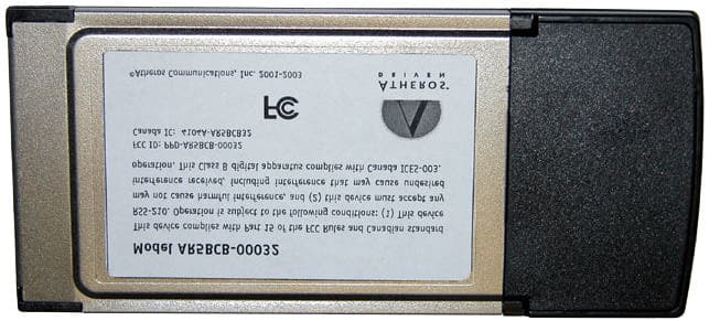
Click to zoom
Application Details
- Equipment Class
- NII - Unlicensed National Information Infrastructure TX
- Date of Grant
- Aug 21, 2003
- Application Purpose
- Original Equipment
- Date of Application
- May 28, 2003
- Equipment Note
- 802.11 a/b/g Cardbus
- Frequency Range
- 5180.00000000 - 5320.00000000
- Company
- Qualcomm Atheros, Inc.
- Country
- United States
Documents & Files
Document Text
Text extracted from the exhibit documents filed with the FCC. Open a document above to read the original.
Users Manual
AR5BCB-00032 Cardbus Card User’s Guide Revision February 2003 ii• Cardbus Card User’s GuideAtheros Communications, Inc. ii •February 2003COMPANY CONFIDENTIAL © 2000–2003 by Atheros Communications, Inc. All rights reserved. ATH ER OS, 5-UP, Driving the Wireless Future, Atheros Driven, Atheros Turbo Mode, and the Air is Cleaner at 5-GHz are trademarks of Atheros Communications, Inc. The Atheros logo is a registered trademark of Atheros Communications, Inc. All other trademarks are the property of their respective holders. Subject to change without notice. Notice The information in this document has been carefully reviewed and is believed to be accurate. Nonetheless, this document is subject to change without notice, and Atheros Communications, Inc. (Atheros) assumes no responsibility for any inaccuracies that may be contained in this document, and makes no commitment to update or to keep current the contained information, or to notify a person or organization of any updates. Atheros reserves the right to make changes, at any time, in order to improve reliability, function or design and to attempt to supply the best product possible. Atheros does not represent that products described herein are free from patent infringement or from any other third party right. No part of this document may be reproduced, adapted or transmitted in any form or by any means, electronic or mechanical, for any purpose, except as expressly set forth in a written agreement signed by Atheros. Atheros or its affiliates may have patents or pending patent applications, trademarks, copyrights, maskwork rights or other intellectual property rights that apply to the ideas, material and information expressed herein. No license to such rights is provided except as expressly set forth in a written agreement signed by Atheros. ATHEROS MAKES NO WARRANTIES OF ANY KIND WITH REGARD TO THE CONTENT OF THIS DOCUMENT. IN NO EVENT SHALL ATHEROS BE LIABLE FOR DIRECT, INDIRECT, SPECIAL, INCIDENTAL SPECULATORY OR CONSEQUENTIAL DAMAGES ARISING FROM THE USE OR INABILITY TO USE THIS PRODUCT OR DOCUMENTATION, EVEN IF ADVISED OF THE POSSIBLITY OF SUCH DAMAGES. IN PARTICULAR, ATHEROS SHALL NOT HAVE LIABILITY FOR ANY HARDWARE, SOFTWARE, OR DATA TRANSMITTED OR OTHERWISE USED WITH THE PRODUCT, INCLUDING THE COSTS OF REPAIRING, REPLACING, INTEGRATING, INSTALLING OR RECOVERING SUCH HARDWARE, SOFTWARE OR DATA. ATHEROS SPECIFICALLY DISCLAIMS THE IMPLIED WARRANTIES OF MERCHANTIBILITY AND FITNESS FOR A PARTICULAR PURPOSE AS THEY MIGHT OTHERWISE APPLY TO THIS DOCUMENT AND TO THE IDEAS, MATERIAL AND INFORMATION EXPRESSED HEREIN. Document Number: 984-00016-005 Atheros Communications, Inc.•iii COMPANY CONFIDENTIALFebruary 2003•iii Document Conventions Text Conventions Notices boldBold type within paragraph text indicates commands, file names, directory names, paths, output, or returned values. Example: The DK_Client package will not function, except when the wdreg_install batchfile is used. italicWithin commands, italics indicate a variable that the user must specify. Example: mem_alloc size_in_bytes Titles of manuals or other published documents are also set in italics. Courier The Courier font indicates output or display. Example: Error:Unable to allocate memory for transfer! [ ]Within commands, items enclosed in square brackets are optional parameters or values that the user can choose to specify or omit. { }Within commands, items enclosed in braces are options from which the user must choose. |Within commands, the vertical bar separates options. ...An ellipsis indicates a repetition of the preceding parameter. >The right angle bracket separates successive menu selections. Example: Start > Programs > DK > wdreg_install. NOTE:This message denotes neutral or positive information that calls out important points to the text. A note provides information that may apply only in special cases. iv• Cardbus Card User’s GuideAtheros Communications, Inc. iv •February 2003COMPANY CONFIDENTIAL D O N O T C O P Y D O N O T C O P Y Atheros Communications, Inc.Contents •v COMPANY CONFIDENTIALFebruary 2003•v Contents List of Tables. . . . . . . . . . . . . . . . . . . . . . . . . . . . . . . . . vii Preface. . . . . . . . . . . . . . . . . . . . . . . . . . . . . . . . . . . . . . ix About this Document . . . . . . . . . . . . . . . . . . . . . . . . . . . . . . . ix 1Introduction . . . . . . . . . . . . . . . . . . . . . . . . . . . . . . . . . 1-1 Package Contents . . . . . . . . . . . . . . . . . . . . . . . . . . . . . . . . . 1-1 System Requirements . . . . . . . . . . . . . . . . . . . . . . . . . . . . . . . 1-2 2Windows 2000. . . . . . . . . . . . . . . . . . . . . . . . . . . . . . . . 2-1 Driver Installation (First-Time Installation). . . . . . . . . . . . . . . . . . . 2-1 ACU Installation and Driver Update . . . . . . . . . . . . . . . . . . . . . . 2-4 Driver and ACU Uninstallation . . . . . . . . . . . . . . . . . . . . . . . . . 2-6 Device Configuration . . . . . . . . . . . . . . . . . . . . . . . . . . . . . . . 2-7 3Windows 98 Second Edition . . . . . . . . . . . . . . . . . . . . . 3-1 Driver Installation (First Time Installation) . . . . . . . . . . . . . . . . . . . 3-1 ACU Installation and Driver Update . . . . . . . . . . . . . . . . . . . . . . 3-4 4Windows Millennium Edition . . . . . . . . . . . . . . . . . . . . 4-1 Driver Installation (First Time Installation) . . . . . . . . . . . . . . . . . . . 4-1 ACU Installation and Driver Update . . . . . . . . . . . . . . . . . . . . . . 4-4 5Windows XP . . . . . . . . . . . . . . . . . . . . . . . . . . . . . . . . . . 5-1 Driver Installation (First Time Install) . . . . . . . . . . . . . . . . . . . . . . 5-1 ACU Installation and Driver Update . . . . . . . . . . . . . . . . . . . . . . 5-3 Windows XP Wireless Network Configuration . . . . . . . . . . . . . . . . 5-3 ACU Security . . . . . . . . . . . . . . . . . . . . . . . . . . . . . . . . . 5-4 D O N O T C O P Y vi• Cardbus Card User’s Guide…
Text truncated - open the document above for the full version.
Users Manual
D O N O T C O P Y BAppendix B-2• Cardbus Card User’s GuideAtheros Communications, Inc. B-2•February 2003COMPANY CONFIDENTIAL FCC Requirements for Operation in the Unites States Radio Frequency Interference Warnings & Instructions This equipment has been tested and found to comply with the limits for a Class B digital device, pursuant to Part 15 of the FCC Rules. These limits are designed to provide reasonable protection against harmful interference in a residential installation. This equipment uses and can radiate radio frequency energy and, if not installed and used in accordance with the instructions, may cause harmful interference to radio communications. However, there is no guarantee that interference will not occur in a particular installation. If this equipment does cause harmful interference to radio or television reception, which can be determined by turning the equipment off and on, the user is encouraged to try to correct the interference by one or more of the following methods: •Reorient or relocate the receiving antenna •Increase the separation between the equipment and the receiver •Connect the equipment into an electrical outlet on a circuit different from that which the radio receiver is connected •Consult the dealer or an experienced radio/TV technician for help. Modifications made to the product, unless expressly approved by Atheros Communication, could void the user’s right to operate the equipment. RF Exposure This device has been tested and complies with FCC RF Exposure (SAR) limits in typical laptop computer configuratio ns and this device can be used in desktop or laptop computers with side mounted PCMCIA slots which can provide 1 cm separation distance from the antenna to the body of the user or a nearby person. Thin laptop computers may need special attention to This device cannot be used with handheld PDAs (personal digital assistants). Use in other configurations may not ensure compliance with FCC RF exposure guidelines. This device and its antenna must not be co-located or operated
Cover Letter(s)
Atheros Communications, Inc. 529 Almanor Avenue Sunnyvale CA 94085 t 408 773 5200 f 408 773 9940 www.atheros.com Federal Communications Commission 7435 Oakland Mills Road Columbia, MD 21046 5/19/2003 To Whom It May Concern: This letter authorizes Compliance Engineering Services, Inc as Agent for Atheros Communications, Inc., to sign applications before the Commission and to make representations to the FCC on our behalf. Compliance Engineering Services, Inc is to receive and exchange data between our company and the Commission. This authorization is made pursuant to Section 2.911(c) of the FCC Rules and expires on May 19th, 2004. I hereby certify on behalf of Atheros Communications, Inc. located at 529 Almanor Ave, Sunnyvale, CA 94085 ("Applicant") that neither Applicant nor any party to the application (officers, directors, and 5% shareholders) is subject to a denial of Federal benefits that includes FCC benefits pursuant to section 5301 of the Anti-Drug Abuse Act of 1988. 21 U.S.C. 853a. Sincerely, Michael Green Manager of Global Product Compliance
Cover Letter(s)
Atheros Communications, Inc. 529 Almanor Avenue Sunnyvale CA 94085 t 408 773 5200 f 408 773 9940 www.atheros.com Federal Communications Commission 7435 Oakland Mills Road Columbia, MD 21046 5/19/03 Dear Examiner: I am writing to avoid the possibility of an inadvertent disclosure of proprietary information. The accompanying Form 731 is being filed with the commission on our behalf by Compliance Engineering Services, Inc., a consulting and testing laboratory. Included as exhibits with the enclosed application are block diagrams, schematics, and a detailed description of the theory of operation of the device. We ask that these portions (block diagrams, schematics, and theory of operation) of our application be withheld from public inspection as provided under FCC section 0.459. These documents contain details of the proprietary operation of the product. These details are not readily discernible - even to technically sophisticated individuals - from our hardware and constitute trade secrets. We request that these documents and this letter be segregated from the body of our evaluation report and withheld from public inspection. Sincerely, Michael Green Manager of Global Product Compliance
Cover Letter(s)
To: FCC Application Processing Branch From: Claire Hoque Attn: Ms. Linda Elliott Date: July 7, 2003 Fax: Pages: 1 including this cover letter Re: Confirmation No.EA565690(UNII), FCC ID: PPD-AR5BCB-00032 Dear Ms.Elliott, Atheros Communications Inc. requests to use the updated antenna specification sheet to replace the previous one which was uploaded to FCC on 5/30/2003. The updated antenna specification is also one of the confidential item in the revised Request of Confidentiality Letter. Should you have any questions, or wish to reply please contact me: [email protected] . Thank you for your kind attention. Best Regards, Claire Hoque Compliance Certification Services 561 F Monterey Rd. Morgan Hill, CA 95037 Phone: 408-463-0885 ext 123 Fax: 408-463-0888 FCC, VCCI, CISPR, CE, ACA, NZ 561F MONTEREY ROAD, MORGAN HILL, CA 95037-9001 UL, CSA, TUV, BSMI, DHHS, NVLAP PHONE: (408) 463-0885 FAX: (408) 463-0888 www.ccsemc.com
Cover Letter(s)
Atheros Communications, Inc. 529 Almanor Avenue Sunnyvale CA 94085 t 408 773 5200 f 408 773 9940 www.atheros.com Federal Communications Commission 7435 Oakland Mills Road Columbia, MD 21046 7/2/03 Dear Examiner: I am writing to avoid the possibility of an inadvertent disclosure of proprietary information. The accompanying Form 731 is being filed with the commission on our behalf by Compliance Engineering Services, Inc., a consulting and testing laboratory. Included as exhibits with the enclosed application are block diagrams, schematics, antenna spec. and a detailed description of the theory of operation of the device. We ask that these portions (block diagrams, schematics, antenna spec and theory of operation) of our application be withheld from public inspection as provided under FCC section 0.459. These documents contain details of the proprietary operation of the product. These details are not readily discernible - even to technically sophisticated individuals - from our hardware and constitute trade secrets. We request that these documents and this letter be segregated from the body of our evaluation report and withheld from public inspection. Sincerely, Michael Green Manager of Global Product Compliance
Cover Letter(s)
1) Sect. 7 has "Measurement Volume Specification (X W Y W Z) 5 pts W 5 pts W 13 pts, 12 mm W 12 mm W 12 mm; Resolution: 3 mm W 3 mm W 1 mm" - are these zoom scan, area scan, or what? A1) Measurement Volume Specifications are the zoom (volume) scan cubic dimensions and step size. Example) Measurement Volume Specification 5 pts × 5 pts × 7 ×, 12 mm × 12 mm × 12 mm; Resolution: 3 mm × 3 mm × 2 mm 2) What are actual area scan dimensions and step sizes? Please give page number if already in report. Please update report format to include in future filings if appropriate. A2) the dimensions and step size in the plot for every test result represented the actual area scan dimensions and step sizes used. 3) What are zoom scan dimensions and step sizes? Please give page number if already in report. Please update report format to include in future filings if appropriate. A3) Refer to A1) 4) Some z-axis plots show measurements below 4 mm, others do not - please explain differences and criteria. 3 mm 2 mm 3 mm x y z x: 5 pts, 12 mm z: 7 pts, 12 mm y: 5 pts, 12 mm At 5GHz, the field decay was found to be very strong and thus the measurement at a small distance away from phantom became low enough to be below our system sensitivity and not measurable. In order to apply the extrapolation algorithm in this situation, we need to decrease the number of discounted measurement point in some of the measurement result which was devised to compensate for the boundary effect during the post-processing. 5) File #: ACI-002b-SAR Page 64 contour plot does not seem to match Page 67 plot - please explain/correct. The superimposed contour plots on page 64 were inadvertently copied and inserted from ACI-002a-SAR (802.11b/g ISM-2.4 band evaluation). They are replaced with the corrected superimposed plots for the 5GHz band. 6) 7.1.1.1, 7.1.1.2, 7.1.1.3 plots and descriptions agree with 7.1.1 first 3 rows - other plots and descriptions do not agree with 7.1.1 - please clarify/correct this section. A6) the measurement results in section 7.1.1 are re-ordered properly as per your directions. 7) In this and future filings please add justification and derivation description for dipole verification target values, based on previous measurements, theory, modeling, etc. A7) Industry accepted dipole validation values are provided by IEEE P1528 standard for only muscle tissue below 3GHz. In previous correspondence between Tim Harrington and Victor Kee with respect to obtaining 5GHz dipole validation values in December 2002, no consensus could be reached as to what values were appropriate and it was decided to refer this question back to the IEEE SCC 34-2 committee where our list of proposed future work was tabled in January 2003. Both Tim Harrington and Victor Kee are on the SCC34-2 sub committee to obtain additional dipole validation values but this work is still ongoing and no consensus has yet been reached on which figures to use. 8) Please submit liquid mixture compositions. A8) Please refer to page 94 for the liquid tissue composition.
External Photos
Confidential Page 1 6/10/03 Atheros Communications, Inc.
ID Label/Location Info
PROPOSED FCC ID LABEL AND LOCATION FCC ID LABEL LOCATION
Internal Photos
Confidential Page 2 6/10/03 Atheros Communications, Inc. Confidential Page 3 6/10/03 Atheros Communications, Inc.
Parts List/Tune Up Info
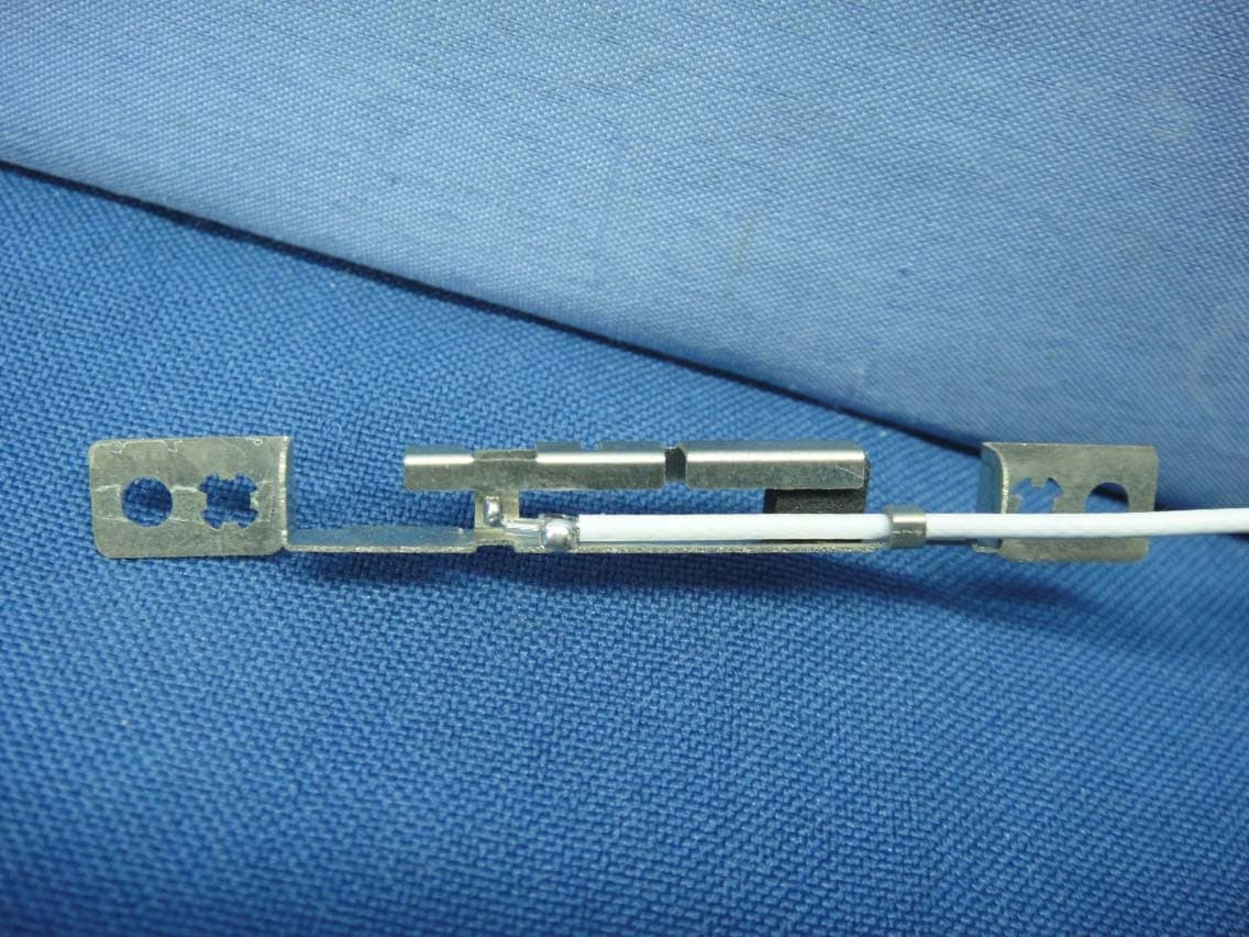
COMPANY CONFIDENTIAL•1 Specification © 2000-2002 by Atheros Communications, Inc. All rights reserved. Atheros™, 5-UP™, Driving the Wireless Future™, Atheros Driven™, Atheros Turbo Mode™, and the Air is Cleaner at 5-GHz™ are trademarks of Atheros Communications, Inc. The Atheros logo is a registered trademark of Atheros Communications, Inc. All other trademarks are the property of their respective holders. Subject to change without notice. May 21, 2003 Dualband PCB Antenna for AR5BCB-00032 CardBus Adapters General Description The dualband PCB antenna is designed specifically for PCMCIA Card applications for operation in 2.4 & 5GHz bands. The antenna is a dualband monopole antenna with diversity printed onto the PC Card PCB. Features nOperating frequencies: 2.4-2.4835 & 5.15 to 5.85 GHz for IEEE 802.11a/b/g applications nOmni-directional pattern nHigh gain: 2.0 dBi peak nDesigned for and tested with the AR5BCB- 00032 PC Cards (Cardbus) Electrical The antenna has been designed to meet the electrical characteristics shown in Table0-1. To match the antenna impedance with the trace impedance, the antenna feed is used with a substrate thickness of 10 mils and a substrate dielectric constant of 4.25 at 5 GHz. Table0-1. Antenna Electrical Characteristics ParameterSpecification Input VSWR2:1 Max. Max. gain2.0 dBi PolarizationHorizontal Frequency range2.4-2.4835 & 5.15 to 5.85 GHz Figure0-1. Dualband PCB Antenna on PCMCIA Card PCB Fab Figure0-2. Dualband PCB Antenna Layout FCCID: PPD-AR5BCB-00032
RF Exposure Info
Frequency [GHz] ε'ε''σ [S/m] ε'ε''σ[S/m]ε'ε''σ [S/m] 5.20000000047.4568 18.98795.49 73.2324 19.77155.72 47.4606 18.97985.49 5.21000000047.4274 18.98615.50 73.2297 19.78705.74 47.4227 18.98755.50 5.22000000047.4029 19.01965.52 73.1874 19.81845.76 47.3925 19.00455.52 5.23000000047.3650 19.05505.54 73.1926 19.86885.78 47.3496 19.04335.54 5.24000000047.3182 19.06875.56 73.1625 19.89015.80 47.3104 19.05185.55 5.25000000047.3100 19.07865.57 73.1366 19.92455.82 47.2982 19.08305.57 5.26000000047.2770 19.09285.59 73.1066 19.91465.83 47.2832 19.08285.58 5.27000000047.2406 19.11505.60 73.1028 19.97525.86 47.2285 19.09745.60 5.28000000047.2001 19.14965.62 73.0610 20.01065.88 47.1946 19.14425.62 5.29000000047.1724 19.17555.64 73.0353 20.02445.89 47.1719 19.16665.64 5.30000000047.1484 19.19555.66 73.0084 20.08455.92 47.1509 19.19375.66 Frequency [GHz] ε'ε''σ [S/m] ε'ε''σ[S/m]ε'ε''σ [S/m] 5.75000000045.1633 18.97666.07 72.1077 21.83186.98 45.1299 18.97116.07 5.76000000045.4106 19.21276.16 72.0844 21.88987.01 45.3732 19.21556.16 5.77000000045.6316 19.27086.19 72.0780 21.90167.03 45.6241 19.26296.18 5.78000000045.8142 19.13816.15 72.0499 21.92777.05 45.7994 19.11856.15 5.79000000045.8402 18.88516.08 72.0417 21.98197.08 45.8244 18.84166.07 5.80000000045.7323 18.52515.98 72.0268 22.01187.10 45.7103 18.49655.97 5.81000000045.5013 18.23035.89 71.9854 22.02707.12 45.4492 18.17265.87 5.82000000045.2030 18.01815.83 71.9877 22.05997.14 45.1508 17.98405.82 5.83000000044.9206 17.98085.83 71.9480 22.07877.16 44.8581 17.94725.82 5.84000000044.7204 18.14415.89 71.9397 22.11127.18 44.6346 18.11315.88 5.85000000044.6132 18.42366.00 71.9116 22.15367.21 44.5619 18.40105.99 f target [GHz] 5.24005.8000 ε' target 49.048.2 σ target [S/m] 5.356.00 ε 0 8.85419E-12 DI Water at 20°CMeas. after 5minInit. Meas. Init. Meas.DI Water at 20°CMeas. after 5min
RF Exposure Info
Uncertainty determination for SAR Zoom scan parameters 5pts×5pts×9pts(16mm×16mm×32mm), res:4mm×4mm×4mm in comparison to recommended P1528 SAR Zoom Scan parameters of 7pts×7pts×7pts(30mm×30mm×30mm, res: 5mm×5mm×5mm Victor Kee & Jae Wook Choi Purpose: To determine the uncertainty budget introduced in using a smaller measurement volume than one recommended by the IEEE P1528 SAR standard. Background: Zoom scan parameters for the determination of the Peak 1 gram Spatial average SAR is recommended at comprising 1.5 times the cube side in each direction. In the case of the 1 gram SAR, this would mean a zoom scan volume of 30mmx30mmx30mm which represents 27 times the averaging volume used. In the majority of SAR systems, this zoom scan volume is usually divided up into a measurement grid employing 7x7x7 measurement points which results in a grid resolution of 5mm and some 343 measurement points. For low frequency applications where the E-Field gradients are gradual, this resolution is adequate to fully characterize the field contours adequately. At the higher frequency bands such as the 2.45GHz and especially the 5GHz bands, the field gradients are much steeper and the hot spots more concentrated as would be expected since the penetration depths are much shorter. Maintaining the same 5mm grid resolutions in these frequency bands is not optimal to obtaining a sufficient number of data points to fully characterize the hot spot volume with reasonable spatial precision. Decreasing the grid resolution to 4mm would mean an increase in measurement points to 512 measurement points. The following table illustrates the penalties for increasing the spatial accuracy by reducing the grid resolution. Measurement Number of points Increase in Grid Resolution (mm) Matrix 30mmx30mmx30mm Zoom Scan Duration multiplier 5 7x7x7 343 1.0 4 9x9x9 729 2.1 3 11x11x11 1331 3.9 2 13x13x13 2197 6.4 1 15x15x15 3375 9.8 Table 1 From the above table, the zoom scan duration in reducing the grid resolution by 1mm represents a doubling of the number of measurement points for the specified scan volume. This directly translates into doubling up the measurement times. Currently, the zoom scan time for a 7x7x7 measurement matrix is between 20 to 30 minutes depending on the SAR system used. Most hand held devices to be tested for SAR are battery operated and are normally not designed to transmit continuously for long periods of time without significant power droop, overheating or experiencing other non-linear effects. It is therefore imperative to try and complete the zoom scans in as short a time interval as possible. A reasonable zoom scan time is under 30 minutes as longer durations may result in overstress of the device-under-test beyond its normal operating parameters. Uncertainty Analysis With this in mind, a zoom scan volume reduction can be done provided it can be shown that the uncertainty in determining the peak spatial 1g average SAR, introduced in this approach, is within acceptable limits. For the 2.45GHz band, in order to maintain the zoom scan times down below 30 minutes using a reduced grid resolution of 4mm would require a zoom volume reduction to 16mmx16mmxx32mm requiring 229 measurement points. In order to determine the uncertainty of the zoom volume scan reduction, the evaluation test function specified in the P1528 standard will be used in the post processing algorithm to determine the sensitivities of the reduced volume scan. The evaluation function given is: fxy,z,()Ae z− 2a ⋅cos πx1 2 y1 2 +⋅ 25⋅a ⋅:= E1. where x1 = x + d mm and y1 = y + d mm d - Offset value used to shift the function off center a - decay factor The target value for a=20 is given as SARref = 0.881 W/Kg accurate to 0.01% and this can be used to evaluate the post processing algorithms. To investigate the uncertainty of the reduced volume scan on the post-processing algorithm used, 7 simulations are run for the reduced scan volume with the test function offset by increasing increments of 0.5mm. These are compared to 7 additional simulations using the recommended zoom scan volume carried out using the same test function and incremental offsets. A = 1.0 [W/Kg] : arbitrary amplitude constant a = 20 [mm] : decay factor d : lateral shift of the SAR distribution [mm] L z = 16.0 : side length of the zoom scan cube L c = 10.0 : cube side length |d| ≤ (L z - L c ) / 2 = 3.0 L h = 10.0 : height of the zoom scan volume z d = 2.0 : measurement point closest to the inner surface Zoom scan volume is centered at (0, 0, L h / 2 + z d ) = (0, 0, 7.0) SAR Tolerance [%] = 100 × | (SAR eval - SAR ref ) / SAR ref | SARref = 0.881 W/Kg Spec - 5 pts ×5 pts ×9 pts (16 mm ×16 mm ×32 mm, res: 4 mm ×4 mm ×4 mm ) Function Offset SAR eval [W/Kg] SAR Tolerance [%] d [mm] (f 1 ) 1g SAR to (f 1 ) 3.0 0.878 0.374 2.5 0.878 0.378 2.0 0.877 0.451 1.5 0.878 0.378 1.0 0.878 0.374 0.5 0.878 0.367 0.0 0.878 0.386 Spec - 7 pts ×7 pts ×7 pts (30 mm ×30 mm ×30 mm, res: 5 mm ×5 mm ×5 mm ) Function Offset SAR eval [W/Kg] SAR Tolerance [%] d [mm] (f 1 ) 1g SAR to (f 1 ) 3.0 0.875 0.664 2.5 0.875 0.692 2.0 0.875 0.664 1.5 0.875 0.641 1.0 0.876 0.558 0.5 0.877 0.462 0.0 0.877 0.468 Table 2 From the above table, it can be determined that the deviation is less than 0.7% from the target value provided in the IEEE P1528 standard for both the recommended zoom scan volume as well as the reduced zoom scan volume. To determine the sensitivity of the zoom volume scan reduction over the P1528 recommended volume specified, the measurements are compared directly an it can be seen from the table below that the sensitivity in the post processing algorithm is less than 0.5%. Function offset Recommended Scan Volume Reduced Scan Volume Sensitivity d [mm] SAReval [W/Kg] SAReval [W/Kg] of reduced volume scan 3 0.875 0.878 -0.292% 2.5 0.875 0.878 -0.316% 2 0.875 0.877 -0.215% 1.5 0.875 0.878 -0.265% 1 0.876 0.878 -0.185% 0.5 0.877 0.878 -0.095% 0 0.877 0.878 -0.082% Table 3 Conclusion A reduct…
Text truncated - open the document above for the full version.
Test Report
REPORT NO: 03U2005-1 DATE: JUNE 17, 2003 EUT: 802.11a/b/g Cardbus FCC ID: PPD-AR5BCB-00032 Page 41 of 84 COMPLIANCE CERTIFICATION SERVICES DOCUMENT NO: CCSUP4031A 561F MONTEREY ROAD, MORGAN HILL, CA 95037 USA TEL: (408) 463-0885 FAX: (408) 463-0888 This report shall not be reproduced except in full, without the written approval of CCS. This document may be altered or revised by Compliance Certification Services personnel only, and shall be noted in the revision section of the document. PEAK EXCURSION HIGH CH (Turbo mode) REPORT NO: 03U2005-1 DATE: JUNE 17, 2003 EUT: 802.11a/b/g Cardbus FCC ID: PPD-AR5BCB-00032 Page 42 of 84 COMPLIANCE CERTIFICATION SERVICES DOCUMENT NO: CCSUP4031A 561F MONTEREY ROAD, MORGAN HILL, CA 95037 USA TEL: (408) 463-0885 FAX: (408) 463-0888 This report shall not be reproduced except in full, without the written approval of CCS. This document may be altered or revised by Compliance Certification Services personnel only, and shall be noted in the revision section of the document. 7.6. CONDUCTED SPURIOUS EMISSIONS LIMITS §15.407 (b) (1 & 2) For transmitters operating in the 5.15-5.35 GHz band: all emissions outside of the 5.15-5.35 GHz band shall not exceed an EIRP of -27dBm / MHz. TEST PROCEDURE Conducted RF measurements of the transmitter output are made to confirm that the EUT antenna port conducted emissions meet the specified limit and to identify any spurious signals that require further investigation or measurements on the radiated emissions site. The transmitter output is connected to the spectrum analyzer. The resolution bandwidth is set to 1 MHz. The video bandwidth is set to 1 MHz. Peak detection measurements are compared to the average EIRP limit, adjusted for the maximum antenna gain. If necessary, additional average detection measurements are made. Measurements are made over the 30 MHz to 40 GHz range with the transmitter set to the lowest, middle, and highest channels. RESULTS No non-compliance noted: REPORT NO: 03U2005-1 DATE: JUNE 17, 2003 EUT: 802.11a/b/g Cardbus FCC ID: PPD-AR5BCB-00032 Page 43 of 84 COMPLIANCE CERTIFICATION SERVICES DOCUMENT NO: CCSUP4031A 561F MONTEREY ROAD, MORGAN HILL, CA 95037 USA TEL: (408) 463-0885 FAX: (408) 463-0888 This report shall not be reproduced except in full, without the written approval of CCS. This document may be altered or revised by Compliance Certification Services personnel only, and shall be noted in the revision section of the document. SPURIOUS EMISSIONS, LOW CHANNEL (NORMAL MODE) LOW CH SPURIOUS (Normal mode) REPORT NO: 03U2005-1 DATE: JUNE 17, 2003 EUT: 802.11a/b/g Cardbus FCC ID: PPD-AR5BCB-00032 Page 44 of 84 COMPLIANCE CERTIFICATION SERVICES DOCUMENT NO: CCSUP4031A 561F MONTEREY ROAD, MORGAN HILL, CA 95037 USA TEL: (408) 463-0885 FAX: (408) 463-0888 This report shall not be reproduced except in full, without the written approval of CCS. This document may be altered or revised by Compliance Certification Services personnel only, and shall be noted in the revision section of the document. LOW CHANNEL SPURIOUS (Normal mode) REPORT NO: 03U2005-1 DATE: JUNE 17, 2003 EUT: 802.11a/b/g Cardbus FCC ID: PPD-AR5BCB-00032 Page 45 of 84 COMPLIANCE CERTIFICATION SERVICES DOCUMENT NO: CCSUP4031A 561F MONTEREY ROAD, MORGAN HILL, CA 95037 USA TEL: (408) 463-0885 FAX: (408) 463-0888 This report shall not be reproduced except in full, without the written approval of CCS. This document may be altered or revised by Compliance Certification Services personnel only, and shall be noted in the revision section of the document. SPURIOUS EMISSIONS, MID CHANNEL (NORMAL MODE) MID CH SPURIOUS (Normal mode) REPORT NO: 03U2005-1 DATE: JUNE 17, 2003 EUT: 802.11a/b/g Cardbus FCC ID: PPD-AR5BCB-00032 Page 46 of 84 COMPLIANCE CERTIFICATION SERVICES DOCUMENT NO: CCSUP4031A 561F MONTEREY ROAD, MORGAN HILL, CA 95037 USA TEL: (408) 463-0885 FAX: (408) 463-0888 This report shall not be reproduced except in full, without the written approval of CCS. This document may be altered or revised by Compliance Certification Services personnel only, and shall be noted in the revision section of the document. MID CHANNEL SPURIOUS (Normal mode) REPORT NO: 03U2005-1 DATE: JUNE 17, 2003 EUT: 802.11a/b/g Cardbus FCC ID: PPD-AR5BCB-00032 Page 47 of 84 COMPLIANCE CERTIFICATION SERVICES DOCUMENT NO: CCSUP4031A 561F MONTEREY ROAD, MORGAN HILL, CA 95037 USA TEL: (408) 463-0885 FAX: (408) 463-0888 This report shall not be reproduced except in full, without the written approval of CCS. This document may be altered or revised by Compliance Certification Services personnel only, and shall be noted in the revision section of the document. SPURIOUS EMISSIONS, HIGH CHANNEL (NORMAL MODE) HIGH CH SPURIOUS (Normal mode) REPORT NO: 03U2005-1 DATE: JUNE 17, 2003 EUT: 802.11a/b/g Cardbus FCC ID: PPD-AR5BCB-00032 Page 48 of 84 COMPLIANCE CERTIFICATION SERVICES DOCUMENT NO: CCSUP4031A 561F MONTEREY ROAD,…
Text truncated - open the document above for the full version.
Contact Information
Applicant
Paul Guckian(Vice President, Regulatory Engineering)
Technical Contact
COMPLIANCE CERTIFICATION SERVICESSTEVE CHENG
[email protected]408-463-0885
561F MONTEREY ROAD · MORGAN HILL, California · United States
Test Firm
Compliance Certification Services IncSteve Cheng
Technical Specifications
| # | Rule Parts | Frequency Range | Power Output |
|---|---|---|---|
| 1 | 15E | 5.18 GHz - 5.32 GHz | 59.00 mW |
Other Applications from Qualcomm Atheros, Inc.
PPD-QCNFA425
Sep 01, 2015Single Stream 802.11a/b/g/n/ac + BT 4.1 M.2 1216 Type Card
Equipment Class
DTS - Digital Transmission System
PPD-QCA9008-SBD1
Aug 18, 2015802.11ad MODULE
Equipment Class
DXT - Part 15 Low Power Transceiver, Rx Verified
PPD-QCNFA344AH
May 27, 2015802.11a/b/g/n/ac + BT 4.1 M.2 2230 Type Card
Equipment Class
JBP - Part 15 Class B Computing Device Peripheral
PPD-QCNFA364AH
May 27, 2015802.11a/b/g/n/ac + BT 4.1 M.2 2230 Type Card
Equipment Class
DTS - Digital Transmission System
PPD-QCNFA344A
Apr 30, 2015802.11a/b/g/n/ac + BT 4.1 M.2 2230 Type Card
Equipment Class
NII - Unlicensed National Information Infrastructure TX