PPD-AR5BMB-00044802.11 a/b/g Mini-PCI Module
Qualcomm Atheros, Inc.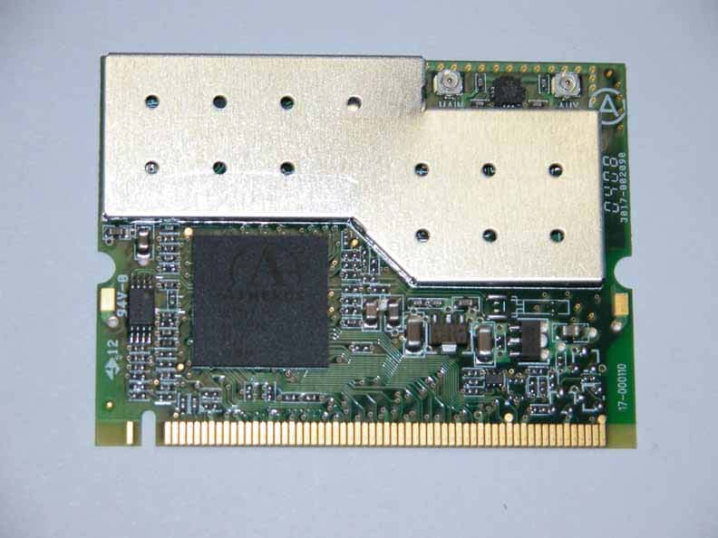
Click to zoom
Application Details
- Equipment Class
- NII - Unlicensed National Information Infrastructure TX
- Date of Grant
- Apr 29, 2004
- Application Purpose
- Original Equipment
- Date of Application
- Apr 29, 2004
- Equipment Note
- 802.11 a/b/g Mini-PCI Module
- Frequency Range
- 5250.00000000 - 5320.00000000
- Company
- Qualcomm Atheros, Inc.
- Country
- United States
Documents & Files
Document Text
Text extracted from the exhibit documents filed with the FCC. Open a document above to read the original.
Users Manual
Atheros Client Utility Help Model AR5BMB-43 (802.11b/g radio) Model AR5BMB-44(802.11a/b/g radio) PRELIMINARY March 2004 PRELIMINARY Atheros Communications, Inc. Page 2 COMPANY CONFIDENTIAL March 2004 Introduction • System Requirements Profile Management • Create or Modify a Profile • Remove a Profile • Profile Auto Selection • Switch Profiles • Configure TCP/IP • Configuring Win XP Security • EAP-TLS • EAP-TTLS • PEAP (EAP-GTC) • PEAP (EAP-MSCHAP V2) • LEAP • WPA Passphrase Check Status or Diagnostics • Check Current Status • Check Driver Information • Check Statistics Connect to Another Network Settings • Signal Strength Display • Data Display • Display Refresh Interval Tools • Tray Icon • Troubleshooting Utility • Enable/ Disable the Radio Compliance Introduction The Atheros Client Utility (ACU) is a user-mode utility designed to edit and add configuration profiles, as well as display diagnostics pertaining to a selected Atheros network interface card (wireless adapter). System Requirements • Laptop/ PC containing: • 32-bit CardBus slot (or Desktop PC with PC Card-PCI adapter) • Mini PCI • 32 MB memory or greater • 300 MHz processor or higher PRELIMINARY Atheros Communications, Inc. Page 3 COMPANY CONFIDENTIAL March 2004 Microsoft Windows 2000, Windows Millennium Edition, Windows 98 Second Edition, Windows XP, or Windows NT 4.0 (with Service Pack 6) Profile Management Configure the wireless network adapter (wireless card) from the Profile Management tab of the Atheros Client Utility. • Add a profile • Edit a profile • Import a Profile • Export a Profile • Order profiles • Switch to a different profile • Remove a profile • Connect to a Different Network The wireless network adapter works in either infrastructure mode (which uses an access point) or ad hoc mode (a group of stations participating in the wireless LAN). Create or Modify a Configuration Profile To add a new configuration profile, click New on the Profile Management tab. To modify a configuration profile, select the configuration from the Profile list and click the Modify button. The Profile Management dialog box displays the General tab . Profile Management: • Edit the General tab. • Edit the Security tab. • Edit the Advanced tab. To configure a profile for ad hoc or access point (infrastructure) mode, edit the Network Type field on the Advanced tab . Remove a Configuration Profile 1. Go to the Profile Management tab. 2. Select the profile to remove from the list of configuration profiles. 3. Click the Remove button. PRELIMINARY Atheros Communications, Inc. Page 4 COMPANY CONFIDENTIAL March 2004 Auto Profile Selection Management Including a profile in the auto selection feature allows the wireless adapter to automatically select that profile from the list of profiles and use it to connect to the network. Including a profile in auto profile selection: 1. On the Profile Management tab, click the Order Profiles button. 2. The Auto Profile Selection Management window appears, with a list of all created profiles in the Available Profiles box. 3. Highlight the profiles to add to auto profile selection, then click Add. The profiles appear in the Auto Selected Profiles box. Ordering the auto selected profiles: 1. Highlight a profile in the Auto Selected Profiles box. 2. Click Move Up or Move Down as appropriate. The first profile in the Auto Selected Profiles box has highest priority, and the last profile has lowest priority. 3. Click OK. 4. Check the Auto Select Profiles box. 5. Save the modified configuration file. When auto profile selection is enabled by checking Auto Select Profiles on the Profile Management tab, the client adapter scans for an available network. The profile with the highest priority and the same SSID as one of the found networks is the one that is used to connect to the network. If the connection fails, the client adapter tries the next highest priority profile that matches the SSID, and so on. With auto profile selection enabled, the wireless adapter scans for available networks. The highest priority profile with the same SSID as a found network is used to connect to the network. On a failed connection, the client adapter tries with the next highest priority profile. Switching to a different configuration profile 1. To switch to a different profile, go to the Profile Management tab. 2. Click on the profile name in the Profile List. 3. Click the Activate button. The Profile List provides icons that specify the operational state for that profile. The list also provides icons that specify the signal strength for that profile. See also Scan Available Networks. PRELIMINARY Atheros Communications, Inc. Page 5 COMPANY CONFIDENTIAL March 2004 Import and Export Profiles Importing a Profile 1. From the Profile Management tab, click the Import button. The Import Profile window appears. 2. Browse to the directory where the profile is located. 3. Highlight the profile name. 4. Click Open. The imported profile appears in the profiles list. Exporting a Profile 1. From the Profile Management tab, highlight the profile to export. 2. Click the Export button. The Export Profile window appears. 3. Browse to the directory to export the profile to. 4. Click Save. The profile is exported to the specified location. TCP/IP Configuration Configuring the TCP/IP Address for the network device: 1. After configuring the wireless network adapter properties, open the Control Panel and open Network and Dial-up Connections. 2. Find the Local Area Connection associated with the wireless network adapter. Right-click that connection, and click Properties. 3. Select Internet Protocol (TCP/IP) and click Properties. 4. Click the radio button Use the following IP address, then enter an IP address and Subnet mask. Assigning an IP address and Subnet mask allows stations to operate in access point mode (infrastructure mode) or in ad hoc mode and to have Internet access. Default gateway and DNS server information is also required. IP configuration infor…
Text truncated - open the document above for the full version.
Cover Letter(s)
Atheros Communications, Inc. FCC ID: PPD-AR5BMB-00044 Request for transmitter modular approval Transmitter Module Characteristics Item Requirements EUT 1 Have its own RF shielding Device is equipped with Metal shielding to cover RF section. Refer to external photos 2 Have buffered modulation/data inputs (if such inputs are provided), All inputs to the modules are buffered through logic or microprocessor inputs. 3 Have it own power supply regulation Internal 2.5V power regulator and 3.3V host supply. Refer to Schematics 4 Meet the antenna requirements of Section 15.203 Device is equipped with unique antenna ( u.FL(v)- LP-040) connector. Refer to external photos 5 Be tested in a stand-alone configuration, i.e., the antenna, AC or DC power and data input/output lines must be connected to the module but, the module must not be inside another case during testing Device was tested outside the laptop for modular approval. Refer to setup photos. 6 Be labeled with its own FCC ID number, and if the FCC ID is not visible when the module is installed inside another device, then the outside of the device into which the module is installed must also display a label referring to the enclosed module. Two proposed FCC ID label format are included in the filing. One of label is to be placed on the module and the other label is to be placed on the outside of system. Refer to FCC ID label format and location file. 7 The modular transmitter is manufactured so that the user cannot influence the operation of the transmitter that will operate outside of the scope of the regulations. Refer to “User’s Guide” Exhibit 8 Address compliance with the Commission's RF exposure limits in Sections 1.1310 and 2.1093. In addition, spread spectrum transmitters operating under Section 15.247 are required to address RF exposure compliance in accordance with Section 15.247(b)(4). Compliance with RF exposure limits.
ID Label/Location Info
PROPOSED FCC ID LABEL AND LOCATION ATHEROS COMMUNICATIONS, INC. This device complies with Part 15 of the FCC Rules. Operation is subject to the following two conditions: (1) this device may not cause harmful interference, and (2) this device must accept any interference received, including interference that may cause undesired operation. FCC ID: PPD-AR5BMB-00044 FCC ID LABEL LOCATION PROPOSED FCC ID LABEL FOR HOST DEVICE ATHEROS COMMUNICATIONS, INC. This device contains FCC ID: PPD-AR5BMB-00044
RF Exposure Info
REPORT NO: 04U2552-2 DATE: APRIL 20, 2004 EUT: 802.11 a/b/g Mini PCI Module FCC ID: PPD-AR5BMB-00044 Page 27 of 110 COMPLIANCE CERTIFICATION SERVICES DOCUMENT NO: CCSUP4031A 561F MONTEREY ROAD, MORGAN HILL, CA 95037 USA TEL: (408) 463-0885 FAX: (408) 463-0888 This report shall not be reproduced except in full, without the written approval of CCS. This document may be altered or revised by Compliance Certification Services personnel only, and shall be noted in the revision section of the document. 7.3. MAXIMUM PERMISSIBLE EXPOSURE LIMITS §1.1310 The criteria listed in Table 1 shall be used to evaluate the environmental impact of human exposure to radio-frequency (RF) radiation as specified in §1.1307(b), except in the case of portable devices which shall be evaluated according to the provisions of §2.1093 of this chapter. REPORT NO: 04U2552-2 DATE: APRIL 20, 2004 EUT: 802.11 a/b/g Mini PCI Module FCC ID: PPD-AR5BMB-00044 Page 28 of 110 COMPLIANCE CERTIFICATION SERVICES DOCUMENT NO: CCSUP4031A 561F MONTEREY ROAD, MORGAN HILL, CA 95037 USA TEL: (408) 463-0885 FAX: (408) 463-0888 This report shall not be reproduced except in full, without the written approval of CCS. This document may be altered or revised by Compliance Certification Services personnel only, and shall be noted in the revision section of the document. CALCULATIONS Given E = √ (30 * P * G) / d and S = E ^ 2 / 3770 where E = Field Strength in Volts/meter P = Power in Watts G = Numeric antenna gain d = Distance in meters S = Power Density in milliwatts/square centimeter Combining equations and rearranging the terms to express the distance as a function of the remaining variables yields: d = √ ((30 * P * G) / (3770 * S)) Changing to units of Power to mW and Distance to cm, using: P (mW) = P (W) / 1000 and d (cm) =100 * d (m) yields d = 100 * √ ((30 * (P / 1000) * G) / (3770 * S)) d = 0.282 * √ (P * G / S) where d = distance in cm P = Power in mW G = Numeric antenna gain S = Power Density in mW/cm^2 Substituting the logarithmic form of power and gain using: P (mW) = 10 ^ (P (dBm) / 10) and G (numeric) = 10 ^ (G (dBi) / 10) yields d = 0.282 * 10 ^ ((P + G) / 20) / √ S Equation (1) where d = MPE distance in cm P = Power in dBm G = Antenna Gain in dBi S = Power Density Limit in mW/cm^2 Equation (1) and the measured peak power is used to calculate the MPE distance. REPORT NO: 04U2552-2 DATE: APRIL 20, 2004 EUT: 802.11 a/b/g Mini PCI Module FCC ID: PPD-AR5BMB-00044 Page 29 of 110 COMPLIANCE CERTIFICATION SERVICES DOCUMENT NO: CCSUP4031A 561F MONTEREY ROAD, MORGAN HILL, CA 95037 USA TEL: (408) 463-0885 FAX: (408) 463-0888 This report shall not be reproduced except in full, without the written approval of CCS. This document may be altered or revised by Compliance Certification Services personnel only, and shall be noted in the revision section of the document. LIMITS From §1.1310 Table 1 (B), S = 1.0 mW/cm^2 RESULTS No non-compliance noted: NOTE: For mobile or fixed location transmitters, the minimum separation distance is 20 cm, even if calculations indicate that the MPE distance would be less. ModePower DensityOutputAntennaMPE LimitPowerGainDistance (mW/cm^2)(dBm)(dBi)(cm) 802.11a, 5.2 Lower Band1.014.834.662.66 802.11a Turbo, 5.2 Lower Band1.016.644.663.28 802.11a, 5.2 Upper Band1.017.984.663.82 802.11a Turbo, 5.2 Upper Band1.017.274.663.52
Test Report
FCC CFR47 PART 15 SUBPART E CERTIFICATION TEST REPORT FOR 802.11 a/b/g Mini PCI MODULE MODEL NUMBER: AR5BMB-44 FCC ID: PPD-AR5BMB-00044 REPORT NUMBER: 04U2552-2 ISSUE DATE: APRIL 30, 2004 Prepared for ATHEROS COMMUNICATIONS, INC. 529 ALMANOR AVENUE SUNNYVALE CA 94085, USA Prepared by COMPLIANCE CERTIFICATION SERVICES 561F MONTEREY ROAD, MORGAN HILL, CA 95037, USA TEL: (408) 463-0885 FAX: (408) 463-0888 REPORT NO: 04U2552-2 DATE: APRIL 30, 2004 EUT: 802.11 a/b/g Mini PCI Module FCC ID: PPD-AR5BMB-00044 Page 2 of 110 COMPLIANCE CERTIFICATION SERVICES DOCUMENT NO: CCSUP4031A 561F MONTEREY ROAD, MORGAN HILL, CA 95037 USA TEL: (408) 463-0885 FAX: (408) 463-0888 This report shall not be reproduced except in full, without the written approval of CCS. This document may be altered or revised by Compliance Certification Services personnel only, and shall be noted in the revision section of the document. TABLE OF CONTENTS 1. TEST RESULT CERTIFICATION.................................................................................................. 3 2. EUT DESCRIPTION.......................................................................................................................... 4 3. TEST METHODOLOGY .................................................................................................................. 5 4. FACILITIES AND ACCREDITATION .......................................................................................... 5 5. CALIBRATION AND UNCERTAINTY.......................................................................................... 6 5.1. MEASURING INSTRUMENT CALIBRATION ............................................................................. 6 5.2. MEASUREMENT UNCERTAINTY ............................................................................................... 6 5.3. TEST AND MEASUREMENT EQUIPMENT................................................................................ 7 6. SETUP OF EQUIPMENT UNDER TEST ....................................................................................... 8 7. APPLICABLE LIMITS AND TEST RESULTS ........................................................................... 10 7.1. EMISSION BANDWIDTH........................................................................................................... 10 7.2. PEAK POWER ............................................................................................................................ 18 7.3. MAXIMUM PERMISSIBLE EXPOSURE ................................................................................... 27 7.4. AVERAGE POWER..................................................................................................................... 30 7.5. PEAK POWER SPECTRAL DENSITY ....................................................................................... 31 7.6. PEAK EXCURSION .................................................................................................................... 39 7.7. CONDUCTED SPURIOUS EMISSIONS.................................................................................... 47 7.8. RADIATED EMISSIONS.............................................................................................................55 7.8.1. TRANSMITTER RADIATED SPURIOUS EMISSIONS ................................................. 55 7.8.2. TRANSMITTER RADIATED EMISSIONS ABOVE 1 GHZ WITH HIGHEST GAIN ANTENNA (TIAN01) ........................................................................................................................ 58 7.8.3. SUPPLEMENTAL TRANSMITTER RADIATED EMISSIONS ABOVE 1 GHZ WITH LOWER GAIN ANTENNA (HTL017).............................................................................................. 76 7.8.4. WORST-CASE RADIATED EMISSIONS BELOW 1 GHz ............................................. 94 7.9. POWERLINE CONDUCTED EMISSIONS .............................................................................. 102 8. SETUP PHOTOS ............................................................................................................................ 106 REPORT NO: 04U2552-2 DATE: APRIL 30, 2004 EUT: 802.11 a/b/g Mini PCI Module FCC ID: PPD-AR5BMB-00044 Page 3 of 110 COMPLIANCE CERTIFICATION SERVICES DOCUMENT NO: CCSUP4031A 561F MONTEREY ROAD, MORGAN HILL, CA 95037 USA TEL: (408) 463-0885 FAX: (408) 463-0888 This report shall not be reproduced except in full, without the written approval of CCS. This document may be altered or revised by Compliance Certification Services personnel only, and shall be noted in the revision section of the document. 1. TEST RESULT CERTIFICATION COMPANY NAME: ATHEROS COMMUNICATIONS, INC. 529 ALMANOR AVENUE SUNNYVALE, CA 94085, USA EUT DESCRIPTION: 802.11a/b/g Mini PCI module MODEL: AR5BMB-44 DATE TESTED: FEBRUARY 24 – APRIL 1, 2004 APPLICABLE STANDARDS STANDARD TEST RESULTS FCC PART 15 SUBPART E NO NON-COMPLIANCE NOTED Compliance Certification Services, Inc. tested the above equipment in accordance with the requirements set forth in the above standards. The test results show that the equipment tested is capable of demonstrating compliance with the requirements as documented in this report. Note: This document reports conditions under which testing was conducted and results of tests performed. This document may not be altered or revised in any way unless done so by Compliance Certification Services and all revisions are duly noted in the revisions section. Any alteration of this document not carried out by Compliance Certification Services will constitute fraud and shall nullify the document. Note: The 5.2 GHz band is applicable to this report; other bands of operation (2.4 and 5.8 GHz) are documented in a separate report. Approved & Released For CCS By: Tested By: MIKE HECKROTTE YAN ZHENG ENGINEERING MANAGER EMC ENGINEER COMPLIANCE CERTIFICATION SERVICES COMPLIANCE CERTIFICATION SERVICES REPORT NO: 04U2552-2 DATE: APRIL 30, 2004 EUT: 802.11 a/b/g Mini PCI Module FCC ID: PPD-AR5BMB-00…
Text truncated - open the document above for the full version.
Test Setup Photos
REPORT NO: 04U2552-2 DATE: APRIL 20, 2004 EUT: 802.11 a/b/g Mini PCI Module FCC ID: PPD-AR5BMB-00044 Page 106 of 110 COMPLIANCE CERTIFICATION SERVICES DOCUMENT NO: CCSUP4031A 561F MONTEREY ROAD, MORGAN HILL, CA 95037 USA TEL: (408) 463-0885 FAX: (408) 463-0888 This report shall not be reproduced except in full, without the written approval of CCS. This document may be altered or revised by Compliance Certification Services personnel only, and shall be noted in the revision section of the document. 8. SETUP PHOTOS ANTENNA PORT CONDUCTED RF MEASUREMENT SETUP ANTENNA PORT CONDUCTED PHOTO REPORT NO: 04U2552-2 DATE: APRIL 20, 2004 EUT: 802.11 a/b/g Mini PCI Module FCC ID: PPD-AR5BMB-00044 Page 107 of 110 COMPLIANCE CERTIFICATION SERVICES DOCUMENT NO: CCSUP4031A 561F MONTEREY ROAD, MORGAN HILL, CA 95037 USA TEL: (408) 463-0885 FAX: (408) 463-0888 This report shall not be reproduced except in full, without the written approval of CCS. This document may be altered or revised by Compliance Certification Services personnel only, and shall be noted in the revision section of the document. RADIATED RF MEASUREMENT SETUP RADIATED FRONT PHOTO REPORT NO: 04U2552-2 DATE: APRIL 20, 2004 EUT: 802.11 a/b/g Mini PCI Module FCC ID: PPD-AR5BMB-00044 Page 108 of 110 COMPLIANCE CERTIFICATION SERVICES DOCUMENT NO: CCSUP4031A 561F MONTEREY ROAD, MORGAN HILL, CA 95037 USA TEL: (408) 463-0885 FAX: (408) 463-0888 This report shall not be reproduced except in full, without the written approval of CCS. This document may be altered or revised by Compliance Certification Services personnel only, and shall be noted in the revision section of the document. RADIATED BACK PHOTO REPORT NO: 04U2552-2 DATE: APRIL 20, 2004 EUT: 802.11 a/b/g Mini PCI Module FCC ID: PPD-AR5BMB-00044 Page 109 of 110 COMPLIANCE CERTIFICATION SERVICES DOCUMENT NO: CCSUP4031A 561F MONTEREY ROAD, MORGAN HILL, CA 95037 USA TEL: (408) 463-0885 FAX: (408) 463-0888 This report shall not be reproduced except in full, without the written approval of CCS. This document may be altered or revised by Compliance Certification Services personnel only, and shall be noted in the revision section of the document. POWERLINE CONDUCTED EMISSIONS MEASUREMENT SETUP LINE CONDUCTED FRONT PHOTO REPORT NO: 04U2552-2 DATE: APRIL 20, 2004 EUT: 802.11 a/b/g Mini PCI Module FCC ID: PPD-AR5BMB-00044 Page 110 of 110 COMPLIANCE CERTIFICATION SERVICES DOCUMENT NO: CCSUP4031A 561F MONTEREY ROAD, MORGAN HILL, CA 95037 USA TEL: (408) 463-0885 FAX: (408) 463-0888 This report shall not be reproduced except in full, without the written approval of CCS. This document may be altered or revised by Compliance Certification Services personnel only, and shall be noted in the revision section of the document. END OF REPORT LINE CONDUCTED BACK PHOTO
Contact Information
Applicant
Paul Guckian(Vice President, Regulatory Engineering)
Test Firm
Compliance Certification Services IncSteve Cheng
Technical Specifications
| # | Rule Parts | Frequency Range | Power Output |
|---|---|---|---|
| 2 | 15E | 5.25 GHz - 5.32 GHz | 63.00 mW |
Other Applications from Qualcomm Atheros, Inc.
PPD-QCNFA425
Sep 01, 2015Single Stream 802.11a/b/g/n/ac + BT 4.1 M.2 1216 Type Card
Equipment Class
DTS - Digital Transmission System
PPD-QCA9008-SBD1
Aug 18, 2015802.11ad MODULE
Equipment Class
DXT - Part 15 Low Power Transceiver, Rx Verified
PPD-QCNFA344AH
May 27, 2015802.11a/b/g/n/ac + BT 4.1 M.2 2230 Type Card
Equipment Class
JBP - Part 15 Class B Computing Device Peripheral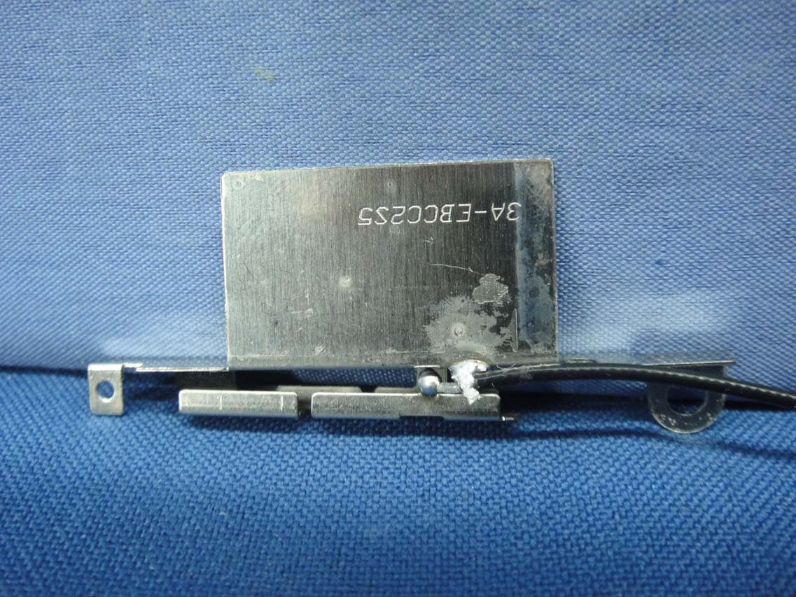
PPD-QCNFA364AH
May 27, 2015802.11a/b/g/n/ac + BT 4.1 M.2 2230 Type Card
Equipment Class
DTS - Digital Transmission System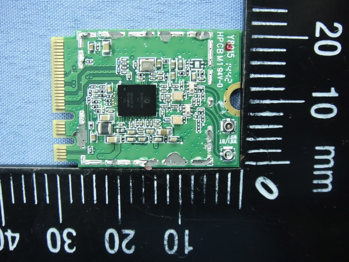
PPD-QCNFA344A
Apr 30, 2015802.11a/b/g/n/ac + BT 4.1 M.2 2230 Type Card
Equipment Class
NII - Unlicensed National Information Infrastructure TX