PPD-AR5BXB6-M802.11abg module
Qualcomm Atheros, Inc.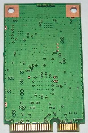
Click to zoom
Application Details
- Equipment Class
- NII - Unlicensed National Information Infrastructure TX
- Date of Grant
- Jul 13, 2005
- Application Purpose
- Original Equipment
- Date of Application
- Jul 13, 2005
- Equipment Note
- 802.11abg module
- Frequency Range
- 5180.00000000 - 5320.00000000
- Company
- Qualcomm Atheros, Inc.
- Country
- United States
Documents & Files
Document Text
Text extracted from the exhibit documents filed with the FCC. Open a document above to read the original.
Users Manual
Atheros Client Utility Help Model AR5BXB6 802.11ag WLAN Module PRELIMINARY June 2005 © 2000–2005 by Atheros Communications, Inc. All rights reserved. ATHEROS, the Atheros logo, 5-UP, Driving the Wireless Future, Atheros Driven, Atheros Turbo Mode, and the Air is Cleaner at 5-GHz are trademarks of Atheros Communications, Inc. All other trademarks are the property of their respective holders. Notice The information in this document has been carefully reviewed and is believed to be accurate. Nonetheless, this document is subject to change without notice, and Atheros Communications, Inc. (Atheros) assumes no responsibility for any inaccuracies that may be contained in this document, and makes no commitment to update or to keep current the contained information, or to notify a person or organization of any updates. Atheros reserves the right to make changes, at any time, in order to improve reliability, function or design and to attempt to supply the best product possible. Atheros does not represent that products described herein are free from patent infringement or from any other third party right. No part of this document may be reproduced, adapted or transmitted in any form or by any means, electronic or mechanical, for any purpose, except as expressly set forth in a written agreement signed by Atheros. Atheros or its affiliates may have patents or pending patent applications, trademarks, copyrights, maskwork rights or other intellectual property rights that apply to the ideas, material and information expressed herein. No license to such rights is provided except as expressly set forth in a written agreement signed by Atheros. ATHEROS MAKES NO WARRANTIES OF ANY KIND WITH REGARD TO THE CONTENT OF THIS DOCUMENT. IN NO EVENT SHALL ATHEROS BE LIABLE FOR DIRECT, INDIRECT, SPECIAL, INCIDENTAL SPECULATORY OR CONSEQUENTIAL DAMAGES ARISING FROM THE USE OR INABILITY TO USE THIS PRODUCT OR DOCUMENTATION, EVEN IF ADVISED OF THE POSSIBLITY OF SUCH DAMAGES. IN PARTICULAR, ATHEROS SHALL NOT HAVE LIABILITY FOR ANY HARDWARE, SOFTWARE, OR DATA TRANSMITTED OR OTHERWISE USED WITH THE PRODUCT, INCLUDING THE COSTS OF REPAIRING, REPLACING, INTEGRATING, INSTALLING OR RECOVERING SUCH HARDWARE, SOFTWARE OR DATA. ATHEROS SPECIFICALLY DISCLAIMS THE IMPLIED WARRANTIES OF MERCHANTIBILITY AND FITNESS FOR A PARTICULAR PURPOSE AS THEY MIGHT OTHERWISE APPLY TO THIS DOCUMENT AND TO THE IDEAS, MATERIAL AND INFORMATION EXPRESSED HEREIN. Atheros Communications, Inc. • iii COMPANY CONFIDENTIAL July 2005 Document Conventions Text Conventions bold Bold type within paragraph text indicates commands, file names, directory names, paths, output, or returned values. Example: The DK_Client package will not function unless you use the wdreg_install batch file. italic Within commands, italics indicate a variable that the user must specify. Example: mem_alloc size_in_bytes Titles of manuals or other published documents are also set in italics. Courier The Courier font indicates output or display. Example: Error:Unable to allocate memory for transfer! Menu The Menu character tag is used for menu items. Example: Choose Edit > Copy. [ ] Within commands, items enclosed in square brackets are optional parameters or values that the user can choose to specify or omit. { } Within commands, items enclosed in braces are options from which the user must choose. | Within commands, the vertical bar separates options. ... An ellipsis indicates a repetition of the preceding parameter. > The right angle bracket separates successive menu selections. Example: Start > Programs > DK > wdreg_install. Notices NOTE: This message denotes neutral or positive information that calls out important points to the text. A note provides information that may apply only in special cases. iv • Atheros Communications, Inc. July 2005 COMPANY CONFIDENTIAL Revision History Revision Description of Changes June 2005 Initial Release Atheros Communications, Inc. • v COMPANY CONFIDENTIAL July 2005 Contents Introduction ............................................................................................................... 7 System Requirements ........................................................................................ 7 Profile Management ................................................................................................. 7 Create or Modify a Configuration Profile....................................................... 7 Remove a Configuration Profile....................................................................... 8 Auto Profile Selection Management....................................................................... 8 Switching to a Different Configuration Profile..................................................... 8 Import and Export Profiles ...................................................................................... 9 Importing a Profile.................................................................................................... 9 Exporting a Profile .................................................................................................... 9 TCP/IP Configuration.............................................................................................. 9 Configuring the TCP/IP Address for the network device:................................. 9 General Tab................................................................................................................ 9 Advanced Tab.......................................................................................................... 10 Security Tab ............................................................................................................. 10 Using EAP-TLS Security ................................................................................. 11 Using EAP-TTLS Security ............................................................................... 12 Using PEAP (EAP-GTC) Security ....................................................…
Text truncated - open the document above for the full version.
Cover Letter(s)
Atheros Communications, Inc. 529 Almanor Avenue Sunnyvale CA 94085 t 408 773 5200 f 408 773 9940 www.atheros.com Federal Communications Commission 7435 Oakland Mills Road Columbia, MD 21046 4/9/2005 Dear Examiner: We request the following portions of our application be withheld from public inspection as provided under FCC section 0.459: Block Diagram Schematics Parts List Theory of Operation Antenna Specifications These documents contain details of the proprietary operation of the product not readily discernible - even to technically sophisticated individuals - from our hardware and constitute trade secrets. In addition, pursuant to Public Notice DA 04-1705, in order to comply with the marketing regulations in 47 CFR §2.803 and importation rules in 47 CFR §2.1204, while ensuring that business sensitive information remains confidential until the actual marketing of newly authorized devices, we request the commission grant short-term confidentiality for the following attachments until 45 days from the date of the Grant of Equipment Authorization: External Photos Internal Photos Test Setup Photos User Manual It is our understanding that all other attachments must be made available for public review once the grant of equipment authorization is issued. Sincerely, Michael Green Manager of Global Product Compliance
Cover Letter(s)
April 9, 2005 American TCB 6731 Whittier Ave. McLean, VA 22101 Gentlemen: This is your letter of authorization to accept our appointment of Elliott Laboratories, Inc. as Agent for Atheros Communications, Inc. to sign applications before the Commission and to make representations to you on our behalf. Elliott Laboratories is to receive and exchange data between our company and the Commission. This authorization is made pursuant to Section 2.911(c) of the FCC Rules. I hereby certify that neither Applicant nor any party to the application (officers, directors, and 5% shareholders) is subject to a denial of Federal benefits that includes FCC benefits pursuant to section 5301 of the Anti-Drug Abuse Act of 1988. 21 U.S.C. 853a. Sincerely, Michael Green Manager of Global Product Compliance
Cover Letter(s)
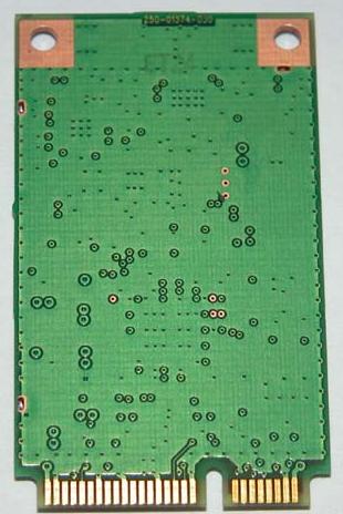
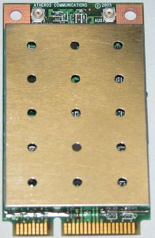
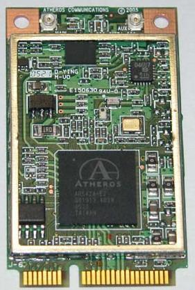
Atheros Communications, Inc. FCC ID: PPD-AR5BXB6 Request for transmitter modular approval Transmitter Module Characteristics Item Requirements EUT 1 Have its own RF shielding Device is equipped with Metal shielding to cover RF section. Refer to external photos 2 Have buffered modulation/data inputs (if such inputs are provided), All inputs to the modules are buffered through logic or microprocessor inputs. 3 Have it own power supply regulation The transmitter has its own power supply regulator. 4 Meet the antenna requirements of Section 15.203 Device is equipped with unique antenna ( u.FL(v)- LP-040) connector. Refer to external photos 5 Be tested in a stand-alone configuration, i.e., the antenna, AC or DC power and data input/output lines must be connected to the module but, the module must not be inside another case during testing Device was tested outside the laptop for modular approval. Refer to setup photos. 6 Be labeled with its own FCC ID number, and if the FCC ID is not visible when the module is installed inside another device, then the outside of the device into which the module is installed must also display a label referring to the enclosed module. Two proposed FCC ID label format are included in the filing. One of label is to be placed on the module and the other label is to be placed on the outside of system. Refer to FCC ID label format and location file. 7 The modular transmitter is manufactured so that the user cannot influence the operation of the transmitter that will operate outside of the scope of the regulations. Refer to “User’s Guide” Exhibit 8 Address compliance with the Commission's RF exposure limits in Sections 1.1310 and 2.1093. In addition, spread spectrum transmitters operating under Section 15.247 are required to Refer to MPE sections of address RF exposure compliance in accordance test reports with Section 15.247(b)(4). Transmitter meets MPE calculations of 47 CFR 1.1307(b)(1). o
Cover Letter(s)
June 29, 2005 American TCB 6731 Whittier Ave. Suite C110 McLean VA. 22101 Gentlemen: The enclosed documents constitute a formal submittal and application for a Grant of Equipment Authorization pursuant to Subpart C of Part 15 of FCC Rules (CFR 47) and RSS 210 regarding intentional radiators. Data within this report demonstrates that the equipment tested complies with the FCC and RSS 210 limits for intentional radiators. Please note that modular approval is being requested for this device for OEM installation. Elliott Laboratories, as duly authorized agent prepared this submittal. A copy of the letter of our appointment as agent is enclosed. If there are any questions or if further information is needed, please contact Elliott Laboratories for assistance. Sincerely, Mark Briggs Principal Engineer MB/jls Enclosures: Agent Authorization Letter Emissions Test Report with Exhibits
Cover Letter(s)
American Telecommunications Certification Body Inc. 6731 Whittier Ave, McLean, VA 22101 July 11, 2005 RE: FCC ID: PPD-AR5BXB6-M_ATCB002583 Attention: I have a few comments on this Application. Please note that further comments may arise in response to answers provided to the questions below. 1. Please note that the report states two antennas that were used for radiated testing. Please note that the spreadsheet listing antennas only states “omnidirectional”. Please note that omnidirectional is not an antenna type but a description of the radiation pattern produced by many antenna types. Some omnidirectional antennae types are: collinear, Omnidirectional patch, and certain dipoles (i.e. vertically oriented ¼ wave and ½ wave dipoles emit and are considered a somewhat omnidirectional pattern antenna). Please provide clarification/verification on the types of antennae listed in the spread sheet (i.e. what type omnidirectional antenna are they). If there are multiple antenna types, please provide radiated emissions testing for the highest gain antenna of each type. 2. Please note that the 731 for the 15.247 device lists NII as the equipment code and 15E as the the rule part under which the device will be operated. Please note that this should be DTS and 15.247. Please correct the 731 to reflect the equipment code for the device seeking certification. 3. FYI – page 29 of the manual states, “The antenna(s) used for this transmitter must not be co- located or operated in conjunction with any other antenna or transmitter.” It appears from the application that a Bluetooth module FCC ID number MCLJ07H081 can be collocated. This should be addressed in the non-collocation statement. Dennis Ward mailto:[email protected] The items indicated above must be submitted before processing can continue on the above referenced application. Failure to provide the requested information may result in application termination. Correspondence should be considered part of the permanent submission and may be viewed from the Internet after a Grant of Equipment Authorization is issued. Please do not respond to this correspondence using the email reply button. In order for your response to be processed expeditiously, you must submit your documents through the AmericanTCB.com website. Also, please note that partial responses increase processing time and should not be submitted. Any questions about the content of this correspondence should be directed to the sender.
Cover Letter(s)
July 12, 2005 Dennis Ward American TCB RE: FCC ID: PPD-AR5BXB6-M_ATCB002583 1. Please note that the report states two antennas that were used for radiated testing. Please note that the spreadsheet listing antennas only states “omnidirectional”. Please note that omnidirectional is not an antenna type but a description of the radiation pattern produced by many antenna types. Some omnidirectional antennae types are: collinear, Omnidirectional patch, and certain dipoles (i.e. vertically oriented ¼ wave and ½ wave dipoles emit and are considered a somewhat omnidirectional pattern antenna). Please provide clarification/verification on the types of antennae listed in the spread sheet (i.e. what type omnidirectional antenna are they). If there are multiple antenna types, please provide radiated emissions testing for the highest gain antenna of each type. All of the antennas listed are inverted F antennas (aka PIFA and/or bent metal), designed for installation into laptop PCs. The antenna list has been updated to include a statement at the bottom of the list identifying all antennas as this type. Test were performed using the antennas with the highest gains in each band. 2. Please note that the 731 for the 15.247 device lists NII as the equipment code and 15E as the rule part under which the device will be operated. Please note that this should be DTS and 15.247. Please correct the 731 to reflect the equipment code for the device seeking certification. The form 731 has been updated to reflect DTS and 15.247.. 3. FYI – page 29 of the manual states, “The antenna(s) used for this transmitter must not be collocated or operated in conjunction with any other antenna or transmitter.” It appears from the application that a Bluetooth module FCC ID number MCLJ07H081 can be collocated. This should be addressed in the non-collocation statement. The manual has been modified to cover this module and the AR5BXB6 module. Hopefully the wording clarifies the collocation and BIOS locking issues for each module. Modified Manual, Form 731 (DTS) and Antenna List documents have been uploaded to the ATCB website. Regards, Mark Briggs
ID Label/Location Info
Label Dimensions 52mm x 38mm -M -M -M IC: 4104A-AR5BXB6
RF Exposure Info
MPE Calculations The device is not a portable device (i.e. intended to be worn on the body or be hand- held), so it is classified as being either a mobile device or a fixed mounted device. The OEM installation requires a minimum separation distance of at least 20cm, consistent with this classification. FCC part 1.1310, Table 1 limits the power density for uncontrolled exposure. The power density, P d (mW/cm 2 ) calculated from the maximum EIRP, P t (mW) and the distance, d (m), between the transmitting antenna and the closest person, can be calculated using: P d = P t /(4 πd 2 ) Frequency MPE Limit (mW/cm 2 ) Output Power (mW) Max. Antenna Gain (dBi) EIRP (mW) Pd at 20cm (mW/cm 2 ) Distance where Pd = limit (cm) 2412 to 2462 MHz 1.00 190.5 3.6 436.5 0.09 5.9 5745 to 5825 MHz 1.00 141.3 5.3 478.6 0.10 6.2 5180 to 5320 MHz 1.00 40.7 5.6 147.9 0.03 3.4 As shown in the calculations above, the power density 20cm from the device is below the maximum permitted level for uncontrolled exposure.
Test Report
File: R60260 Page 1 of 20 2016-01 Electromagnetic Emissions Test Report and Application for Grant of Equipment Authorization pursuant to: FCC Part 15, Subpart C (15.247 – DTS) FCC Part 15, Subpart E (UNII) and Industry Canada RSS 210 Issue 5 for an Intentional Radiator on the Atheros Communications, Inc. Model: AR5BXB6-M 802.11 a/b/g PCI Express Module FCC ID: PPD-AR5BXB6-M UPN: 4105-AR5BCB6 GRANTEE: Atheros Communications, Inc. 529 Almanor Sunnyvale, CA 94085 TEST SITE: Elliott Laboratories, Inc. 684 W. Maude Avenue Sunnyvale, CA 94086 REPORT DATE: June 29, 2005 FINAL TEST DATE: June 21, 2005 AUTHORIZED SIGNATORY: ______________________________ Mark Briggs Principal Engineer Elliott Laboratories, Inc. is accredited by the A2LA, certificate number 2016-01, to perform the test(s) listed in this report. This report shall not be reproduced, except in its entirety, without the written approval of Elliott Laboratories, Inc. Elliott Laboratories, Inc. -- EMC Department Test Report Report Date: June 29, 2005 File: R60260 Page 2 of 20 Pages DECLARATIONS OF COMPLIANCE Equipment Name and Model: AR5BXB6-M 802.11 a/b/g PCI Express Module Manufacturer: Atheros Communications, Inc. 529 Almanor Sunnyvale, CA 94085 Tested to applicable standards: RSS-210, Issue 5, November 2001 (Low Power License-Exempt Radiocommunication Devices) FCC Part 15.247 (DTS) FCC Part 15 E (UNII) Measurement Facility Description Filed With Department of Industry: Departmental Acknowledgement Number: IC2845 SV1 Dated August 16, 2004 Departmental Acknowledgement Number: IC2845 SV2 Dated August 16, 2004 Departmental Acknowledgement Number: IC2845 SV3 Dated August 16, 2004 I declare that the testing was performed or supervised by me; that the test measurements were made in accordance with the above mentioned departmental standards (through the use of ANSI C63.4:2003 as detailed in section 5.3 of RSS-210, Issue 5); and that the equipment performed in accordance with the data submitted in this report. Signature ______________________________ Name Mark Briggs Title Principal Engineer Company Elliott Laboratories Inc. Address 684 W. Maude Ave Sunnyvale, CA 94086 USA Date: June 29, 2005 Maintenance of compliance with the above standards is the responsibility of the manufacturer. Any modification of the product which may result in increased emissions should be checked to ensure compliance has been maintained (i.e., printed circuit board layout changes, different line filter, different power supply, harnessing or I/O cable changes, etc.). Elliott Laboratories, Inc. -- EMC Department Test Report Report Date: June 29, 2005 File: R60260 Page 3 of 20 Pages TABLE OF CONTENTS COVER PAGE...................................................................................................................................................................................1 DECLARATIONS OF COMPLIANCE......................................................................................................................................2 TABLE OF CONTENTS..............................................................................................................................................................3 SCOPE............................................................................................................................................................................................4 OBJECTIVE...................................................................................................................................................................................4 SUMMARY OF RESULTS...........................................................................................................................................................5 FCC 15.247 / RSS 210 6.2.2(O) – 2400 – 2483.5 MHZ BAND...............................................................................................5 FCC 15.247 / RSS 210 6.2.2(O) – 5725-5850 MHZ BAND.....................................................................................................6 FCC 15 E / RSS 210 6.2.2(Q1) – 5150 - 5350 MHZ BAND.....................................................................................................7 FCC AND RSS 210 REQUIREMENTS COMMON TO ALL OPERATING BANDS.........................................................8 MEASUREMENT UNCERTAINTIES....................................................................................................................................8 EQUIPMENT UNDER TEST (EUT) DETAILS..........................................................................................................................9 GENERAL...................................................................................................................................................................................9 OTHER EUT DETAILS .............................................................................................................................................................9 ENCLOSURE..............................................................................................................................................................................9 MODIFICATIONS.....................................................................................................................................................................9 SUPPORT EQUIPMENT.........................................................................................................................................................10 EUT INTERFACE PORTS......................................................................................................................................................10 EUT OPERATION DURING TESTING.................................................................................................................................10 ANTENNA REQUIREMENTS...............................................................................................…
Text truncated - open the document above for the full version.
Test Setup Photos
Elliott Laboratories, Inc. -- EMC Department Test Report Report Date: June 29, 2005 EXHIBIT 3: Test Configuration Photographs 5 Pages Elliott Laboratories, Inc. -- EMC Department Test Report Report Date: June 29, 2005 Radiated Emissions Test Configuration Photographs Elliott Laboratories, Inc. -- EMC Department Test Report Report Date: June 29, 2005 Elliott Laboratories, Inc. -- EMC Department Test Report Report Date: June 29, 2005 Elliott Laboratories, Inc. -- EMC Department Test Report Report Date: June 29, 2005 AC Power Line Conducted Emissions Test Configuration Photographs Elliott Laboratories, Inc. -- EMC Department Test Report Report Date: June 29, 2005
Contact Information
Applicant
Paul Guckian(Vice President, Regulatory Engineering)
Technical Contact
Test Firm
Elliott Laboratories LLCDavid Bare
Technical Specifications
| # | Rule Parts | Frequency Range | Power Output |
|---|---|---|---|
| 1 | 15E | 5.18 GHz - 5.32 GHz | 41.00 mW |
Other Applications from Qualcomm Atheros, Inc.
PPD-QCNFA425
Sep 01, 2015Single Stream 802.11a/b/g/n/ac + BT 4.1 M.2 1216 Type Card
Equipment Class
DTS - Digital Transmission System
PPD-QCA9008-SBD1
Aug 18, 2015802.11ad MODULE
Equipment Class
DXT - Part 15 Low Power Transceiver, Rx Verified
PPD-QCNFA344AH
May 27, 2015802.11a/b/g/n/ac + BT 4.1 M.2 2230 Type Card
Equipment Class
JBP - Part 15 Class B Computing Device Peripheral
PPD-QCNFA364AH
May 27, 2015802.11a/b/g/n/ac + BT 4.1 M.2 2230 Type Card
Equipment Class
DTS - Digital Transmission System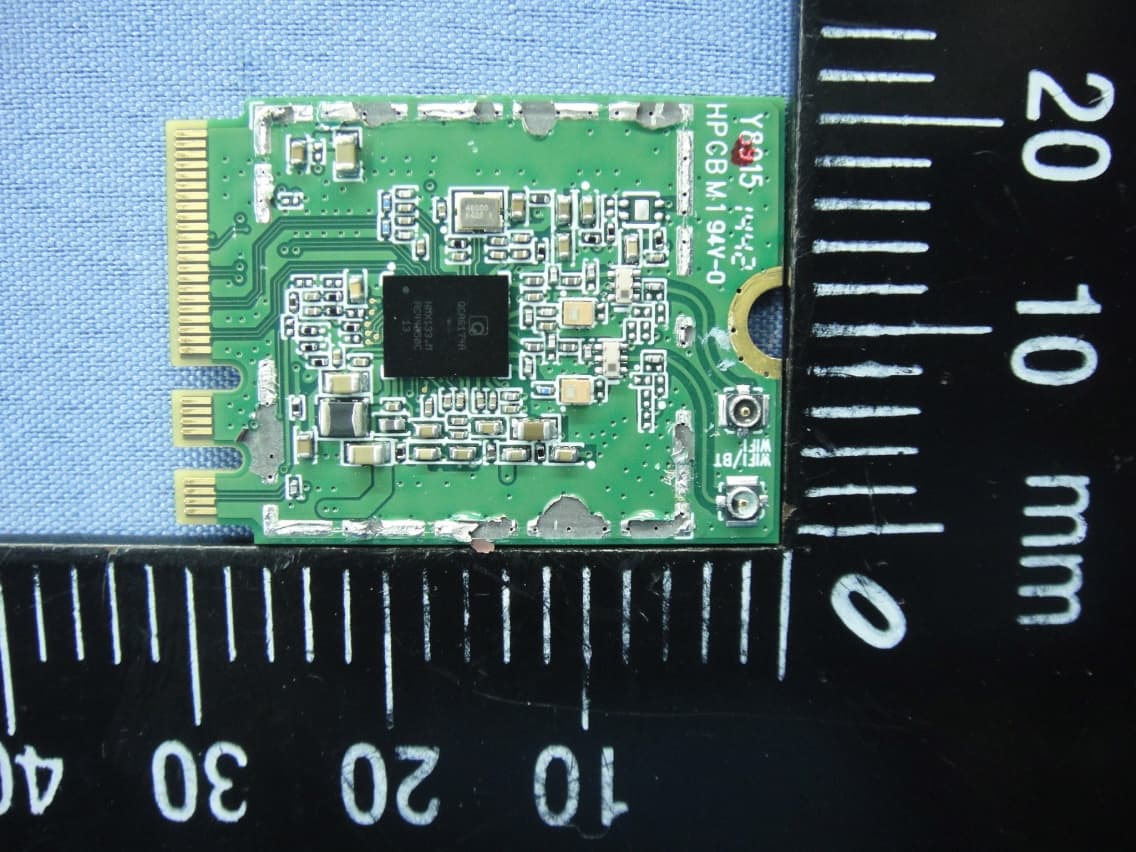
PPD-QCNFA344A
Apr 30, 2015802.11a/b/g/n/ac + BT 4.1 M.2 2230 Type Card
Equipment Class
NII - Unlicensed National Information Infrastructure TX