PPD-AR6103AR6103 802.11n 1x1 WLAN SIP
Qualcomm Atheros, Inc.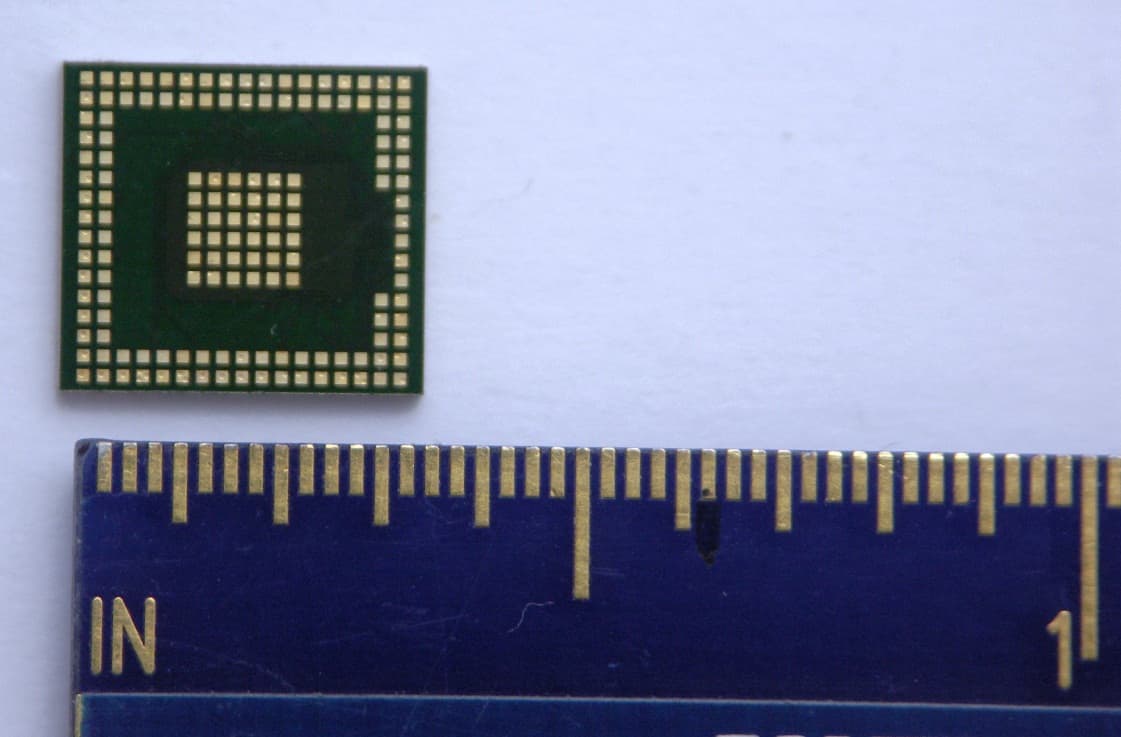
Click to zoom
Application Details
- Equipment Class
- DTS - Digital Transmission System
- Date of Grant
- Mar 13, 2011
- Application Purpose
- Original Equipment
- Date of Application
- Mar 03, 2011
- Equipment Note
- AR6103 802.11n 1x1 WLAN SIP
- Frequency Range
- 2412.00000000 - 2462.00000000
- Company
- Qualcomm Atheros, Inc.
- Country
- United States
Documents & Files
Document Text
Text extracted from the exhibit documents filed with the FCC. Open a document above to read the original.
Users Manual
Atheros Communications, Inc. Company Confidential 1 - DRAFT Atheros AR6103 SiP Modular Certification Instructions to OEM Integrators Jan-11 Atheros Communications, Inc. Company Confidential 2 - DRAFT © 2000–2010 by Atheros Communications, Inc. All rights reserved. Atheros ® , Atheros Driven ® , Atheros XR ® , Driving the Wireless Future ® , ROCm ® , Super AG ® , Super G ® , Total 802.11n ® , and Wake on Wireless ® are registered by Atheros Communications, Inc. Atheros SST™, Signal- Sustain Technology™, the Air is Cleaner at 5-GHz™, XSPAN™, Wireless Future. Unleashed Now.™, and 5- UP™ are trademarks of Atheros Communications, Inc. The Atheros logo is a registered trademark of Atheros Communications, Inc. All other trademarks are the property of their respective holders. Notice The information in this document has been carefully reviewed and is believed to be accurate. Nonetheless, this document is subject to change without notice, and Atheros Communications, Inc. (Atheros) assumes no responsibility for any inaccuracies that may be contained in this document, and makes no commitment to update or to keep current the contained information, or to notify a person or organization of any updates. Atheros reserves the right to make changes, at any time, in order to improve reliability, function or design and to attempt to supply the best product possible. Atheros does not represent that products described herein are free from patent infringement or from any other third party right. No part of this document may be reproduced, adapted or transmitted in any form or by any means, electronic or mechanical, for any purpose, except as expressly set forth in a written agreement signed by Atheros. Atheros or its affiliates may have patents or pending patent applications, trademarks, copyrights, maskwork rights or other intellectual property rights that apply to the ideas, material and information expressed herein. No license to such rights is provided except as expressly set forth in a written agreement signed by Atheros. ATHEROS MAKES NO WARRANTIES OF ANY KIND WITH REGARD TO THE CONTENT OF THIS DOCUMENT. IN NO EVENT SHALL ATHEROS BE LIABLE FOR DIRECT, INDIRECT, SPECIAL, INCIDENTAL SPECULATORY OR CONSEQUENTIAL DAMAGES ARISING FROM THE USE OR INABILITY TO USE THIS PRODUCT OR DOCUMENTATION, EVEN IF ADVISED OF THE POSSIBLITY OF SUCH DAMAGES. IN PARTICULAR, ATHEROS SHALL NOT HAVE LIABILITY FOR ANY HARDWARE, SOFTWARE, OR DATA TRANSMITTED OR OTHERWISE USED WITH THE PRODUCT, INCLUDING THE COSTS OF REPAIRING, REPLACING, INTEGRATING, INSTALLING OR RECOVERING SUCH HARDWARE, SOFTWARE OR DATA. ATHEROS SPECIFICALLY DISCLAIMS THE IMPLIED WARRANTIES OF MERCHANTIBILITY AND FITNESS FOR A PARTICULAR PURPOSE AS THEY MIGHT OTHERWISE APPLY TO THIS DOCUMENT AND TO THE IDEAS, MATERIAL AND INFORMATION EXPRESSED HEREIN. Atheros Communications, Inc. Company Confidential 3 - DRAFT Revision History Revision Description of Changes July 2010 Initial Release Jan 2011 Updated SAR Details Read in Conjunction with This Document This document must be read in conjunction with the document “AR6103 SiP Module – Certified Antennas”. This document describes the required conditions/limitations and actions by end integrator. Failure to follow the requirements in this document will invalidate the FCC Certification. Regulatory Warning regarding allowed Antennas and SiP module implementation by End Integrators The Atheros AR6103 SiP module (FCCID: PPD-AR6103) may only be used with the antenna options specified in the separate document referenced above. You must contact your Atheros representative to discuss any proposed deviations from the specifications below. No deviation may be made without prior written agreement with Atheros. Any such deviation may require retesting and additional FCC certification submissions before being accepted. Atheros Communications, Inc. Company Confidential 4 - DRAFT Introduction This document describes mandatory steps required by the OEM integrator when designing and manufacturing any host PC, netbook or handheld system utilizing an Atheros SiP (System in Package) radio module. Also refer to the Atheros Regulatory Compliance Guide available on the Atheros customer support site and from your Atheros customer support contact person. This document lists the mandatory responsibilities and actions of the OEM integrator. Failure to comply with all requirements and conditions in this document, may result in non-compliance of the host PC with FCC rules and invalidate the Atheros FCC certification for the module. This guide applies to WLAN Client modules that act under control of an Access Point. This document does not apply to a Client module or Access Point with radar detection feature. Allowed Antennas to be Used with the Radio Module The Integrator must request from Atheros sales or regulatory contact person the current version of the document the document “AR6103 SiP Module – Certified Antennas” which specifies the allowable antennas and connection method for use with the certified SiP Module. You must contact the Atheros Regulatory Group to discuss necessary actions where alternate antenna models or connection schemes are desired by the end integrator. Any such deviations from the Certified Antenna specification provided by Atheros must not be implemented without prior written acceptance. Unauthorized deviations may invalidate the FCC certification of the SiP Module. Antenna Placement and RF Hazard (SAR) Compliance For host PCs or systems certified as FCC Mobile Category devices, the FCC Grant of approval for the Atheros module is only valid when the Integrator ensures antenna placement in the host system maintains at least 20 cm separation between any part of the antenna element(s) and any part of the end user’s body (considering their likely or usual operation position and grip). This spacing is naturally met by non-Mobile systems such as Access Points or Desktop PCs. Laptop PCs typically have integrated antennas placed…
Text truncated - open the document above for the full version.
Cover Letter(s)
Atheros Communications, Inc. 1700 Technology Drive, San Jose, CA 95110 t 408 773 5200 f 408-773-9940 www.atheros.com Date: 2011/1/4 General declaration We, Atheros Communications, Inc. declares that device does not have “Ad Hoc on non-US frequencies” while applying for the follow product. FCC ID: PPD-AR6103 If you have any questions regarding the authorization, please don’t hesitate to contact us. Thank you! --------------------------------------------------------------------------- Michael Green / Manager, Global Product Compliance Atheros Communications, Inc.
Cover Letter(s)
Applicant/Grantee Atheros Communications Inc. FCC ID: PPD- AR6103 Section 15.212 Modular Transmitters Request for Modular Approval Request for Limited Modular Approval Requirements EUT Conditions Comply (Y/N) Single Modular Approval Requirements 1 The radio elements of the modular transmitter must have their own shielding. The physical crystal and tuning capacitors may be located external to the shielded radio elements. SiP package has a full Metallic coating. Y 2 The modular transmitter must have buffered modulation/data inputs (if such inputs are provided) to ensure that the module will comply with Part 15 requirements under conditions of excessive data rates or over-modulation. All inputs to the modules are buffered through logic or microprocessor inputs. Y 3 The modular transmitter must have its own power supply regulation. The transmitter has its own power supply regulator. Y 4 The modular transmitter must comply with the antenna and transmission system requirements of Sections 15.203, 15.204(b) and 15.204(c). The antenna must either be permanently attached or employ a “unique” antenna coupler (at all connections between the module and the antenna, including the cable). The “professional installation” provision of Section 15.203 is not applicable to modules but can apply to limited modular approvals under paragraph (b) of this section. Device complies with 15.203 & 15.204(c) via a permanent trace between SiP antenna output and the U.FL connector or integrated antenna. Y 5 The modular transmitter must be tested in a stand-alone configuration, i.e., the module must not be inside another device during testing for compliance with Part 15 requirements. Unless the transmitter module will be battery powered, it must comply with the AC line conducted requirements found in Section 15.207. AC or DC power lines and data input/output lines connected to the module must not contain ferrites, unless they will be marketed with the module (see Section 15.27(a)). The length of these lines shall be the length typical of actual use or, if that length is unknown, at least 10 centimeters to insure that there is no coupling between Device was tested outside the host for modular approval. Refer to setup photos. Y the case of the module and supporting equipment. Any accessories, peripherals, or support equipment connected to the module during testing shall be unmodi ed and commercially available (see Section 15.31(i)). 6 The modular transmitter must be equipped with either a permanently a xed label or must be capable of electronically displaying its FCC identi cation number. (A) If using a permanently a xed label, the modular transmitter must be labeled with its own FCC identi cation number, and, if the FCC identi cation number is not visible when the module is installed inside another device, then the outside of the device into which the module is installed must also display a label referring to the enclosed module. This exterior label can use wording such as the following: “Contains Transmitter Module FCC ID: XYZMODEL1” or “Contains FCC ID: XYZM ODEL1.” Any similar wording that expresses the same meaning may be used. The Grantee may either provide such a label, an example of which must be included in the application for equipment authorization, or, must provide adequate instructions along with the module which explain this requirement. In the latter case, a copy of these instructions must be included in the application for equipment authorization. (B) If the modular transmitter uses an electronic display of the FCC identi cation number, the information must be readily accessible and visible on the modular transmitter or on the d evice in which it is installed. If the module is installed inside another device, then the outside of the device into which the module is installed must display a label referring to the enclosed module. This exterior label can use wording such as the following: “Contains FCC certi ed transmitter module(s).” Any similar wording that expresses the same meaning may be used. The user manual must include instructions on how to access the electronic display. A copy of these instructions must be included in the application for equipment authorization. 7 The modular transmitter must comply with requirements that ordinarily apply to a complete transmitter and the manufacturer must provide adequate instructions along with the module to explain any such requirements. A copy of these instructions must be included in the Refer to “Instuctions to OEM Integrators”. Y SiP package is too small to a x label or readable text with FCCID. End Integrators are instructed to label host device with the required text: Contains FCC ID: PPD-AR6103 and to instruct where to nd the FCCID on the product. application for equipment authorization. 8 The modular transmitter must comply with any applicable RF exposure requirements in its final configuration. Transmitter meets RF Exposure requirements. of Refer to submitted test reports. . Y A limited modular approval may be granted for single or split modular transmitters that do not comply with all of the above requirements, e.g., shielding, minimum signaling amplitude, buffered modulation/data inputs, or power supply regulation, if the manufacturer can demonstrate by alternative means in the application for equipment authorization that the modular transmitter meets all the applicable Part 15 requirements under the operating conditions in which the transmitter will be used. Limited modular approval also may be granted in those instances where compliance with RF exposure rules is demonstrated only for particular product configurations. The applicant for certification must state how control of the end product into which the module will be installed will be maintained such that full compliance of the end product is always ensured.
Cover Letter(s)
Atheros Communications, Inc. 1700 Technology Drive, San Jose, CA 95110 t 408 773 5200 f 408-773-9940 www.atheros.com Date:2011/3/15 Federal Communications Commission 7435 Oakland Mills Road Columbia MD 21046 Subject: Request for Confidentiality FCC ID: PPD-AR6103 To Whom It May Concern: Pursuant to the provisions of Sections 0.457 and 0.459 of the Commission’s rules (47 CFR §§ 0.457, 0.459), we are requesting the Commission to withhold the following attachments as confidential document from public disclosure indefinitely. Schematic Diagram Block Diagram Theory of Operation AR6103 SiP Module – Certified Antennas Above mentioned document contains detailed system and equipment description are considered as proprietary information in operation of the equipment. The public disclosure of above documents might be harmful to our company and would give competitor an unfair advantage in the market. Pursuant to DA 04-1705 of the Commission’s Rules, we request short-term confidential treatment for the following information until September 1, 2011 of Equipment Authorization in order to ensure sensitive business information remains confidential until the actual marketing of the device: External Photos Internal Photos Test Setup Photos AR6103 FCC Instructions to end Integrators for SiP Modules It is our understanding that all measurement test reports, FCC ID label format and correspondent during certification review process cannot be granted as confidential documents and those information will be available for public review once the grant of equipment authorization is issued. Best Regards Michael Green / Manager, Global Product Compliance Atheros Communications, Inc.
External Photos
Page 1 CONSTRUCTION PHOTOS OF EUT EUT + PIFA antenna Page 2 Page 3 EUT + Chip antenna Page 4 EUT + Printed antenna
External Photos
PPD-AR6103 AR6103 SiP Module Photos March 2, 2011 _______________________________________________________________________________ Atheros Confidential and Proprietary Page 1 of 1 Figure 1. Module Top Side Figure 2. Module Bottom Side
ID Label/Location Info
PROPOSED HOST LABEL ATHEROS COMMUNICATIONS, INC. This device complies with Part 15 of the FCC Rules. Operation is subject to the following two conditions: (1) this device may not cause harmful interference, and (2) this device must accept any interference received, including interference that may cause undesired operation. Contains TX FCC ID: PPD-AR6103 Model:AR6103
ID Label/Location Info
PROPOSED MODULE LABEL PPD-AR6103 - Label sticker affixed to top of Module FCC ID: PPD- AR6103 Atheros Model AR6103
Internal Photos
Page 5 Page 6 Page 7
RF Exposure Info
Report No.: SA991214E01 Report Format Version 4.0.0 1 RF EXPOSURE REPORT REPORT NO.: SA991214E01 MODEL NO.: AR6103 FCC ID: PPD-AR6103 ACCORDING: FCC Guidelines for Human Exposure IEEE C95.1 APPLICANT: Atheros Communications, Inc. ADDRESS: 1700 Technology Drive, San Jose, CA 95110 ISSUED BY: Bureau Veritas Consumer Products Services (H.K.) Ltd., Taoyuan Branch Hsin Chu Laboratory LAB ADDRESS: No. 81-1, Lu Liao Keng, 9th Ling,Wu Lung Tsuen, Chiung Lin Hsiang, Hsin Chu Hsien 307, Taiwan Report No.: SA991214E01 Report Format Version 4.0.0 2 1. RF EXPOSURE LIMIT LIMITS FOR MAXIMUM PERMISSIBLE EXPOSURE (MPE) FREQUENCY RANGE (MHz) ELECTRIC FIELD STRENGTH (V/m) MAGNETIC FIELD STRENGTH (A/m) POWER DENSITY (mW/cm 2 ) AVERAGE TIME (minutes) LIMITS FOR GENERAL POPULATION / UNCONTROLLED EXPOSURE 300-1500 ... ... F/1500 30 1500-100,000 ... ... 1.0 30 F = Frequency in MHz 2. MPE CALCULATION FORMULA Pd = (Pout*G) / (4*pi*r2) where Pd = power density in mW/cm2 Pout = output power to antenna in mW G = gain of antenna in linear scale Pi = 3.1416 R = distance between observation point and center of the radiator in cm 3. CLASSIFICATION The antenna of this product, under normal use condition, is at least 20cm away from the body of the user. So, this device is classified as Mobile Device. Antenna information: No. Brand Model Gain(dBi) (included cable loss) Antenna Type Connector Cable Loss(dB) Cable Length 1 WNC 81-EBJ15.005 3.62 PIFA IPEX 1.15 300mm 2 N.A. AF 216M245001 1.8 Chip N.A. N.A. N.A. 3 N.A. Z 2 Printed N.A. N.A. N.A. Report No.: SA991214E01 Report Format Version 4.0.0 3 4. CALCULATION RESULT OF MAXIMUM CONDUCTED POWER FREQUENCY BAND (MHz) MAX POWER (dBm) ANTENNA GAIN (dBi) DISTANCE (cm) POWER DENSITY (mW/ cm 2 ) LIMIT (mW/cm 2 ) 2412-2462 21.6 3.62 20 0.066 1.00 --- END ---
Test Report
Report No.: RF991214E01 1 Report Format Version 4.0.0 FCC TEST REPORT REPORT NO.: RF991214E01 MODEL NO.: AR6103 RECEIVED: Dec. 14, 2010 TESTED: Jan. 03 to 21, 2011 ISSUED: Feb. 09, 2011 APPLICANT: Atheros Communications, Inc. ADDRESS: 1700 Technology Drive, San Jose, CA 95110 ISSUED BY: Bureau Veritas Consumer Products Services (H.K.) Ltd., Taoyuan Branch Hsin Chu Laboratory LAB ADDRESS: No. 81-1, Lu Liao Keng, 9th Ling, Wu Lung Tsuen, Chiung Lin Hsiang, Hsin Chu Hsien 307, Taiwan TEST LOCATION (1): No. 81-1, Lu Liao Keng, 9th Ling,Wu Lung Tsuen, Chiung Lin Hsiang, Hsin Chu Hsien 307, Taiwan TEST LOCATION (2): No.49, Ln. 206, Wende Rd., Shangshan Tsuen, Chiung Lin Hsiang, Hsin Chu Hsien 307, Taiwan This test report consists of 144 pages in total. It may be duplicated completely for legal use with the approval of the applicant. It should not be reproduced except in full, without the written approval of our laboratory. The client should not use it to claim product certification, approval, or endorsement by TAF or any government agencies. The test results in the report only apply to the tested sample. Report No.: RF991214E01 2 Report Format Version 4.0.0 Table of Contents RELEASE CONTROL RECORD........................................................................................5 1. CERTIFICATION....................................................................................................6 2. SUMMARY OF TEST RESULTS............................................................................7 2.1 MEASUREMENT UNCERTAINTY..........................................................................8 3. GENERAL INFORMATION.....................................................................................9 3.1 GENERAL DESCRIPTION OF EUT.......................................................................9 3.2 DESCRIPTION OF ANTENNA.............................................................................11 3.3 DESCRIPTION OF TEST MODES.......................................................................12 3.3.1 TEST MODE APPLICABILITY AND TESTED CHANNEL DETAIL........................13 3.4 GENERAL DESCRIPTION OF APPLIED STANDARDS.......................................16 3.5 DESCRIPTION OF SUPPORT UNITS..................................................................17 3.6 CONFIGURATION OF SYSTEM UNDER TEST...................................................17 4. TEST TYPES AND RESULTS..............................................................................18 4.1 CONDUCTED EMISSION MEASUREMENT........................................................18 4.1.1 LIMITS OF CONDUCTED EMISSION MEASUREMENT......................................18 4.1.2 TEST INSTRUMENTS..........................................................................................18 4.1.3 TEST PROCEDURES..........................................................................................19 4.1.4 DEVIATION FROM TEST STANDARD.................................................................19 4.1.5 TEST SETUP.......................................................................................................20 4.1.6 EUT OPERATING CONDITIONS.........................................................................20 4.1.7 TEST RESULTS...................................................................................................21 4.2 RADIATED EMISSION MEASUREMENT.............................................................23 4.2.1 LIMITS OF RADIATED EMISSION MEASUREMENT...........................................23 4.2.2 TEST INSTRUMENTS..........................................................................................25 4.2.3 TEST PROCEDURES..........................................................................................26 4.2.4 DEVIATION FROM TEST STANDARD.................................................................26 4.2.5 TEST SETUP.......................................................................................................27 4.2.6 EUT OPERATING CONDITIONS.........................................................................27 4.2.7 TEST RESULTS (For Transmitter Part)................................................................28 4.2.7.1 TEST RESULTS (With PIFA Antenna)..................................................................28 4.2.7.2 TEST RESULTS (With Chip Antenna)...................................................................50 4.2.7.3 TEST RESULTS (With Printed Antenna)...............................................................72 4.2.8 TEST RESULTS (For Receiver Part)....................................................................94 4.2.8.1 TEST RESULTS (With PIFA Antenna)..................................................................94 4.2.8.2 TEST RESULTS (With Chip Antenna)...................................................................98 4.2.8.3 TEST RESULTS (With Printed Antenna).............................................................102 4.3 6dB BANDWIDTH MEASUREMENT..................................................................106 4.3.1 LIMITS OF 6dB BANDWIDTH MEASUREMENT................................................106 4.3.2 TEST INSTRUMENTS........................................................................................106 Report No.: RF991214E01 3 Report Format Version 4.0.0 4.3.3 TEST PROCEDURE...........................................................................................107 4.3.4 DEVIATION FROM TEST STANDARD...............................................................107 4.3.5 TEST SETUP.....................................................................................................107 4.3.6 EUT OPERATING CONDITIONS.......................................................................107 4.3.7 TEST RESULTS.................................................................................................108 4.4 99% BANDWIDTH MEASUREMENT...........................................................…
Text truncated - open the document above for the full version.
Test Setup Photos
1 PHOTOGRAPHS OF THE TEST CONFIGURATION CONDUCTED EMISSION TEST 2 RADIATED EMISSION TEST (With PIFA antenna) 3 4 RADIATED EMISSION TEST (With Chip antenna) 5 6 RADIATED EMISSION TEST (With Printed antenna) 7
Contact Information
Applicant
Paul Guckian(Vice President, Regulatory Engineering)
Technical Contact
Bureau Veritas Consumer Products SeNatacha Chen
[email protected]+886 3 318 3232
No. 19, Hwa Ya 2nd Rd, · Taoyuan Hsien · Taiwan
Test Firm
Bureau Veritas CPS (H.K.) Ltd. Taoyuan BranchRichard Chen
Technical Specifications
| # | Rule Parts | Frequency Range | Power Output |
|---|---|---|---|
| 3 | 15C | 2.41 GHz - 2.46 GHz | 145.00 mW |
Other Applications from Qualcomm Atheros, Inc.
PPD-QCNFA425
Sep 01, 2015Single Stream 802.11a/b/g/n/ac + BT 4.1 M.2 1216 Type Card
Equipment Class
DTS - Digital Transmission System
PPD-QCA9008-SBD1
Aug 18, 2015802.11ad MODULE
Equipment Class
DXT - Part 15 Low Power Transceiver, Rx Verified
PPD-QCNFA344AH
May 27, 2015802.11a/b/g/n/ac + BT 4.1 M.2 2230 Type Card
Equipment Class
JBP - Part 15 Class B Computing Device Peripheral
PPD-QCNFA364AH
May 27, 2015802.11a/b/g/n/ac + BT 4.1 M.2 2230 Type Card
Equipment Class
DTS - Digital Transmission System
PPD-QCNFA344A
Apr 30, 2015802.11a/b/g/n/ac + BT 4.1 M.2 2230 Type Card
Equipment Class
NII - Unlicensed National Information Infrastructure TX